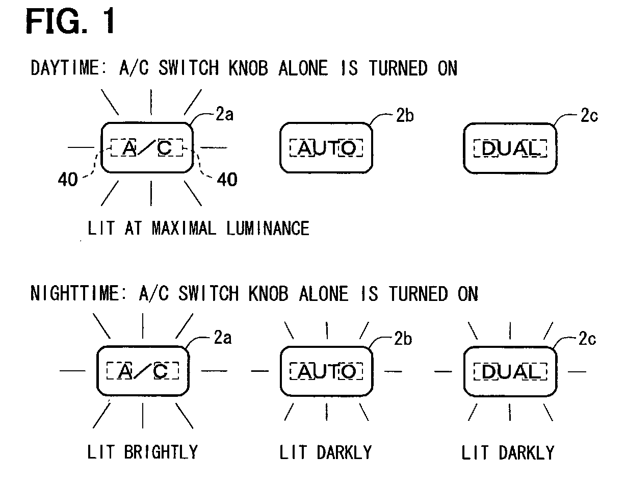
(57) An indicator drive system uses an indicator light source (40) on one line as an indicator
and a nighttime illuminator. When a low luminance adjustment is made, a small duty
cycle of a control signal can be avoided to reduce flicker and variation. Luminance
of indicator light sources (40) are controlled in descending order from daytime active
state, nighttime active state, nighttime illumination state, and daytime illumination
state. Light is adjusted by controlling the duty cycle of a control signal using a
first switching element (Tr1) connected on a main drive path (LM) and a second switching
element (Tr4) connected to a branch drive path (LB) on which a nighttime dimming current-limiting
load (D1-D3, R4) is connected. Since the current capacity of the branch drive path
(LB) is decreased due to the nighttime dimming current-limiting load (D1-D3, R4),
the duty cycle of the control signal for low luminance can be increased to suppress
flicker and variation in luminance.
|
|
