| (19) |
 |
|
(11) |
EP 1 635 110 B1 |
| (12) |
EUROPEAN PATENT SPECIFICATION |
| (45) |
Mention of the grant of the patent: |
|
29.09.2010 Bulletin 2010/39 |
| (22) |
Date of filing: 11.08.2005 |
|
| (51) |
International Patent Classification (IPC):
|
|
| (54) |
Disappearing facade element for illumination of building facades and facade including
said element
Zurückziehbares Fassadenelement zur Beleuchtung von Gebäudefassaden und Fassade, die
ein solches Element beinhaltet
Elément de façade rétractable pour l'illumination de façades de bâtiment et façade
comprenant un tel élément
|
| (84) |
Designated Contracting States: |
|
DE ES FR GB IT |
| (30) |
Priority: |
13.09.2004 IT MI20040422 U
|
| (43) |
Date of publication of application: |
|
15.03.2006 Bulletin 2006/11 |
| (73) |
Proprietor: Marazzi Group S.p.A. |
|
41100 Modena MO (IT) |
|
| (72) |
Inventor: |
|
- Marazzi, Filippo
41050 Colombaro MO (IT)
|
| (74) |
Representative: Faraggiana, Vittorio et al |
|
Ing. Barzanò & Zanardo Milano S.p.A.
Via Borgonuovo 10
20121 Milano
20121 Milano (IT) |
| (56) |
References cited: :
WO-A-02/052192
DE-A1- 19 624 707
US-A- 3 117 728
|
BE-A3- 1 013 381
DE-U1- 29 916 729
US-A- 5 682 131
|
|
| |
|
|
|
|
| |
|
| Note: Within nine months from the publication of the mention of the grant of the European
patent, any person may give notice to the European Patent Office of opposition to
the European patent
granted. Notice of opposition shall be filed in a written reasoned statement. It shall
not be deemed to
have been filed until the opposition fee has been paid. (Art. 99(1) European Patent
Convention).
|
[0001] This invention relates to a façade of a building provided with a disappearing lighting
element such that it does not interfere with the appearance of the façade in particular
during daytime.
[0002] The realization of façade lighting systems usable for example in nighttime hours
to produce plays of light and special aesthetic effects on the building is known in
the art.
[0003] Know lighting systems however generally include a plurality of floodlights fastened
on the outer façade of the building and remaining exposed even when not in use. These
lights, indeed, can ruin the aesthetic appearance of the façade and remain continuously
at the mercy of bad weather or possible vandalisms.
EP 0 921 253 A contains the preamble of claim 1.
[0004] BE 1013381 A3 discloses a movable panel containing a light source, which is housed in a niche in
a wall and can be rotated to project outside the wall surface to illuminate the wall
or the ceiling.
[0005] The general purpose of this invention is to remedy the above mentioned shortcomings
by making available a façade provided with a lighting system that does not interfere
with the overall aesthetic effect produced by the building and in particular in daylight
hours.
[0006] Another purpose of this invention is to make available a lighting system such that
the light source would remain exposed to bad weather or vandalism as little as possible.
[0007] In view of this purpose it was sought to provide in accordance with this invention
a building façade according to claim 1.
[0008] To clarify the explanation of the innovative principles of this invention and its
advantages compared with the prior art there is described below with the aid of the
annexed drawings a possible embodiment thereof by way of non-limiting example applying
said principles. In the drawings:
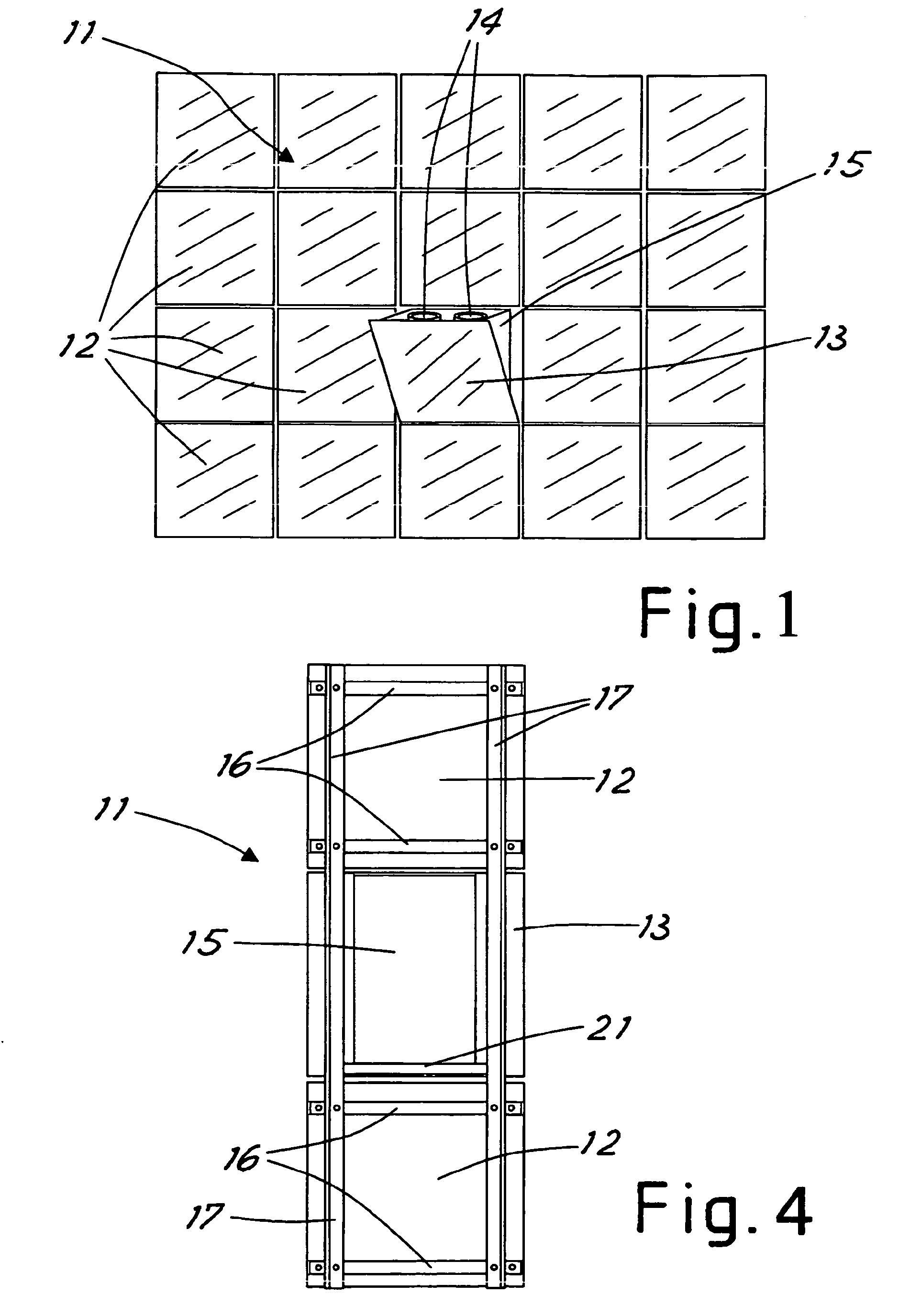
FIG 1 shows a view of a façade part having a lighting system in accordance with this
invention,
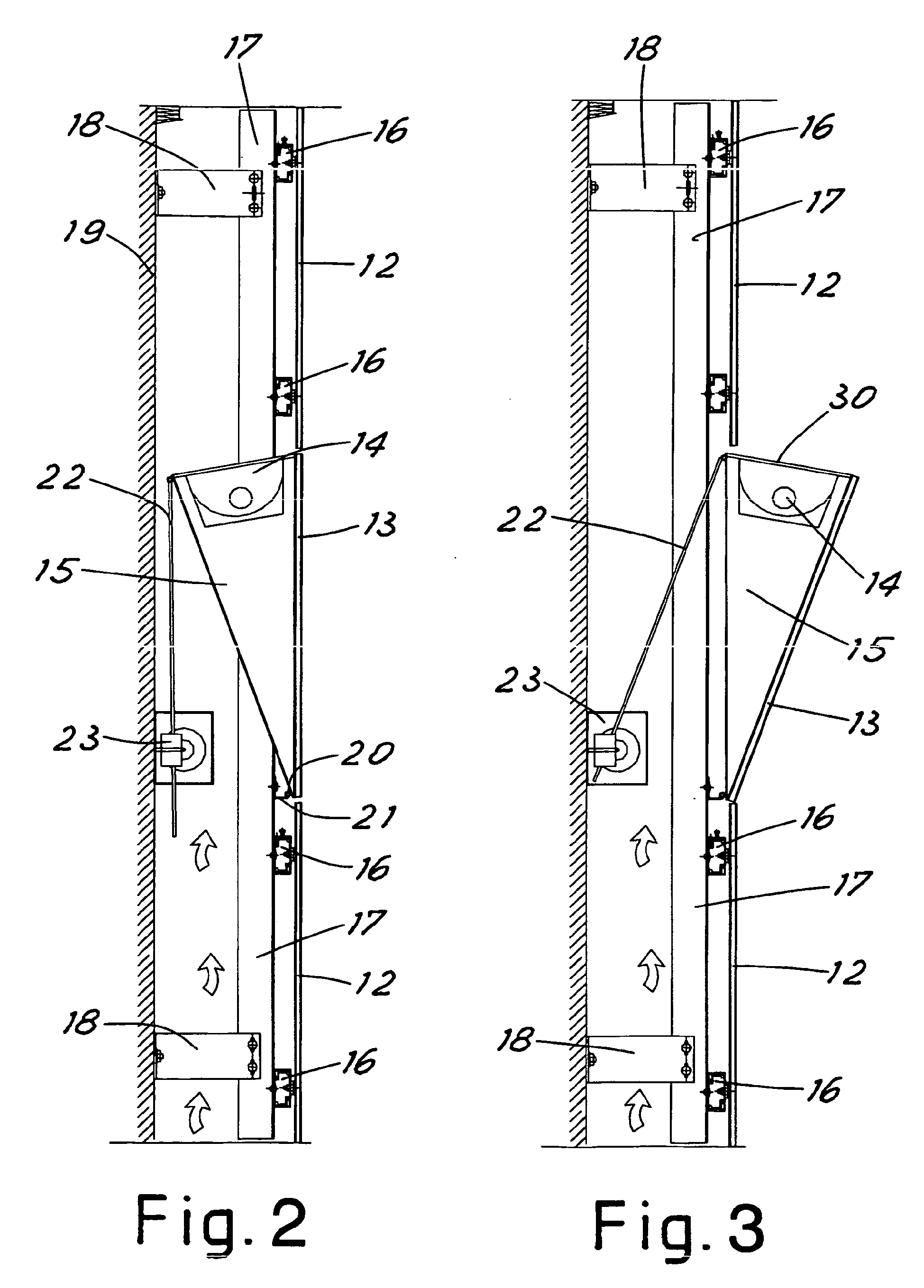
FIG 2 shows a side view of the lighting element of the façade with hidden light source,
FIG 3 shows another side view of the façade lighting element configured to illuminate
the building, and
FIG 4 shows a rear view of the lighting element inside the façade.
[0009] With reference to the figures, FIG 1 shows part of a façade 11 of a building including
a plurality of modular covering panels 12 for example rectangular tiles made of ceramic.
[0010] The panels 12 are virtually coplanar with each other and define the surface of the
façade 11. The panel 13, which can be sized identically to the panels 12, is movable
between a protruding position inclined to the façade surface (shown in FIG 1) and
a position coplanar with the façade plane.
[0011] When the panel 13 is in the protruding position, in the space between the panel and
the façade surface there is at least one light source 14 oriented with the light beam
toward the building façade. Two light sources realized in accordance with the prior
art are shown in the example of FIG 1.
[0012] In the protruding position the movable panel 13 could be inclined to the vertical
surface by an angle of between 5° and 30° which would be enough to allow the light
source to illuminate the building façade 11.
[0013] In one realization of this invention the light sources 14 are housed in a supporting
frame or structure 15 to which the movable panel 13 is fastened.
[0014] The supporting frame 15 together with the light source 14 and the movable panel 13
make up the façade element designed to supply the façade lighting.
[0015] FIG 2 shows a side view of the façade part where the façade element designed for
lighting is arranged and configured with the light source 14 hidden inside the façade.
[0016] In accordance with the prior art contrivances, each covering panel 12 is fastened
to a pair of horizontal support sections 16. The horizontal sections 16 are fastened
to vertical sections 17 which in turn are anchored to the wall 19 of the building
by appropriate clamps 18 also realized in accordance with prior art. Said contrivances
allow forming between the building panels and wall an air space which can be ventilated
if necessary in accordance with known techniques of the building industry.
[0017] The movable panel 13 differently from the panels 12 is fastened to a movable supporting
frame 15 forming a space designed to house the light source 14.
[0018] In one embodiment of this invention the frame 15 has a virtually prismatic form with
an acute triangular cross section. Opposite its narrow part, the frame 15 is hinged
to the support 21 through the horizontal hinge 20. The support 21 is fastened to the
above-mentioned vertical sections 17.
[0019] Opposite its wide part the frame 15 is constrained to the rod 22 for transport. The
rod 22 is moved by the powered driving gear 23 designed to shift the frame 15 between
the retracted position of FIG 2 and the protruding position of FIG 3.
[0020] The driving gear 23 is realized in accordance with the prior art and fastened to
the wall 19 of the building and controlled so as to move the movable panel 13 alternatively
between the position coplanar with the façade surface in daylight hours and the inclined
protruding position in the nighttime hours.
[0021] Advantageously the panel 13 is fastened to the frame 15 so as to rotate around its
lower horizontal edge.
[0022] It is noted that in FIG 3 the wide part of the space 15 is closed by a covering glass
30 designed to project the light source 14 when the panel 13 is in the protruding
position.
[0023] FIG 4 shows the three panels of FIG 2 from the inside of the façade with the handling
rod 22 and the driving gear 23 removed.
[0024] It is noted in particular that the two covering panels 12 are anchored to the horizontal
sections 16 which are in turn fastened to the vertical sections 17. The panel 13 on
the contrary is fastened to the supporting frame 15 which houses the light source
(not shown in the figures). The supporting frame 15 as mentioned above is hinged to
the support 21 and has a width less than that of the panels to be insertable between
the vertical sections 17 when the movable panel 13 is coplanar with the outer panels
12.
[0025] It is now clear that the preset purposes have been achieved. Indeed, when the movable
panel 13 is in the position coplanar with the façade surface the light source 14 is
positioned in the air space between the building wall and the façade without remaining
in view or exposed to vandalism.
[0026] When the movable panel 13 is in the protruding position of FIG 3 the façade is illuminated
while keeping the light source 14 little exposed behind the movable panel 13.
[0027] Naturally the above description of an embodiment applying the innovative principles
of this invention is given by way of non-limiting example of said principles within
the scope of the exclusive right claimed here.
[0028] In an unclaimed embodiment, the light source could be fastened inside the façade
as regards the building and there could be arranged on the movable panel a mirror
to reflect the source light towards the façade when the panel is in the protruding
position.
1. Building façade comprising a supporting structure (16, 17, 18) and a plurality of
modular, coplanar covering panels (12, 13) defining the surface of the façade and
supported by said supporting structure at a predetermined distance from a wall (19)
of the building to form an air space between the panels and the building wall, characterized in that at last one panel (13) of the plurality of panels contains a light source (14) for
illumination of the exterior of the façade and is movable between a position virtually
coplanar with the façade surface, in which the light source (14) is housed in said
air space, and a position protruding from the façade surface, in which the light source
(14) is operative to illuminate the exterior of the façade.
2. Building façade according to claim 1, characterized in that said at last one movable panel (13) has the same shape and size as the other nodular
panels (12) of the plurality of panels.
3. Building façade according to claim 1, characterized in that the light source (14) is integral with the movable panel (13).
4. Building façade according to claim 1, characterized in that the light source (14) is movable between a position inside the façade when the movable
panel (13) is coplanar with the façade surface and a position outside the façade surface
when the movable panel (13) is in the protruding position.
5. Building façade according to claim 1, characterized in that the movable panel (13) is fastened to a supporting frame (15) hinged to a support
integral with the building.
6. Building façade according to claim 5, characterized in that the hinging axis of the supporting frame (15) is horizontal.
7. Building façade according to claim 5, characterized in that the supporting frame (15) is movable by a powered driving gear device (23).
8. Building façade according to claim 5, characterized in that the light source (14) is fastened to the supporting frame (15) of the movable panel
(13).
9. Building façade according to claim 8, characterized in that the supporting frame (15) formes a space in which the light source (14) is housed,
with said space being closed by a light-source protection glass (30).
10. Building façade according to claim 1, characterized in that the movable panel (13) is rectangular.
11. Building façade according to claim 10, characterized in that the movable panel (13) is constrained to the façade in such a manner as to be rotatable
around one of its edges.
12. Building façade according to claim 11, characterized in that in the protruding position relative to the façade surface the movable panel (13)
is inclined at an angle between 5° and 30º to said façade surface.
13. Building façade according to claim 1, characterized in that the movable panel (13) is a ceramic tile.
1. Gebäudefassade, umfassend eine Tragkonstruktion (16, 17, 18) und eine Vielzahl von
modularen komplanaren Verkleidungsplatten (12, 13), welche die Oberfläche der Fassade
definieren und von der besagten Tragkonstruktion mit einem vorbestimmten Abstand zu
einer Wand (19) des Gebäudes getragen werden, um einen Luftzwischenraum zwischen den
Platten und der Gebäudewand zu bilden, dadurch gekennzeichnet, dass mindestens eine Platte (13) der Vielzahl von Platten eine Lichtquelle (14) zum Beleuchten
der Außenseite der Fassade enthält und zwischen einer praktisch zur Fassadenoberfläche
komplanaren Stellung, in der die Lichtquelle (14) im besagten Luftzwischenraum untergebracht
ist, und einer von der Fassadenoberfläche abstehenden Stellung bewegt werden kann,
in der die Lichtquelle (14) betriebsfähig ist, um die Außenseite der Fassade zu beleuchten.
2. Gebäudefassade nach Anspruch 1, dadurch gekennzeichnet, dass die mindestens eine bewegliche Platte (13) die gleiche Form und Größe wie die anderen
modularen Platten (12) der Vielzahl von Platten hat.
3. Gebäudefassade nach Anspruch 1, dadurch gekennzeichnet, dass die Lichtquelle (14) fest in die bewegliche Platte (13) eingebaut ist.
4. Gebäudefassade nach Anspruch 1, dadurch gekennzeichnet, dass die Lichtquelle (14) zwischen einer Position innerhalb der Fassade, wenn die bewegliche
Platte (13) komplanar zur Fassadenoberfläche ist, und einer Position außerhalb der
Fassadenoberfläche, wenn sich die bewegliche Platte (13) in der abstehenden Stellung
befindet, bewegt werden kann.
5. Gebäudefassade nach Anspruch 1, dadurch gekennzeichnet, dass die bewegliche Platte (13) an einem Tragrahmen (15) befestigt ist, der an einen gebäudefesten
Träger angelenkt ist.
6. Gebäudefassade nach Anspruch 5, dadurch gekennzeichnet, dass die Gelenkachse des Tragrahmens (15) horizontal ist.
7. Gebäudefassade nach Anspruch 5, dadurch gekennzeichnet, dass der Tragrahmen (15) durch eine motorisch angetriebene Antriebsgetriebevorrichtung
(23) bewegt werden kann.
8. Gebäudefassade nach Anspruch 5, dadurch gekennzeichnet, dass die Lichtquelle (14) am Tragrahmen (15) der beweglichen Platte (13) befestigt ist.
9. Gebäudefassade nach Anspruch 8, dadurch gekennzeichnet, dass der Tragrahmen (15) einen freien Raum bildet, in dem die Lichtquelle (14) untergebracht
ist, wobei dieser freie Raum mit einem Lichtquellen-Schutzglas (30) verschlossen ist.
10. Gebäudefassade nach Anspruch 1, dadurch gekennzeichnet, dass die bewegliche Platte (13) rechteckig ist.
11. Gebäudefassade nach Anspruch 10, dadurch gekennzeichnet, dass die bewegliche Platte (13) derart einseitig in die Fassade eingespannt ist, dass
sie um eine ihrer Kanten gedreht werden kann.
12. Gebäudefassade nach Anspruch 11, dadurch gekennzeichnet, dass die bewegliche Platte (13) in der im Verhältnis zur Fassadenoberfläche abstehenden
Stellung in einem Winkel zwischen 5° und 30° zu dieser Fassadenoberfläche geneigt
ist.
13. Gebäudefassade nach Anspruch 1, dadurch gekennzeichnet, dass die bewegliche Platte (13) eine Keramikplatte ist.
1. Façade de bâtiment comprenant une structure de support (16, 17, 18) et une pluralité
de panneaux de couvertures coplanaires modulaires (12, 13) définissant la surface
de la façade et supportés par ladite structure de support à une distance prédéterminée
d'une paroi (19) du bâtiment pour former un espace d'air entre les panneaux et la
paroi du bâtiment, caractérisée en ce qu'au moins un panneau (13) de la pluralité de panneaux contient une source lumineuse
(14) pour l'éclairage à l'extérieur de la façade et est mobile entre une position
virtuellement coplanaire avec la surface de façade, dans laquelle la source lumineuse
(14) est logée dans l'espace d'air, et une position faisant saillie de la surface
de façade, dans laquelle la source lumineuse (14) est fonctionnelle pour éclairer
l'extérieur de la façade.
2. Façade de bâtiment selon la revendication 1, caractérisée en ce que ledit au moins un panneau mobile (13) a les mêmes formes et dimensions que les autres
panneaux modulaires (12) de la pluralité de panneaux.
3. Façade de bâtiment selon la revendication 1, caractérisée en ce que la source lumineuse (14) est d'une seule pièce avec le panneau mobile (13).
4. Façade de bâtiment selon la revendication 1, caractérisée en ce que la source lumineuse (14) est mobile entre une position à l'intérieur de la façade
quand le panneau mobile (13) est coplanaire avec la surface de façade et une position
à l'extérieur de la surface de façade quand le panneau mobile (13) est dans la position
en saillie.
5. Façade de bâtiment selon la revendication 1, caractérisée en ce que le panneau mobile (13) est fixé à un cadre de support (15) articulé à un support
d'une seule pièce avec le bâtiment.
6. Façade de bâtiment selon la revendication 5, caractérisée en ce que l'axe d'articulation du cadre de support (15) est horizontal.
7. Façade de bâtiment selon la revendication 5, caractérisée en ce que le cadre de support (15) est déplaçable par un dispositif à pignon menant motorisé
(23).
8. Façade de bâtiment selon la revendication 5, caractérisée en ce que la source lumineuse (14) est fixé au cadre de support (15) du panneau mobile (13).
9. Façade de bâtiment selon la revendication 8, caractérisée en ce que le cadre de support (15) forme un espace dans lequel la source lumineuse (14) est
logée, avec ledit espace qui est fermé par un verre de protection de source lumineuse
(30).
10. Façade de bâtiment selon la revendication 1, caractérisée en ce que le panneau mobile (13) est rectangulaire.
11. Façade de bâtiment selon la revendication 10, caractérisée en ce que le panneau mobile (13) est lié à la façade de manière à pouvoir pivoter autour d'un
de ses bords.
12. Façade de bâtiment selon la revendication 11, caractérisée en ce que, dans la position en saillie par rapport à la surface de façade, le panneau mobile
(13) est incliné d'un angle entre 5° et 30° par rapport à ladite surface de façade.
13. Façade de bâtiment selon la revendication 1, caractérisée en ce que le panneau mobile (13) est un carreau céramique.
REFERENCES CITED IN THE DESCRIPTION
This list of references cited by the applicant is for the reader's convenience only.
It does not form part of the European patent document. Even though great care has
been taken in compiling the references, errors or omissions cannot be excluded and
the EPO disclaims all liability in this regard.
Patent documents cited in the description