(57) To enable efficient, and easy attachment of a shutoff operation cover at a proper
attaching position relative to two joining flange portions and also to restrict deformation
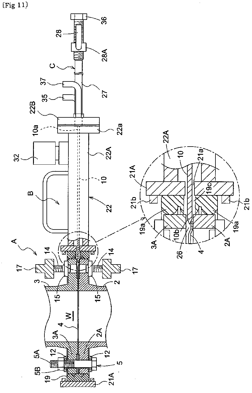
in a leading end portion of a gate plate valve. A shutoff operation cover B is attached
to two pipe portions 2, 3 jointed and fastened together with a fastener 5. The shutoff
operation cover B is capable of surrounding outer peripheries of the two joining flange
portions 2A, 3A under a sealed condition, and there is provided a gate plate valve
10 in the form of a thin plate, the valve being insertable and withdrawable for shutting
off conduits of the two pipe portions 2, 3. As the gate plate valve 10 is inserted
to a conduit shutting position through a gap S formed between the two joining flange
portions 2A, 3A in association with a loosening operation of the fastener 5, the conduit
is shut off between the two joining flange portions 2A, 3A. When the shutoff operation
cover B is attached to the two pipe portions 2, 3, a leading end 10b of the gate plate
valve 10 located at a conduit opening position is advanced into an annular gap 26
formed on the outer peripheral sides of opposing faces of the two joining flange portions
2A, 3A.
|
|
