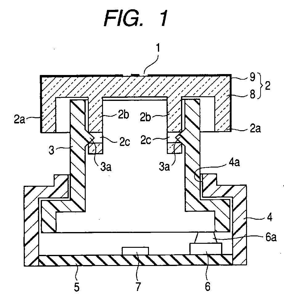
(57) Provided is an illumination switch device including: a manipulation knob (2) in which
a light shielding portion is provided in a front outer surface of a body formed of
a light transmitting material except for an illumination portion; hollow sliders (3),
each of which is incorporated into the manipulation knob (2) and is formed of a light
shielding material; a casing (4) which elevatably guides the slider (3); a switch
element (6) which is operated by the elevation movement of the slider (3) ; and a
light source (7) which irradiates light to a rear surface of the manipulation knob
(2) via an inner space of the slider (3), wherein a front end portion of the slider
(3) is disposed so as to protrude forward from the casing (4) and the manipulation
knob (2) is snap-connected to the front end portion of the slider (3) protruding from
the casing (4), wherein the manipulation knob (2) includes: a skirt portion (2a) which
protrudes backward from a peripheral edge portion of the body so as to surround the
front end portion of the slider (3); connection pieces (2b), each of which protrudes
backward from a rear surface of the body more than the skirt portion (2a) so as to
be inserted into the slider (3) ; and locking holes (2c), each of which is provided
in the connection piece (2b) so as to be located on the lower side of the skirt portion
(2a), and wherein an inner wall surface of the slider (3) is provided with a locking
claw which is snap-connected to the locking hole (2c).
|
|
