| (19) |
 |
|
(11) |
EP 1 873 873 B1 |
| (12) |
EUROPEAN PATENT SPECIFICATION |
| (45) |
Mention of the grant of the patent: |
|
11.04.2012 Bulletin 2012/15 |
| (22) |
Date of filing: 29.06.2007 |
|
| (51) |
International Patent Classification (IPC):
|
|
| (54) |
Fast-fit electric connecting device and use thereof for neutralizing a surplus high-voltage
output terminal of an electronic gas lighter for electric household appliances, in
particular a cooking range
Elektrische Anschlussvorrichtung mit schneller Montage und deren Verwendung zur Neutralisierung
einer überschüssigen Hochspannungsausgangsklemme eines elektronischen Gasanzünders
für elektrische Haushaltsgeräte, im Besonderen eines Küchenherdes
Dispositif de connexion électrique rapide et son utilisation pour neutraliser un excès
de terminal de sortie de haute tension d'un allumoir à gaz électronique pour appareils
électroménagers, en particulier une plaque de cuisson
|
| (84) |
Designated Contracting States: |
|
ES IT PL TR |
| (30) |
Priority: |
30.06.2006 IT TO20060484
|
| (43) |
Date of publication of application: |
|
02.01.2008 Bulletin 2008/01 |
| (73) |
Proprietor: ITW Industrial Components S.r.l.
con Unico Socio |
|
20122 Milano (IT) |
|
| (72) |
Inventors: |
|
- Pianezze, Daniele
21012, Cassano Magnago (IT)
- Saligari, Umberto
21040, Vedano Olona (IT)
|
| (74) |
Representative: Jorio, Paolo et al |
|
Studio Torta S.p.A.
Via Viotti, 9
10121 Torino
10121 Torino (IT) |
| (56) |
References cited: :
EP-A- 1 101 066
WO-A-00/07263
|
EP-A- 1 469 255
WO-A-84/03180
|
|
| |
|
|
|
|
| |
|
| Note: Within nine months from the publication of the mention of the grant of the European
patent, any person may give notice to the European Patent Office of opposition to
the European patent
granted. Notice of opposition shall be filed in a written reasoned statement. It shall
not be deemed to
have been filed until the opposition fee has been paid. (Art. 99(1) European Patent
Convention).
|
[0001] The present invention relates to a fast-fit electric connecting device intended to
be coupled to a terminal, in particular a high-voltage output terminal, of an electronic
gas lighter device for an electric household appliance; and to the use thereof for
neutralizing a surplus high-voltage output terminal exceeding the number of terminals
needed by the aforesaid gas lighter device by electrically grounding the surplus terminal,
in particular for electrically connecting the surplus terminal to an electric conducting
element of the electric household appliance, typically a cooking range, against which
the gas lighter device is intended to be integrally fastened in use, by means of screws
and/or by snap-fitting.
[0002] It is known that the lighting of gas fed cooking ranges for electric household appliances
is performed by means of electronic gas lighter devices, which are mounted in close
contact against the lower face of the cooking range, forming an electrically conducting
element normally electrically connected (e.g. by means of the terminal board of the
gas lighter device itself) to a reference potential (so-called "grounding connection"),
for safety reasons.
[0003] From
European patent n. 1101066B1 it is known to rapidly and electrically ground part of the lighting circuit of the
gas lighter device (in order to avoid electromagnetic interference) by means of a
U-shaped grounding spring which is integrally carried by the gas lighter device, astride
an edge of the electrically insulating casing of the gas lighter device itself, in
order to be sandwiched (squeezed) in use between such a casing and the electrically
conductive element of the cooking range, so that the circuit of the gas lighter device
is automatically grounded through the latter by means of the simple fixing of the
gas lighter device to the cooking range, generally obtained by snap-fitting, by means
of specific teeth of the casing which engage perforated seats of the cooking range,
and/or by means of screws.
[0004] Furthermore, from
European patent application n. EP 1469255A1 it is known that the gas lighter devices available on the market today all display
an even number of output terminals; each terminal is intended in use to supply high
voltage to a spark plug of a burner of a cooking range. Therefore, in the case of
a cooking range having an odd number of burners, a gas lighter device having an immediately
following even number of terminals must be used and the surplus terminal must be grounded,
by means of a specific wire, so as to neutralize the action thereof without damaging
the operation of the lighter.
[0005] A drawback of the above-described solution therefore consists in that the assembler
of the cooking range must use an additional grounding wire (as well as the grounding
wire prescribed by the specifications for the device as a whole, possibly replaced
by the U-spring according to
EP 1101066B1), with consequent increased costs, times and assembly difficulties (the operation
is normally performed in restricted spaces).
[0006] It is the object of the present invention to solve the drawbacks of the above-described
known devices of the prior art, by providing a fast-fit device for the electric connection
of a high-voltage output terminal of an electronic gas lighter device to an electric
conducting element of an electric household appliance, against which the gas lighter
device is intended to be integrally fixed in use, e.g. a cooking range, which is both
highly reliable, of low manufacturing and assembly cost and small in size, and which
essentially allows to completely avoid the use of grounding wires, without however
requiring modifications to the internal structure of the gas lighter device, such
as required instead by the solution to the same technical problem known from
EP 1469255A1.
[0007] The present invention thus relates to a device of the aforesaid type, as defined
in claim 1.
[0008] In particular, the device according to the invention is used, according to an aspect
of the invention, to neutralize, by means of grounding through the electric connection
to the mentioned electric conducting element of the electric household appliance,
of a high-voltage output terminal of the gas lighter device exceeding the number of
high-voltage output terminals needed by the electric household appliance itself.
[0009] The device according to the invention consists in an elastically deformable metallic
foil, comprising: a U-shaped assembly portion, adapted to be inserted in a contact
carrier stack of an electrically non-conducting casing of the gas lighter device;
and a working portion defined by an arm, which extends askew and cantilevered from
a first end of the assembly portion and which is shaped so as to be adapted, in use,
to extend in cantilevered manner out of the contact carrier stack and distanced from
the casing to cooperate in contact against the electrically conducting element.
[0010] The assembly portion is then provided with a slot for the mechanical and electrical
coupling with a respective blade contact (to be neutralized) accommodated within the
contact carrier stack of the casing of the gas lighter device and with a second end,
opposite to the first, and adapted to engage in use an internal side wall of the contact
carrier stack, consequent to an elastic deformation of the foil consequent to the
reciprocal contact between the cantilevered arm of the working portion and the electrically
conducting element of the electric household appliance.
[0011] In this manner, it is possible to arrange the contact device formed of the foil onto
the high-voltage terminal to be neutralized (e.g. the sixth terminal of a gas lighter
device intended to equip a cooking range having only five burners) simply by inserting
the assembly portion in the respective contact carrier stack corresponding to the
terminal to be neutralized, which is engaged in the slot of the foil, thus leaving
the arm askew and laterally cantilevered, transversally with respect to a longitudinal
axis of the gas lighter device, out of the stack and so as to be distanced in a cantilevered
manner from the casing of the gas lighter device, askew with respect to the aforesaid
axis of symmetry of the gas lighter device and towards the conducting element formed
by the cooking range.
[0012] Thus, as a consequence of the assembly of the gas lighter device on the cooking range,
performed for example by snapping or by means of screws as shown in
EP 1101066B1, the aforesaid arm extends askew and cantilevered from the stack of the terminal
to be neutralized with respect to the casing, and in direction so as to be distanced
from the casing itself, is pressed against the cooking range with at least its free
end by interference coupling, because it protrudes from the casing of the gas lighter
device towards the cooking range more than the clearance normally present in use,
after assembly, between casing of the gas lighter device and surface of the cooking
range of other conducting element of the electric household appliance to which the
gas lighter device is fixed in use (e.g. to the part of the armature of the household
appliance).
[0013] Therefore, the askew and cantilevered arm of the working portion of the connection
device according to the invention elastically bends, thus leading the coupling portion
of the stack to possibly turn (in the presence of sufficient clearance), on the terminal
to be neutralized (which serves as a hinge), taking the end of the assembly portion
opposite to the cantilevered arm and provided with specific teeth, to be driven into
the relatively soft synthetic plastic material, forming the side wall of the stack,
thus ensuring the impossibility of accidental removal of the foil of the fast-fit
connecting device according to the invention from the stack itself (and the relative
high-voltage terminal). In this manner, the surplus high-voltage terminal is actually
naturalized in permanent, simple and rapid manner, without the use of grounding wires
and without the need to internally modify the gas lighter device.
[0014] Further features and advantages of the present invention will be apparent from the
following description of a non-limitative embodiment thereof, with reference to the
accompanying drawings, in which:
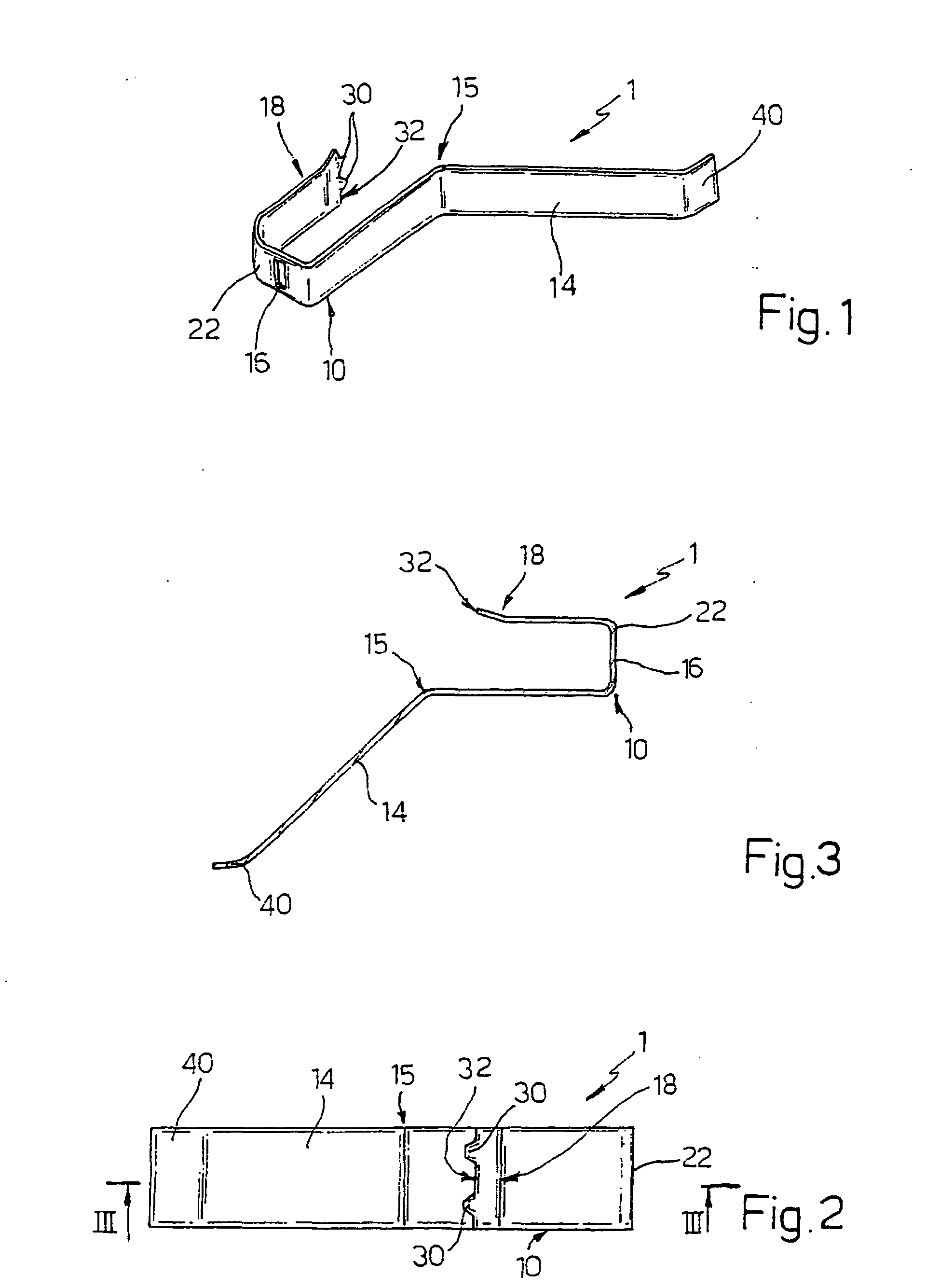
- figure 1 diagrammatically shows a perspective three-quarters top view of a fast-fit
electric connecting device made according to the invention;
- figure 2 shows an orthogonal plan view from the bottom of the device in figure 1;
- figure 3 shows a section view taken along a plotting plane III-III of the device in
figure 2; and
- figures 4 and 5 show a perspective view (figure 5 is a magnified detail) of an example
of use and assembly of the connection device in figures 1-3.
[0015] With reference to figures from 1 to 5, numeral 1 indicates as a whole a device for
the fast-fit electrical connection of a high-voltage output terminal 2 of an electronic
gas lighter device 3 (of known type, e.g. from
EP 1101066B1, and which is thus not further described in detail for the sake of simplicity) to
an electrically conducting element 4 of an electric household appliance (known and
not shown for the sake of simplicity) against which the gas lighter device 3 is intended
in use to be integrally fixed, e.g. to a lower surface of a cooking range equipped
with a certain number of burners, known and not shown, or a part of the carcass of
the electric household appliance.
[0016] Electrically conducting element 4 is normally connected (in known manner and not
shown for the sake of simplicity) to a reference potential, i.e. it is electrically
"grounded", e.g. by means of part of the electric circuit within device 3 itself and,
as shown below, device 1 is used according to the invention (figures 4 and 5) to neutralize
the ground connection (by means of element 4) of an output terminal 2b (figure 5)
exceeding the number of high-voltage output terminals 2 of gas lighter device 3 needed
by the household appliance, e.g. exceeding the number of burners of the cooking range
forming conducting element 4 (in general).
[0017] According to an aspect of the invention, electric connecting device 1 consists of
a simple elastically deformable metallic foil, particularly shaped by folding over
the elastic limit, so as to comprise a U-shaped assembly portion 10, adapted to be
inserted in use in a contact carrier stack 11 (figure 5) of an electrically non-conducting
casing 12 (e.g. formed by an injection moulded synthetic plastic material) of the
gas lighter device 3; and furthermore so as to comprise a working portion defined
by an arm 14, which extends askew and cantilevered from a first end 15 of assembly
portion 10 and which is shaped so as to be adapted, in use, to cooperate in contact
against electrically conducting element 4 (figure 4).
[0018] Assembly portion 10 is provided with a slot 16 for the mechanical and electrical
coupling with respective terminal 2b of the blade type accommodated within contact
carrier stack 11 of casing 12, and a second end 18, opposite to end 15, adapted to
engage in use to engage an internal side wall 21 of contact carrier stack 11, also
consequent to an elastic deformation of foil 1 consequent to the reciprocal contact
in use between cantilevered arm 14 and electrically conducting element 4 of the electric
household appliance.
[0019] Specifically, assembly portion 10 is asymmetrically U-shaped, where first end 15
forms a side branch having longer length than the asymmetric U and second end 18 forms
an opposite side branch, having a shorter length than the asymmetric U.
[0020] Furthermore, slot 16 is made through an intermediate connection segment 22 of the
U between the longer and the shorter length side branches formed by ends 15 and 18,
and is transversally oriented with respect to cantilevered arm 14 forming the working
portion, displaying (figure 1) a longitudinal direction of extension (length) oriented
perpendicularly with respect to a longitudinal direction of extension (length) of
cantilevered arm 14, identifiable in figure 2 with a perpendicular to the plane of
the sheet and with the plane of the sheet, respectively.
[0021] Finally, slot 16 displays dimensions such as to couple in use with a predetermined
clearance with blade terminal 2b to be neutralized of gas lighter device 3; such predetermined
clearance is specifically of an order such that elastically formable foil 1 may oscillate
in use on blade terminal 2b to which it is coupled within contact carrier stack 11
so as to press second end 18 against side wall 21 of stack 11; for the same purpose,
assembly portion 10 is also preferably shaped so as to be coupled with a slight predetermined
clearance within stack 11. In this manner, a very high assembly ease of device 1 on
gas lighter device 3 is obtained, also in the presence of relatively high machining
tolerances without, on the other hand, the risk of leading the electrical connection
of terminal 2b with element 4 through blade 1 to fail, as shown below.
[0022] Second end 18 is preferably provided with at least one anchoring tooth 30, even more
preferably with a pair of anchoring teeth 30 side by side, for anchoring side wall
21, essentially isosceles-triangle-shaped, adapted to be driven into side wall 21
of contact carrier stack 11 of casing 12 in virtue of the fact that the latter, as
the entire casing 12, are formed by relatively soft synthetic plastic material with
respect to the metallic material with which elastically deformable foil 1 forming
the fast-fit electric connection device of the invention is made, typically steel
(or other alloy, e.g. even brass) of the harmonic type.
[0023] Anchoring tooth 30 or pair of teeth 30 to wall 21 is/are cantilevered at an end edge
32 of second end 18 of assembly portion 10, which edge 32 (figure 3) was folded askew
(with respect to the branch of the U defined by end 18 itself) on opposite side to
the skew and cantilevered direction of extension of opposite arm 14 defined by end
15.
[0024] Cantilevered skew arm 14 is in turn provided with a free end 40 folded so as to be
essentially parallel to respective side branches of U-shaped assembly portion 10 when
metallic foil 1 is in undeformed conditions (figure 3).
[0025] As shown in figures 4 and 5, fast-fit electric connecting device 1 in figures 1-3
described herein is used in an innovative manner according to the invention to effectively
neutralize a high-voltage output terminal 2b of electronic gas lighter device 3 exceeding
the number of high-voltage output terminals 2 needed by the electric household appliance,
by grounding terminal 2b (surplus with respect to the total number of existing terminals
2) with electrically conducting element 4 of the electric household appliance, against
which gas lighter device 3 is however intended to be integrally fixed in use.
[0026] The use according to the invention is characterised in that elastically deformable
foil 1 is integrally mounted onto gas lighter device 3 with its assembly portion 10
inserted against contact carrier stack 11 of casing 12 corresponding to surplus terminal
2b and throughly accommodating the same; furthermore, slot 16 is, in such configuration,
mechanically and electrically connected to surplus terminal 2b, which is throughly
inserted across the same in assembly portion 10.
[0027] Concurrently, in the configuration described and illustrated in figures 4 and 5,
arm 14 is arranged askew and cantilevered from contact carrier stack 11 accommodating
terminal 2b and extends laterally cantilevered, transversally with respect to a longitudinal
axis A of gas lighter device 3 and out of stack 11, so as to be distanced in cantilevered
manner from casing 12 askew with respect to aforesaid axis A and towards conducting
element 4.
[0028] Finally, the use of the invention provides for the fixing in a known manner (besides
necessary in any case) of gas lighter device 3 to electrically conducting element
4, performed so that arm 14 is pressed, at least with its free end 40, against electrically
conducting element 4 with a force such as to press for example by elastic reaction
and/or by oscillation of foil 1 on terminal 2b and in stack 11, second end 18 of assembly
portion 10 (in particular edge 32 with teeth 30) against side wall 21 of stack 11.
1. A device (1) for the fast-fit electric connection of a high-voltage output terminal
(2) of an electronic gas lighter (3) to an electric conducting element (4) of an electric
household appliance upon which the gas lighter is intended in use to be integrally
fastened, for example a cooking range, in particular for neutralisation by grounding
connection of an output terminal (2b) exceeding the number of high-voltage output
terminals (2) of the gas lighter (3) needed by the electric household appliance; characterised in that it consists of an elastically deformable metallic foil (1) comprising: a U-shaped
assembly portion (10), adapted to be inserted in a contact carrier stack (11) of an
electrically non-conducting casing (12) of the gas lighter; and a working portion
defined by an arm (14), which extends askew and cantilevered from a first end (15)
of the assembly portion and which is shaped so as to be adapted, in use, to cooperate
in contact against the conducting element (4); the assembly portion (10) being provided
with a slot (16) for mechanical and electrical coupling with a respective blade terminal
(2) accommodated within said contact carrier stack of the gas lighter casing, and
a second end (18) opposite to the first and adapted to engage in use an internal side
wall (21) of the contact carrier stack, consequent to the reciprocal contact between
said cantilevered arm (14) of the working portion and the electrically conducting
element (4) of the electric household appliance.
2. A device according to claim 1, characterised in that said assembly portion (10) is asymmetrically U-shaped, said first end (15) forming
a side branch of a longer length of the asymmetric U and said second end (18) forming
an opposite side branch, of a shorter length of the asymmetric U.
3. A device according to claim 2, characterised in that said slot (16) for coupling with said blade contact of the gas lighter is made through
an intermediate connection segment (22) of the U between said longer side branch and
said shorter side branch.
4. A device according to any of the preceding claims, characterised in that said slot (16) for coupling with said blade contact of the gas lighter is transversally
oriented with respect to said cantilevered arm (14) of the working portion, presenting
a longitudinal direction of extension oriented perpendicularly with respect to a longitudinal
direction of extension of the cantilevered arm (14).
5. A device according to claim 4, characterised in that said slot (16) presents size so as to couple in use with predetermined clearance
with the blade contact (2b) of the gas lighter; said predetermined clearance being
such that said elastically deformable foil (1) may oscillate in use on the blade contact
(2b) which is coupled within said contact carrier stack so as to press said second
end (18) of said assembly portion against said side wall (21) of the stack, in particular
consequent to an elastic deformation of the foil (1).
6. A device according to one of the preceding claims, characterised in that said second end (18) of the assembly portion of said elastically deformable metallic
foil (1) is provided with at least one anchoring tooth (30), preferably with a pair
of anchoring teeth (30), to said side wall (21) of the contact carrier stack.
7. A device according to claim 6, characterised in that said at least one anchoring tooth (30) is adapted to be driven into said side wall
(21) of the contact carrier stack of the casing of the gas lighter; said casing (12)
being made of relatively soft synthetic plastic material relatively to the metallic
material with which said elastically deformable foil (1) is made.
8. A device according to claim 6 or 7, characterised in that said at least one anchoring tooth (30) is cantilevered at an end edge (32) of said
second end of the assembly portion folded askew on opposite side to the skew and cantilevered
direction of extension of said arm (14) of the working position of the elastic foil.
9. A device according to any of the preceding claims, characterised in that said cantilevered skew arm (14) is provided with a free end (40) folded so as to
be essentially parallel to respective side branches of the U-shaped assembly portion
(10) when the metallic foil is not deformed.
10. Use of a quick electric connection device (1) according to any of the preceding claims,
for neutralization of a high-voltage output terminal (2b) of an electronic gas lighter
(3) for an electric household appliance, exceeding the number of high-voltage terminals
(2) needed by the electric household appliance, by electric grounding connection of
the surplus terminal (2b) with an electric connecting element (4) of the electric
household appliance against which the gas lighter (3) is intended in use to be integrally
fastened; said use being characterised in that the elastically deformable foil (1) is integrally fitted to the gas lighter (3) with
its assembly portion (10) inserted in a contact carrier stack (11) of an electrically
non-conducting casing (12) of the gas lighter (3) accommodating the surplus terminal
(2b), mechanically and electrically connected to the surplus terminal (2b) by means
of said slot (16) in the assembly portion (10) and with said arm (14) in working position
askew protruding from the contact carrier stack (11); and by fastening said gas lighter
(3) to said electrically conducting element (4) so that said arm (14) is pressed at
least with one its free end (40) against the electric conducting element (4) with
such a force to press said second end (18) of the assembly portion (10) against a
side wall (21) of the contact carrier stack (11).
1. Vorrichtung (1) für die elektrische Verbindung mit schneller Montage eines Hochspannungs-Ausgangsanschlusses
(2) eines elektronischen Gasanzünders (3) mit einem elektrisch leitenden Element (4)
eines elektrischen Haushaltsgeräts, z. B. eines Kochherds, wobei vorgesehen ist, dass
der Gasanzünder in Gebrauch einteilig an ihm befestigt ist, insbesondere für die Neutralisation
durch eine Erdungsverbindung eines Ausgangsanschlusses (2b), der die Anzahl der Hochspannungsausgangsanschlüsse
(2) des Gasanzünders (3) übersteigt, die durch das elektrische Haushaltsgerät benötigt
werden; dadurch gekennzeichnet, dass sie aus einer elastisch verformbaren Metallfolie (1) besteht, die Folgendes umfasst:
einen U-förmigen Montageabschnitt (10), der beschaffen ist, um in einen Kontaktträgerstapel
(11) eines elektrisch nichtleitenden Gehäuses (12) des Gasanzünders eingesetzt zu
werden; und einen Arbeitsabschnitt, der durch einen Arm (14) definiert ist, der schief
und freitragend von einem ersten Ende (15) des Montageabschnitts verläuft und der
geformt ist, um in Gebrauch beschaffen zu sein, in Kontakt mit dem leitenden Element
(4) zusammenzuwirken; wobei der Montageabschnitt (10) mit einem Schlitz (16) für die
mechanische und elektrische Kopplung an einen entsprechenden Flachstecker (2), der
in dem Kontaktträgerstapel des Gasanzündergehäuses untergebracht ist, und einem zweiten
Ende (18), das dem ersten Ende gegenüberliegt und beschaffen ist, um in Gebrauch dem
wechselseitigen Kontakt zwischen dem freitragenden Arm (14) des Arbeitsabschnitts
und dem elektrisch leitenden Element (4) des elektrischen Haushaltsgeräts folgend
mit einer inneren Seitenwand (21) des Kontaktträgerstapels in Eingriff zu gelangen,
versehen ist.
2. Vorrichtung nach Anspruch 1, dadurch gekennzeichnet, dass der Montageabschnitt (10) asymmetrisch U-förmig ist, das erste Ende (15) einen Seitenzweig
mit einer größeren Länge des asymmetrischen U bildet und das zweite Ende (18) einen
gegenüberliegenden Seitenzweig mit einer kürzeren Länge des asymmetrischen U bildet.
3. Vorrichtung nach Anspruch 2, dadurch gekennzeichnet, dass der Schlitz (16) für die Kopplung mit dem Messerkontakt des Gasanzünders durch ein
Zwischenverbindungssegment (22) des U zwischen dem längeren Seitenzweig und dem kürzeren
Seitenzweig hergestellt ist.
4. Vorrichtung nach einem der vorhergehenden Ansprüche, dadurch gekennzeichnet, dass der Schlitz (16) für die Kopplung mit dem Messerkontakt des Gasanzünders bezüglich
des freitragenden Arms (14) des Arbeitsabschnitts transversal orientiert ist, was
eine Längsrichtung der Ausdehnung darstellt, die senkrecht bezüglich einer Längsrichtung
der Ausdehnung des freitragenden Arms (14) orientiert ist.
5. Vorrichtung nach Anspruch 4, dadurch gekennzeichnet, dass der Schlitz (16) eine Größe darstellt, um in Gebrauch mit einem vorgegebenen Zwischenraum
an den Messerkontakt (2b) des Gasanzünders gekoppelt zu sein; wobei der vorgegebene
Zwischenraum derart ist, dass die elastisch verformbare Folie (1) in Gebrauch an dem
Messerkontakt (2b) oszillieren kann, der in dem Kontaktträgerstapel gekoppelt ist,
um das zweite Ende (18) des Montageabschnitts gegen die Seitenwand (21) des Stapels
zu drücken, insbesondere einer elastischen Information der Folie (1) folgend.
6. Vorrichtung nach einem der vorhergehenden Ansprüche, dadurch gekennzeichnet, dass das zweite Ende (18) des Montageabschnitts der elastisch verformbaren Metallfolie
(1) mit wenigstens einem Verankerungszahn (30), vorzugsweise mit einem Paar Verankerungszähnen
(30) zu der Seitenwand (21) des Kontaktträgerstapels versehen ist,
7. Vorrichtung nach Anspruch 6, dadurch gekennzeichnet, dass der wenigstens eine Verankerungszahn (30) beschaffen ist, um in die Seitenwand (21)
des Kontaktträgerstapels des Gehäuses des Gasanzünders getrieben zu werden; wobei
das Gehäuse (12) aus einem relativ weichen synthetischen Kunststoffmaterial im Verhältnis
zu dem Metallmaterial hergestellt ist, aus dem die elastisch verformbare Folie (1)
hergestellt ist.
8. Vorrichtung nach Anspruch 6 oder 7, dadurch gekennzeichnet, dass der wenigstens eine Verankerungszahn (30) an einer Endkante (32) des zweiten Endes
des Zusammenbauabschnitts, der schief auf einer gegenüberliegenden Seite zu der schräg
verlaufenden und freitragenden Richtung der Ausdehnung des Arms (14) der Arbeitsposition
der elastischen Folie gefaltet ist, freitragend ist.
9. Vorrichtung nach einem der vorhergehenden Ansprüche, dadurch gekennzeichnet, dass der freitragende schräg verlaufende Arm (14) mit einem freien Ende (40) versehen
ist, das so gefaltet ist, um im Wesentlichen parallel zu den jeweiligen Seitenzweigen
des U-förmigen Montageabschnitts (10) zu sein, wenn die Metallfolie nicht verformt
ist.
10. Verwendung einer Vorrichtung (1) für die schnelle elektrische Verbindung nach einem
der vorhergehenden Ansprüche für die Neutralisation eines Hochspannungs-Ausgangsanschlusses
(2b) eines elektrischen Gasanzünders (3) für ein elektrisches Haushaltsgerät, der
die Anzahl der Hochspannungsanschlüsse (2), die durch das elektrische Haushaltsgerät
benötigt werden, übersteigt, durch die elektrische Erdungsverbindung des überschüssigen
Anschlusses (2b) mit einem elektrischen Verbindungselement (4) des elektrischen Haushaltsgeräts,
wobei vorgesehen ist, dass der Gasanzünder (3) in Gebrauch einteilig an ihm befestigt
ist; wobei die Verwendung dadurch gekennzeichnet ist, dass die elastisch verformbare Folie (1) einteilig an den Gasanzünder (3) montiert ist,
wobei ihr Montageabschnitt (10) in einen Kontaktträgerstapel (11) eines elektrisch
nichtleitenden Gehäuses (12) des Gasanzünders (3), das den überschüssigen Anschluss
(2b) aufnimmt, eingesetzt ist, mechanisch und elektrisch mit dem überschüssigen Anschluss
(2b) mittels des Schlitzes (16) in dem Montageabschnitt (10) verbunden ist und wobei
der Arm (14) in der Arbeitsposition von dem Kontaktträgerstapel (11) schief vorsteht;
und durch das Befestigen des Gasanzünders (3) an dem elektrisch leitenden Element
(4), so dass der Arm (14) wenigstens mit seinem einen freien Ende (40) gegen das elektrisch
leitende Element (4) mit einer derartigen Kraft gedrückt wird, um das zweite Ende
(18) des Montageabschnitts (10) gegen eine Seitenwand (21) des Kontaktträgerstapels
(11) zu drücken.
1. Dispositif (1) pour la connexion électrique rapide d'une borne de sortie haute tension
(2) d'un allumeur de gaz électronique (3) à un élément conducteur électrique (4) d'un
appareil domestique électrique sur lequel l'allumeur de gaz est destiné à être fixé
solidairement en service, par exemple une cuisinière, en particulier pour la neutralisation
par connexion de mise à la terre d'une borne de sortie (2b) dépassant le nombre de
bornes de sortie haute tension (2) de l'allumeur de gaz (3) dont l'appareil domestique
a besoin ; caractérisé en ce qu'il consiste en une feuille métallique élastiquement déformable (1) comprenant : une
partie d'assemblage en forme de U (10), adaptée pour être insérée dans un bloc porte-contact
(11) d'un boîtier électriquement non conducteur (12) de l'allumeur de gaz ; et une
partie de travail définie par un bras (14), qui s'étend en biais et en porte-à-faux
depuis une première extrémité (15) de la partie d'assemblage et qui est formé de manière
à être adapté, en service, de façon à coopérer en contact contre l'élément conducteur
(4) ; la partie d'assemblage (10) étant pourvue d'une fente (16) pour le couplage
mécanique et électrique avec une borne à couteau respective (2) logée à l'intérieur
dudit bloc porte-contact du boîtier de l'allumeur de gaz, et d'une deuxième extrémité
(18) en face de la première et adaptée de façon à s'engager en service avec une paroi
latérale interne (21) du bloc porte-contact, par suite du contact réciproque entre
ledit bras en porte-à-faux (14) de la partie de travail et l'élément électriquement
conducteur (4) de l'appareil domestique électrique.
2. Dispositif selon la revendication 1, caractérisé en ce que ladite partie d'assemblage (10) est formée en U asymétriquement, ladite première
extrémité (15) formant une branche latérale d'une longueur plus grande de l'U asymétrique
et ladite deuxième extrémité (18) formant une branche latérale opposée, d'une longueur
plus courte de l'U asymétrique.
3. Dispositif selon la revendication 2, caractérisé en ce que ladite fente (16) pour le couplage avec ledit contact à couteau de l'allumeur de
gaz est faite à travers un segment de connexion intermédiaire (22) de l'U entre ladite
branche latérale plus longue et ladite branche latérale plus courte.
4. Dispositif selon l'une quelconque des revendications précédentes, caractérisé en ce que ladite fente (16) pour le couplage avec ledit contact à couteau de l'allumeur de
gaz est orientée transversalement par rapport audit bras en porte-à-faux (14) de la
partie de travail, présentant une direction longitudinale d'extension orientée perpendiculairement
par rapport à une direction longitudinale d'extension du bras en porte-à-faux (14).
5. Dispositif selon la revendication 4, caractérisé en ce que ladite fente (16) présente une taille de manière à se coupler, en service, avec un
jeu prédéterminé avec le contact à couteau (2b) de l'allumeur de gaz ; ledit jeu prédéterminé
étant tel que ladite feuille déformable élastiquement (1) peut osciller en service
sur le contact à couteau (2b) qui est couplé à l'intérieur dudit bloc porte-contact
de façon à presser ladite deuxième extrémité (18) de ladite partie d'assemblage contre
ladite paroi latérale (21) du bloc, en particulier par suite d'une déformation élastique
de la feuille (1).
6. Dispositif selon l'une quelconque des revendications précédentes, caractérisé en ce que ladite deuxième extrémité (18) de la partie d'assemblage de ladite feuille métallique
déformable élastiquement (1) est pourvue d'au moins une dent d'ancrage (30), de préférence
d'une paire de dents d'ancrage (30), à ladite paroi latérale (21) du bloc porte-contact.
7. Dispositif selon la revendication 6, caractérisé en ce que ladite au moins une dent d'ancrage (30) est adaptée de façon à être enfoncée dans
ladite paroi latérale (21) du bloc porte-contact du boîtier de l'allumeur de gaz ;
ledit boîtier (12) étant fait en une matière plastique synthétique relativement molle
par rapport au matériau métallique avec lequel ladite feuille déformable élastiquement
(1) est faite.
8. Dispositif selon la revendication 6 ou 7, caractérisé en ce que ladite au moins une dent d'ancrage (30) est en porte-à-faux à un bord extrême (32)
de ladite deuxième extrémité de la partie d'assemblage pliée en biais sur le côté
opposé à la direction d'extension en biais et en porte-à-faux dudit bras (14) de la
position de travail de la feuille élastique.
9. Dispositif selon l'une quelconque des revendications précédentes, caractérisé en ce que ledit bras en biais en porte-à-faux (14) est pourvu d'une extrémité libre (40) pliée
de façon à être essentiellement parallèle aux branches latérales respectives de la
partie d'assemblage en forme de U (10) lorsque la feuille métallique n'est pas déformée.
10. Utilisation d'un dispositif de connexion électrique rapide selon l'une quelconque
des revendications précédentes, pour la neutralisation d'une borne de sortie haute
tension (2b) d'un allumeur de gaz électronique (3) pour un appareil domestique électrique,
dépassant le nombre de bornes haute tension (2) dont a besoin l'appareil domestique,
par la connexion de mise à la terre électrique de la borne en surplus (2b) avec un
élément de connexion électrique (4) de l'appareil domestique électrique contre lequel
l'allumeur de gaz (3) est destiné à être fixé solidairement en service ; ladite utilisation
étant caractérisée en ce que la feuille élastiquement déformable (1) est montée solidairement sur l'allumeur de
gaz (3) avec sa partie d'assemblage (10) insérée dans un bloc porte-contact (11) d'un
boîtier électriquement non conducteur (12) de l'allumeur de gaz (3) dans lequel se
trouve la borne en surplus (2b), raccordée mécaniquement et électriquement à la borne
en surplus (2b) au moyen de ladite fente (16) dans la partie d'assemblage (10) et
avec ledit bras (14) dans la position de travail en biais faisant saillie du bloc
porte-contact (11) ; et en fixant ledit allumeur de gaz (3) audit élément électriquement
conducteur (4) de manière à ce que ledit bras (14) soit pressé au moins avec une son
extrémité libre (40) contre l'élément conducteur électrique (4) avec une force telle
à presser la deuxième extrémité (18) de la partie d'assemblage (10) contre une paroi
latérale (21) du bloc porte-contact (11).

REFERENCES CITED IN THE DESCRIPTION
This list of references cited by the applicant is for the reader's convenience only.
It does not form part of the European patent document. Even though great care has
been taken in compiling the references, errors or omissions cannot be excluded and
the EPO disclaims all liability in this regard.
Patent documents cited in the description