| (19) |
 |
|
(11) |
EP 2 130 607 B1 |
| (12) |
EUROPEAN PATENT SPECIFICATION |
| (45) |
Mention of the grant of the patent: |
|
11.04.2012 Bulletin 2012/15 |
| (22) |
Date of filing: 06.06.2008 |
|
| (51) |
International Patent Classification (IPC):
|
|
| (54) |
Centrifugal separator
Zentrifugalabscheider
Séparateur par centrifugation
|
| (84) |
Designated Contracting States: |
|
AT BE BG CH CY CZ DE DK EE ES FI FR GB GR HR HU IE IS IT LI LT LU LV MC MT NL NO PL
PT RO SE SI SK TR |
| (43) |
Date of publication of application: |
|
09.12.2009 Bulletin 2009/50 |
| (73) |
Proprietor: Mantovani & Vicentini S.r.L. |
|
44033 Berra (FE) (IT) |
|
| (72) |
Inventor: |
|
- Vicentini, Leonardo
44033 Berra (Ferrara) (IT)
|
| (74) |
Representative: Alagem Modiano, Lara S. et al |
|
Dr. Modiano & Associati SpA
Via Meravigli 16
20123 Milano
20123 Milano (IT) |
| (56) |
References cited: :
EP-A- 0 423 461
US-A- 3 268 159
|
DE-A1- 1 482 721
US-A- 4 303 192
|
|
| |
|
|
|
|
| |
|
| Note: Within nine months from the publication of the mention of the grant of the European
patent, any person may give notice to the European Patent Office of opposition to
the European patent
granted. Notice of opposition shall be filed in a written reasoned statement. It shall
not be deemed to
have been filed until the opposition fee has been paid. (Art. 99(1) European Patent
Convention).
|
[0001] The present invention relates to a centrifugal separator for treating sludges, suspensions
and, in general, mixes of substances in the liquid phase and substances in the solid
phase, adapted to separate more or less accurately the liquid phase from the solid
phase.
[0002] Known types of centrifugal separator consists of a drum which rotates at high speed
and is provided with an internal screw feeder. The loaded sludge undergoes centrifugation,
during which the phases stratify; the phase with highest density (solid phase) is
arrange on the outermost annular region.
[0003] The screw feeder rotates at a different rate with respect to the drum and entrains
the solid phase toward the discharge. The water (liquid phase) exits from the opposite
side.
[0004] Known types of centrifugal separator have several drawbacks.
[0005] First of all, the liquid phase discharged by the separator is generally rather rich
in the solid sediments: this means that the separation process does not ensure the
result of correct separation of the solid phase from the liquid phase. When separation
is required by environmental needs (separation of pollutants) or by the need to recover
valuable material (treatment of mining sludges), it is absolutely necessary for the
separation to be as thorough as possible.
[0006] Secondly, it should be noted that continuous settling of solid material occurs along
the path of the discharge of the liquid phase and leads, in the medium and long term,
to obstruction of such path.
[0007] It is therefore necessary to provide continuous maintenance to clean the path: these
operations must provide for a rather complex machine architecture in order to ensure
easy access to the path to be cleaned. This constructive architecture necessarily
causes an increase in the production and design costs of the machine.
[0008] DE 14 82 721 A1 discloses a centrifugal separator having a combination of elements as set forth in
the pre-characterizing portion of the appended claim 1.
[0009] The aim of the present invention is to provide a centrifugal separator which is suitable
for high-performance separation of the solid phase and of the liquid phase of a mix.
[0010] Within this aim, an object of the present invention is to provide a centrifugal separator
in which settling of the solid phase along the liquid phase expulsion path does not
occur.
[0011] Another object of the present invention is to provide a centrifugal separator which
can be operated easily, since it does not require particular maintenance.
[0012] Another object of the present invention is to provide a centrifugal separator with
an architecture which is particularly simple and can be assembled easily.
[0013] Another object of the present invention is to provide a centrifugal separator which
has low costs, is relatively simple to provide in practice and is safe in application.
[0014] In accordance with the invention, there is provided a centrifugal separator as defined
in the appended claims.
[0015] Further characteristics and advantages of the invention will become better apparent
and evident from the following detailed description of a preferred but not exclusive
embodiment of a centrifugal separator, illustrated by way of non-limiting example
in the accompanying drawings, wherein.
Figure 1 is a sectional front view, taken along an axial longitudinal plane, of a
centrifugal separator according to the invention;
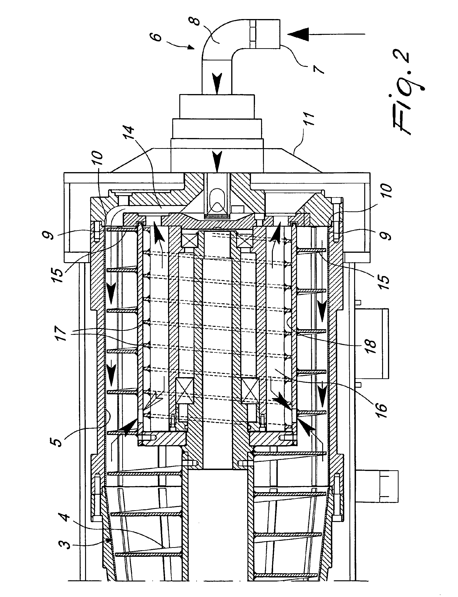
Figure 2 is an enlarged-scale sectional front view, taken along an axial longitudinal
plane, of a detail of a centrifugal separator according to the invention.
[0016] With reference to the figures, the reference numeral 1 generally designates a centrifugal
separator according to the invention.
[0017] A particularly simple and efficient embodiment is described hereafter: any structural
complication that entails the adoption of multiple equivalent components and/or the
partial use of the components that are present is to be understood as being comprised
in any case within the scope of the present description.
[0018] The centrifugal separator 1 comprises an outer casing 2, within which a hollow drum
3 is actuated so that it can rotate: with reference to the general nature of the description,
for example, the separator 1 might also comprise a plurality of mutually independent
drums 3 contained within a common casing 2 or within respective separate casings 2.
[0019] A first screw feeder 4 is actuated so that it can rotate, at a speed which is substantially
higher than the speed of the respective drum 3, inside the drum 3 itself; the first
screw feeder 4, during its relative rotation with respect to the corresponding drum
3, skins internal surfaces 5 thereof.
[0020] This relative motion is intended to convey the solids toward the outlet.
[0021] The same result can be achieved by working on the following parameters:
- direction of rotation
- turn winding direction
- relative speed of the screw feeder 4 and of the drum 3
[0022] The possible combinations for achieving correct operation (and therefore the desired
outflow of the solids) are the following:
➢ screw feeder 4 with right-handed helix, operating condition in which the drum 3
is faster than the screw feeder 4 with a clockwise rotation (if viewed from the liquid
discharge region);
➢ screw feeder 4 with right-handed helix, operating condition in which the drum 3
is slower than the screw feeder 4 with a counterclockwise rotation (if viewed from
the liquid discharge region);
➢ screw feeder 4 with left-handed helix, operating condition in which the drum 3 is
slower than the screw feeder 4 with a clockwise rotation (if viewed from the liquid
discharge region);
➢ screw feeder 4 with left-handed helix, operating condition in which the drum 3 is
faster than the screw feeder 4 with a counterclockwise rotation (if viewed from the
liquid discharge region).
[0023] Although only one of these constructive solutions is described in detail, it is evident
that they are equivalent from a mechanical standpoint and therefore are fully within
the scope of the protection of the present invention.
[0024] The separator 1 further comprises a circuit 6 for feeding a solid-liquid fit mix
and respective circuits for separate expulsion of the solid phase and of the liquid
phase.
[0025] The solid-liquid mix can be of different kinds: in particular, the separator 1 according
to the invention is suitable for treating sludge and the like, but use with other
mixes of another kind which require separation of the solid phase from the liquid
phase is not excluded.
[0026] It is noted that the separators 1 are particularly suitable for treating mixes for
purification purposes (therefore environmental use and the like) and for selection
purposes (use in mines or other plants adapted to provide a raw material which contains
a small part of valuable material to be selected).
[0027] In the centrifugal separator 1 according to the invention, the mix feed circuit 6
comprises an inlet 7 and a respective channel 8 which leads out along at least one
portion 9 of the internal surface 5 of the drum 3: this embodiment allows the delivery
of mix along the internal surface 5, proximate to its initial edge 10, of the rotating
drum 3.
[0028] This constructive choice to provide the separator 1 with the mix directly proximate
to the internal surface of the drum 3 allows to facilitate the immediate stratification
of the mix, with consequent centrifugal separation of the solid phase from the liquid
phase. In known types of separator, the mix is introduced coaxially with respect to
the drum and this entails a subsequent transfer by centrifugal action of such mix
toward the walls of the drum: of course, a transfer of the mix in this manner entails
the onset of turbulence which compromises the desired solid/liquid stratification.
[0029] Determining a constructive architecture in which the mix is dispensed directly in
the separator 1 proximate to the internal surface 5 of the drum 3 ensures that an
optimum centrifugal stratification is achieved immediately, minimizing interference
caused by any turbulence and the like.
[0030] In particular, the feed circuit 6 comprises one inlet 7 which is arranged at one
end 11 of the casing 2.
[0031] The end 11 is opposite to an end 12 in which an opening 13 for expelling the solid
phase is located.
[0032] The inlet 7 leads, by means of the respective channel 8, to an annular chamber 14,
which lies inside the casing 2 and the drum 3. The chamber 14 is adapted to force
the translational motion of the introduced mix in a radial direction by centrifugal
action toward the portion 9 of the internal wall 5 of the drum 3.
[0033] The annular input chamber 14 is arranged upstream of the beginning of a first start
15 of the first screw feeder 4.
[0034] The circuit for expelling the liquid phase comprises a channel 16, which is coaxial
to the at least one first screw feeder 4 and lies inside it in its portion located
further upstream. The channel 16 is adapted to convey the liquid phase with an axial
orientation with respect to the rotation axis of the separator 1 and in the opposite
direction with respect to the advancement direction of the solid phase on the drum
3 by way of the action of the first screw feeder 4.
[0035] In particular, the channel 16 comprises at least one portion of at least one second
screw feeder 17, in which the crests face, and are proximate to, an internal surface
18 of the channel 16 to remove any solid sediment from the surface 18 and to convey
the removed sediment toward the main screw feeder 4. Continuous removal of sediment
by the crests of the second screw feeder 17 from the internal surface 18 of the channel
16 ensures that such sediment does not accumulate and therefore that the operation
of the separator 1 is not compromised by the presence of solid sediment in the liquid
phase discharge channel 16. In practice, this solution entails the possibility to
reduce greatly maintenance interventions (aimed at cleaning the liquid phase discharge
channel) and therefore allows less expensive and simpler operation than known types
of separator.
[0036] It should be noted that the second screw feeder 17, in an embodiment of particular
interest in practice and in application, is constituted by a ribbonlike ring which
is arranged in a helical pattern on a plurality of radial supporting arms which extend
from the channel 16: this embodiment ensures that a channel 16 of large size is available
although the second screw feeder 17 designed to remove the sediment from the surface
18 is present.
[0037] The drum 3 and the first screw feeder 4 have a first upstream portion 19 which is
substantially cylindrical and a second downstream portion 20 which is substantially
frustum-shaped.
[0038] The first portion 19 is arranged directly downstream of the region where the mix
is introduced by the feed circuit 6, while the second portion 20 has its end part
substantially aligned with the opening 13 for expelling the solid phase.
[0039] The crest of the first screw feeder 4 faces, and is proximate to, the internal surface
5 of the drum 3, while the crest of the second screw feeder 17 faces, and is proximate
to, the internal surface 18 of the channel 16.
[0040] During operation, both crests skim the corresponding surfaces 5 and 18 to remove
and convey the solid phase deposited thereon.
[0041] The first screw feeder comprises, at a part 21 of the first portion 19, at least
one tubular portion 22, within which the second screw feeder 17 is accommodated so
that it can rotate.
[0042] The second screw feeder 17 is jointly connected to the corresponding drum 3; the
corresponding crests therefore slide proximate to the internal surface of the tubular
portion 22 of the first screw feeder 4: the starts of the second screw feeder 17 are
arranged in a helical winding direction which is opposite with respect to the direction
of the first screw feeder 4.
[0043] A relative speed of the first screw feeder 4 with respect to the drum 3 causes an
advancement, toward the respective expulsion opening 13, of the solid phase, in the
drum 3, by way of the action of the first screw feeder 4, and in the tubular portion
22, by way of the action of the second screw feeder 17. A positive relative speed
(which therefore corresponds to a higher rotation rate for the screw feeder 4 with
respect to the drum 3) in fact entails entrainment toward the opening 13 of the solid
matter comprised between the starts of the first screw feeder 4. Simultaneously, the
relative speed is such that the tubular portion 22 (connected to the first screw feeder
4) move at a higher speed than the second screw feeder 17 (the relative speed is therefore
negative in this case): since the helical winding direction is opposite with respect
to the one of the first screw feeder 4, transfer of the sediment that is present on
the surface of the channel 16 (internal surface of the portion 22) toward the opening
13 still occurs.
[0044] The separator 1 further comprises at least one external traction unit (not shown
in the figure), which is intended to drive rotationally the drum 3, jointly with the
second screw feeder 17, and the first screw feeder 4.
[0045] In particular, it is possible to adopt a single unit which is associated with respective
pulleys 23 and 24 having different diameters, one pulley 23 being coupled to the drum
3 and to the second screw feeder 17 and the other pulley 24 being coupled to the first
screw feeder 4.
[0046] The different diameter of the pulleys 23, 24 determines the different rotation rate
of the drum 3 with respect to the first screw feeder 4.
[0047] Introduction of the mix through the circuit 6 entails that such mix flows by way
of the action of the first screw feeder along the part 21 until it reaches the end
of the first upstream portion 19.
[0048] At the end of the portion 19 there are passages 25 designed to allow the outflow
of the liquid phase through the respective channel 16.
[0049] The remaining solid phase continues to be entrained by the first screw feeder 4 to
the opening 13: the centrifugal action contributes, throughout the entrainment, to
separate from the solid phase the liquid phase, which tends to retract to be then
expelled through the channel 16.
[0050] The second screw feeder 17 (by way of its relative movement with respect to the walls
of the channel constituted by the internal surface of the tubular portion 22 of the
screw feeder 4) removes sediment from the surfaces that face it.
[0051] It has thus been shown that the invention achieves the proposed aim and objects.
[0052] The invention thus conceived is susceptible of numerous modifications and variations,
all of which are within the scope of the appended claims.
[0053] Where technical features mentioned in any claim are followed by reference signs,
those reference signs have been included for the sole purpose of increasing the intelligibility
of the claims and accordingly such reference signs do not have any limiting effect
on the interpretation of each element identified by way of example by such reference
signs.
1. A centrifugal separator (1), of the type that comprises an outer casing (2), within
which at least one hollow drum (3) is actuated so that it can rotate, at least one
first screw feeder (4) which is actuated so that it can rotate, at a speed which is
substantially higher than the speed of the respective drum (3), within said drum (3),
skimming its internal surfaces (5), a circuit (6) for feeding a solid-liquid mix and
respective circuits for the separate expulsion of the solid phase and of the liquid
phase, the mix feed circuit (6) comprising an inlet (7) and a respective channel (8)
which leads out along at least one portion (9) of the internal surface (5) of said
drum (3) to dispense mix along the internal surface. (5) of said rotatable drum (3),
said circuit for expelling the liquid phase comprising a channel (16) which is coaxial
to said at least one first screw feeder (4) and is internal thereto in its portion
located further upstream, said channel (16) being adapted to convey said separated
liquid phase in an axial orientation with respect to the rotation axis of the separator
(1) and in the opposite direction with respect to the advancement direction of said
solid phase on the at least one drum (3) by way of the action of said at least one
first screw feeder (4), said channel (16) comprising at least one portion of at least
one second screw feeder (17) whose crests face, and lie proximate to, the internal
surface (18) of said channel (16) for the removal of any solid sediment from said
surface (18) and for the conveyance of said removed sediment towards the at least
one first main screw feeder (4), characterized in that said feed circuit (6) comprises an inlet (7) which is arranged at an end (11) of
said casing (2), said end (11) being arranged opposite the end (12) in which the opening
(13) for expelling the solid phase is arranged, said inlet (7) leading, by means of
a channel (8), to an annular chamber (14) which lies inside said casing (2) and said
at least one drum (3), said chamber (14) being adapted to impose a translational motion
in a radial direction by centrifugal action, toward at least one portion (9) of the
internal wall (5) of said at least one drum (3), of the introduced mix, said annular
intake chamber (14) being arranged upstream of the beginning of the first start (15)
of said at least one first screw feeder (4).
2. The centrifugal separator according to claim 1, characterized in that said at least one drum (3) and said corresponding at least one first screw feeder
(4) have a first upstream portion (19) which is substantially cylindrical and a second
downstream portion (20) which is substantially frustum-shaped, said first portion
(19) being arranged directly downstream of the region where the mix is introduced
by said feed circuit (6) and said second portion (20) having its end part which is
substantially aligned with an opening (13) for expelling the solid phase.
3. The centrifugal separator according to claim 1, characterized in that the crest of said at least one first screw feeder (4) and the crest of said at least
one second screw feeder (17) face, and lie proximate to, respectively the internal
surface (5) of said drum (3) and to the internal surface (18) of said channel (16),
skimming, during the operation of said separator (1), said surfaces (5) and (18) to
remove and convey the solid phase deposited thereon.
4. The centrifugal separator according to one or more of the preceding claims, characterized in that said at least one first screw feeder (4) comprises, at a part (21) of said first
portion (19), at least one tubular portion (22), within which the at least one second
screw feeder (17) is accommodated so that it can rotate.
5. The centrifugal separator according to one or more of the preceding claims, characterized in that said at least one second screw feeder (17) is coupled to the corresponding drum (3),
the corresponding crests sliding proximate to the internal surface (18) of said tubular
portion (22) of said first screw feeder (4), the starts of said at least one second
screw feeder (17) being arranged in the opposite direction with respect to the starts
(15) of said at least one first screw feeder (4), a relative speed of the first screw
feeder (4) with respect to the drum (3) producing an advancement, toward the respective
expulsion opening (13), of the solid phase in the drum (3) by way of the action of
the at least one first screw feeder (4) and in the tubular portion (22) by way of
the action of the at least one second screw feeder (17).
6. The centrifugal separator according to one or more of the preceding claims, characterized in that it comprises at least one external traction unit which is intended to entrain rotationally
said at least one hollow drum (3) jointly with the at least one second screw feeder
(17) and said at least one first screw feeder (4).
7. The centrifugal separator according to the preceding claim, characterized in that said unit is a single unit and is associated with respective pulleys (23, 24) having
different diameters, one pulley (23) being coupled to said at least one drum (3) and
to said second screw feeder (17) and the other pulley (24) being coupled to said first
screw feeder (4), the different diameter of the pulleys (23, 24) determining the different
rotation rate of the at least one drum (3) with respect to the at least one first
screw feeder (4).
1. Fliehkraftabscheider (1), von der Art, die ein äußeres Gehäuse (2), innerhalb dessen
wenigstens eine hohle Trommel (3) betrieben wird, so dass sie sich drehen kann, wenigstens
eine erste Dosierschnecke (4), die betrieben wird, so dass sie sich innerhalb der
Trommel (3) mit einer Geschwindigkeit drehen kann, die wesentlich größer ist als die
Geschwindigkeit der entsprechenden Trommel (3), wobei sie deren innere Oberfläche
(5) abzieht, eine Leitung (6) zum Zuführen eines Fest-Flüssig-Gemisches und entsprechende
Leitungen zum separaten Abführen der festen Phase und der flüssigen Phase umfasst,
wobei die Gemischzuführleitung (6) einen Einlass (7) und einen entsprechenden Kanal
(8) umfasst, der entlang wenigstens eines Anteils (9) der inneren Oberfläche (5) der
Trommel (3) verläuft, um Gemisch entlang der inneren Oberfläche (5) der drehbaren
Trommel (3) abzugeben, wobei die Leitung zum Abführen der flüssigen Phase einen Kanal
(16) umfasst, der koaxial und mit seinem Anteil, der stromaufwärts angeordnet ist,
innerhalb mit der wenigstens einen ersten Dosierschnecke (4) verläuft, wobei der Kanal
(16) angepasst ist, um durch die Wirkung der wenigstens einen Dosierschnecke (4) die
abgetrennte flüssige Phase in einer axialen Orientierung bezüglich der Drehachse des
Abscheiders (1) und in die entgegengesetzte Richtung relativ zu der Förderrichtung
der festen Phase in der wenigstens einen Trommel (3) zu förderen, wobei der Kanal
(16) wenigstens einen Anteil wenigstens einer zweiten Dosierschnecke (17) aufweist,
deren Kronen zu der inneren Oberfläche (18) des Kanals (16) weisen und an dieser unmittelbar
anliegen, um jegliches feste Sediment von dieser Oberfläche (18) zu entfernen und
in Richtung auf die wenigstens eine erste Hauptdosierschnecke (4) zu fördern, dadurch gekennzeichnet, dass die Zuführleitung (6) einen Einlass (7) aufweist, der an einem Ende (11) des Gehäuses
(2) angeordnet ist, wobei das Ende (11) dem Ende (12) gegenüber angeordnet ist, in
dem die Öffnung (13) zum Abführen der festen Phase angeordnet ist, wobei der Einlass
(7) mittels eines Kanals (8) zu einer ringförmigen Kammer (14) führt, die im Inneren
des Gehäuses (2) und der wenigstens einen Trommel (3) liegt, wobei die Kammer (14)
angepasst ist, bei dem eingeführten Gemisch eine translatorische Bewegung in radialer
Richtung durch die Zentrifugalkraft in Richtung auf wenigstens einen Anteil (9) der
inneren Wand (5) der wenigstens einen Trommel (3) hervorzurufen, wobei die ringförmige
Aufnahmekammer (14) stromaufwärts des Beginns des ersten Gewindeganges (15) der wenigstens
einen ersten Dosierschnecke (4) angeordnet ist.
2. Fliehkraftabscheider nach Anspruch 1, dadurch gekennzeichnet, dass die wenigstens eine erste Trommel (3) und die wenigstens eine erste entsprechende
Dosierschnecke (4) einen ersten Stromaufwärtsanteil (19), der im Wesentlichen zylindrisch
ist, und einen zweiten Stromabwärtsanteil (20), der im Wesentlichen kegelstumpfförmig
ist, aufweisen, wobei der erste Anteil (19) unmittelbar stromabwärts der Region angeordnet
ist, wo das Gemisch durch die Zuführleitung (6) eingebracht wird, und wobei der zweite
Anteil (20) einen Endanteil aufweist, der im Wesentlichen mit einer Öffnung (13) zum
Abführen der festen Phase ausgerichtet ist.
3. Fliehkraftabscheider nach Anspruch 1, dadurch gekennzeichnet, dass die Krone der wenigstens einen ersten Dosierschnecke (4) und die Krone der wenigstens
einen zweiten Dosierschnecke (17) zu der inneren Oberfläche (5) der Trommel (3) beziehungsweise
zu der inneren Oberfläche (18) des Kanals (16) weisen und an dieser unmittelbar anliegen
und während des Betriebs des Abscheiders (1) diese Oberflächen (5) und (18) abziehen,
um die feste Phase, die sich daran abgelagert hat, zu entfernen und zu transportieren.
4. Fliehkraftabscheider nach einem oder mehreren der vorstehenden Ansprüche, dadurch gekennzeichnet, dass die wenigstens eine erste Dosierschnecke (4) an einem Teil (21) des ersten Anteils
(19) wenigstens einen rohrförmigen Anteil (22) umfasst, innerhalb dessen die wenigstens
eine zweite Dosierschnecke (17) so gelagert ist, dass sie sich drehen kann.
5. Fliehkraftabscheider nach einem oder mehreren der vorstehenden Ansprüche, dadurch gekennzeichnet, dass die wenigstens eine zweite Dosierschnecke (17) mit der entsprechenden Trommel (3)
gekoppelt ist, wobei die entsprechenden Kronen an der inneren Oberfläche (18) des
rohrförmigen Anteils (22) der ersten Dosierschnecke (4) entlang gleiten, wobei die
Gewindegänge der wenigstens einen zweiten Dosierschnecke (17) in entgegengesetzter
Richtung bezüglich der Gewindegänge (15) der wenigstens einen ersten Dosierschnecke
(4) angeordnet sind, wobei eine relative Geschwindigkeit der ersten Dosierschnecke
(4) bezüglich der Trommel (3) eine Förderung in Richtung auf die entsprechende Abführöffnung
(13) für die feste Phase in der Trommel (3) durch die Wirkung der wenigstens einen
ersten Dosierschnecke (4) und in dem rohrförmigen Anteil (22) durch die Wirkung der
wenigstens einen zweiten Dosierschnecke (17) hervorruft.
6. Fliehkraftabscheider nach einem oder mehreren der vorstehenden Ansprüche, dadurch gekennzeichnet, dass er wenigstens eine externe Zugeinheit umfasst, die vorgesehen ist, um die wenigstens
eine hohle Trommel (3) gemeinsam mit der wenigstens einen zweiten Dosierschnecke (17)
und der wenigstens einen ersten Dosierschnecke (4) zu drehen.
7. Fliehkraftabscheider nach dem vorstehenden Anspruch, dadurch gekennzeichnet, dass die Einheit eine einzelne Einheit ist und mit entsprechenden Scheiben (23, 24) verbunden
ist, die unterschiedliche Durchmesser aufweisen, wobei eine Scheibe (23) mit der wenigstens
einen Trommel (3) und der zweiten Dosierschnecke (17) verbunden ist und die andere
Scheibe (24) mit der ersten Dosierschnecke (4) verbunden ist, und wobei die unterschiedlichen
Durchmesser der Scheiben (23, 24) die unterschiedliche Drehrate der wenigstens einen
Trommel (3) relativ zu der wenigstens einen ersten Dosierschnecke (4) bestimmen.
1. Séparateur centrifuge (1), du type comportant un carter extérieur (2), à l'intérieur
duquel au moins un tambour creux (3) est actionné de manière à pouvoir tourner, au
moins une première vis de distribution (4) actionnée de manière à pouvoir tourner,
à une vitesse sensiblement plus élevée que la vitesse du tambour respectif (3), à
l'intérieur dudit tambour (3), frôlant ses surfaces intérieures (5), un circuit (6)
d'alimentation en mélange solide-liquide et des circuits respectifs pour l'expulsion
séparée de la phase solide et de la phase liquide, le circuit d'alimentation (6) comprenant
une entrée (7) et un canal respectif (8) qui débouche le long d'au moins une partie
(9) de la surface intérieure (5) dudit tambour (3) pour distribuer le mélange le long
de la surface intérieure (5) dudit tambour rotatif (3), ledit circuit pour expulser
la phase liquide comprenant un canal (16) qui est coaxial à ladite au moins une première
vis de distribution (4) et est à l'intérieur de celle-ci dans sa partie située plus
en amont, ledit canal (16) permettant d'acheminer ladite phase liquide séparée suivant
une orientation axiale par rapport à l'axe de rotation du séparateur (1) et dans la
direction opposée par rapport à la direction de progression de ladite phase solide
sur le/les tambours (3) sous l'action de ladite au moins une première vis de distribution
(4), ledit canal (16) comprenant au moins une partie d'au moins une seconde vis de
distribution (17) dont les crêtes sont en regard, et se trouvent tout près, de la
surface intérieure (18) dudit canal (16) pour détacher d'éventuels dépôts solides
de ladite surface (18) et pour acheminer lesdits dépôts détachés vers la/les premières
vis de distribution (4), caractérisé en ce que ledit circuit d'alimentation (6) comprend une entrée (7) ménagée à une extrémité
(11) dudit carter (2), ladite extrémité (11) étant ménagée à l'opposé de l'extrémité
(12) dans laquelle est ménagée l'ouverture (13) pour l'expulsion de la phase solide,
ladite extrémité (7) débouchant, par un canal (8), dans une chambre annulaire (14)
qui se trouve à l'intérieur dudit carter (2) et dudit/desdits tambours (3), ladite
chambre (14) permettant d'imposer par action centrifuge un mouvement de translation
dans une direction radiale, vers au moins une partie (9) de la paroi intérieure (5)
dudit/desdits tambours (3), du mélange introduit, ladite chambre annulaire d'admission
(14) étant ménagée en amont du début du premier filet (15) de ladite au moins une
vis de distribution (4).
2. Séparateur centrifuge selon la revendication 1, caractérisé en ce que ledit au moins un tambour (3) et ladite au moins une première vis de distribution
correspondante (4) ont une première partie amont (19) sensiblement cylindrique et
une seconde partie aval (20) de forme sensiblement tronconique, ladite première partie
(19) étant disposée juste en aval de la zone où le mélange est introduit par ledit
circuit d'alimentation (6) et ladite seconde partie (20) ayant sa partie terminale
sensiblement alignée avec une ouverture (13) pour l'expulsion de la phase solide.
3. Séparateur centrifuge selon la revendication 1, caractérisé en ce que la crête de ladite au moins une première vis de distribution (4) et la crête de ladite
au moins une seconde vis de distribution (17) sont en regard, et se trouvent tout
près, respectivement, de la surface intérieure (5) dudit tambour (3) et de la surface
intérieure (18) dudit canal (16), frôlant, pendant la marche dudit séparateur (1),
lesdites surfaces (5) et (18) afin de détacher et d'acheminer la phase solide déposée
sur celles-ci.
4. Séparateur centrifuge selon une ou plusieurs des revendications précédentes, caractérisé en ce que ladite au moins une vis de distribution (4) comprend, à un endroit (21) de ladite
première partie (19), au moins une partie tubulaire (22) dans laquelle la/les secondes
vis de distribution (17) est/sont logées de manière à pouvoir tourner.
5. Séparateur centrifuge selon une ou plusieurs des revendications précédentes, caractérisé en ce que ladite au moins une seconde vis de distribution (17) est montée dans le tambour correspondant
(3), les crêtes correspondantes glissant tout près de la surface intérieure (18) de
ladite partie tubulaire (22) de ladite première vis de distribution (4), les filets
de ladite au moins une seconde vis de distribution (17) étant disposés en sens inverse
par rapport aux filets (15) de ladite au moins une première vis de distribution (4),
une vitesse relative de la première vis de distribution (4) par rapport au tambour
(3) produisant une progression, vers l'ouverture d'expulsion respective (13), de la
phase solide dans le tambour (3) sous l'action de la/des premières vis de distribution
(4) et dans la partie tubulaire (22) sous l'action de la/des secondes vis de distribution
(17).
6. Séparateur centrifuge selon une ou plusieurs des revendications précédentes, caractérisé en ce qu'il comporte au moins un système extérieur de traction destiné à entraîner en rotation
ledit au moins un tambour creux (3) conjointement avec ladite/lesdites secondes vis
de distribution (17) et ladite/lesdites première vis de distribution (4).
7. Séparateur centrifuge selon la revendication précédente, caractérisé en ce que ledit système est un système unique et est associé à des poulies respectives (23,
24) de diamètre différent, une première poulie (23) étant accouplée avec ledit au
moins un tambour (3) et avec ladite seconde vis de distribution (17) et l'autre poulie
(24) étant accouplée avec ladite première vis de distribution (4), le diamètre différent
des poulies (23, 24) déterminant la vitesse de rotation différente du/des tambours
(3) par rapport à celle de la/des premières vis de distribution (4).

REFERENCES CITED IN THE DESCRIPTION
This list of references cited by the applicant is for the reader's convenience only.
It does not form part of the European patent document. Even though great care has
been taken in compiling the references, errors or omissions cannot be excluded and
the EPO disclaims all liability in this regard.
Patent documents cited in the description