| (19) |
 |
|
(11) |
EP 2 021 224 B1 |
| (12) |
EUROPEAN PATENT SPECIFICATION |
| (45) |
Mention of the grant of the patent: |
|
03.10.2012 Bulletin 2012/40 |
| (22) |
Date of filing: 30.05.2007 |
|
| (51) |
International Patent Classification (IPC):
|
| (86) |
International application number: |
|
PCT/IB2007/001419 |
| (87) |
International publication number: |
|
WO 2007/138458 (06.12.2007 Gazette 2007/49) |
|
| (54) |
CAR STEERING SYSTEM
AUTOLENKSYSTEM
SYSTÈME DE DIRECTION POUR AUTOMOBILE
|
| (84) |
Designated Contracting States: |
|
DE GB |
| (30) |
Priority: |
31.05.2006 IT BO20060424
|
| (43) |
Date of publication of application: |
|
11.02.2009 Bulletin 2009/07 |
| (73) |
Proprietor: FERRARI S.p.A. |
|
41100 Modena (IT) |
|
| (72) |
Inventors: |
|
- MONTOSI, Davide
I-41042 Fiorano Modenese (IT)
- CAVANI, Gianluigi
I-41014 Castelvetro di Modena (IT)
- VISCONTI, Amedeo
I-10138 Torino (IT)
|
| (74) |
Representative: Maccagnan, Matteo et al |
|
Studio Torta S.p.A.
Via Viotti, 9
10121 Torino
10121 Torino (IT) |
| (56) |
References cited: :
EP-A- 1 142 746
WO-A1-02/062647
DE-A1- 19 649 166
DE-C1- 19 626 540
|
EP-A- 1 508 502
DE-A1- 10 245 975
DE-A1-102005 053 057
|
|
| |
|
|
|
|
| |
|
| Note: Within nine months from the publication of the mention of the grant of the European
patent, any person may give notice to the European Patent Office of opposition to
the European patent
granted. Notice of opposition shall be filed in a written reasoned statement. It shall
not be deemed to
have been filed until the opposition fee has been paid. (Art. 99(1) European Patent
Convention).
|
TECHNICAL FIELD
[0001] The present invention relates to a car steering system.
BACKGROUND ART
[0002] Most cars are now equipped with a power-assist or power steering device for reducing
the torque exerted on the steering wheel to modify the turn angle of the front direction
wheels.
[0003] The most widely used power-assist device is hydraulic, and comprises a hydraulic
actuator, which generates a power-assist torque and is controlled by a number of valves
activated by the angular position of the steering wheel.
[0004] The major drawback of power-assist devices of the above type lies in the power-assist
torque being constant, and so tending to "overslacken" the steering wheel at high
speed, so that the driver is unable to actually feel the dynamic performance of the
car. To eliminate this drawback, it has been proposed to equip the power-assist device
with a speed-sensitive valve, which gradually reduces the power-assist torque as speed
increases.
[0005] Even a power-assist device with a speed-sensitive valve, however, does not allow
the driver to accurately feel the dynamic performance of the car, especially when
the car is equipped with electronic dynamic-performance control devices which greatly
reduce the reactions of the car. For example, an ASR device prevents spinning of the
drive wheels; an ABS (Anti Block System) and MSR device prevent the wheels locking
when braking; an E-diff (electronic differential lock percentage control) device and
an ESP (Electronic Stability Program) device limit swerving and excessive load transfer.
[0006] DE10245975A1 discloses a controlled planetary steering transmission with hydraulic rack assistance.
The steering system comprises a hydraulic assistance computing unit controlling a
valve 2 in response to signals including sensed input torque, and a steering wheel
delivering the input torque to a portion of a steering column, from which rotation
is transmitted via epicyclic gearing and a pinion to the rack.
DISCLOSURE OF THE INVENTION
[0007] It is an object of the present invention to provide a car steering system that is
cheap and easy to produce, eliminates the aforementioned drawbacks, and, in particular,
allows the driver to actually feel the dynamic performance of the car.
[0008] According to the present invention, there is provided a car steering system as claimed
in the accompanying Claims.
BRIEF DESCRIPTION OF THE DRAWINGS
[0009] A non-limiting embodiment of the present invention will be described by way of example
with reference to the accompanying drawings, in which:
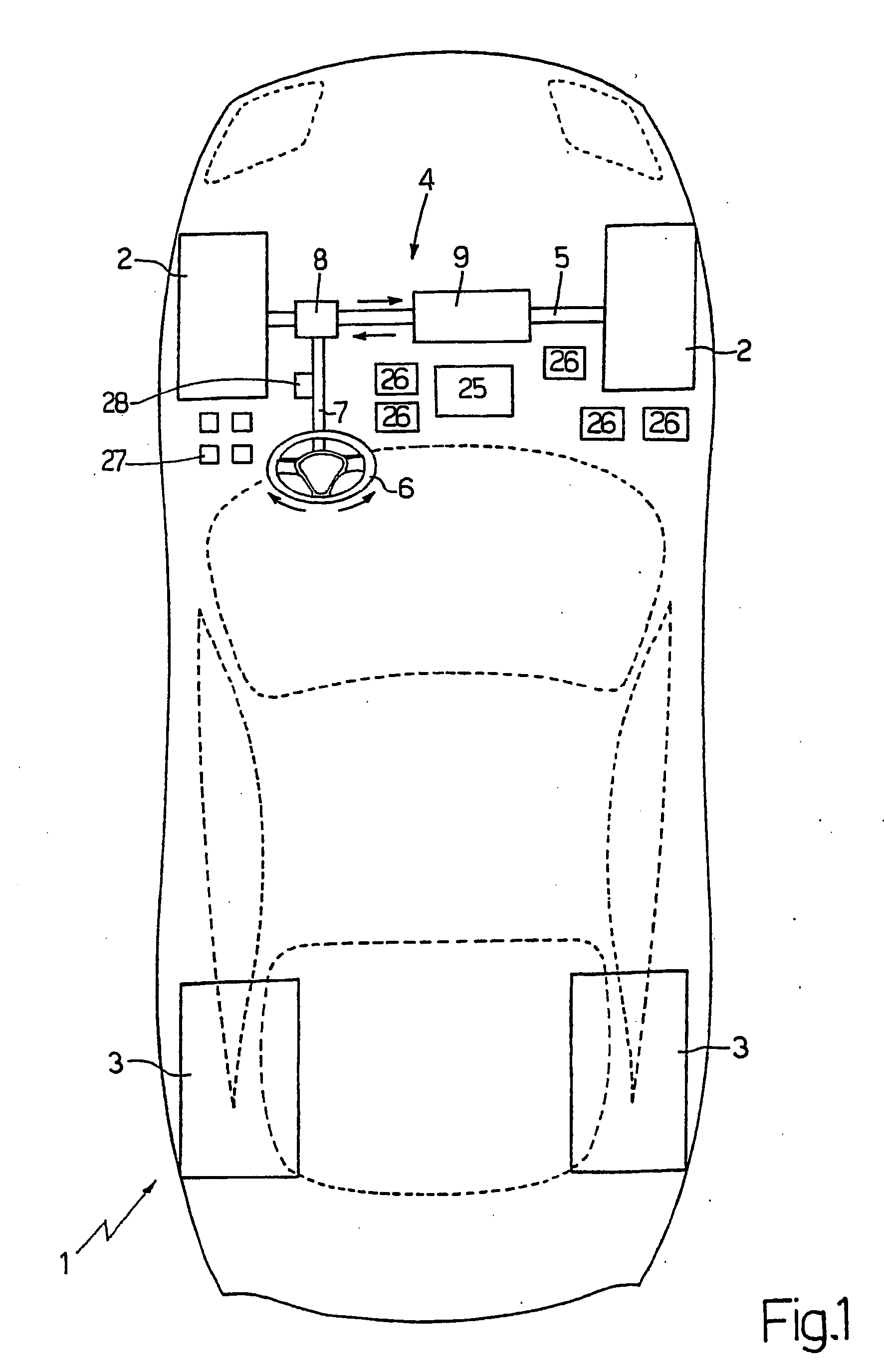
Figure 1 shows a schematic of a car equipped with a steering system in accordance
with the present invention;
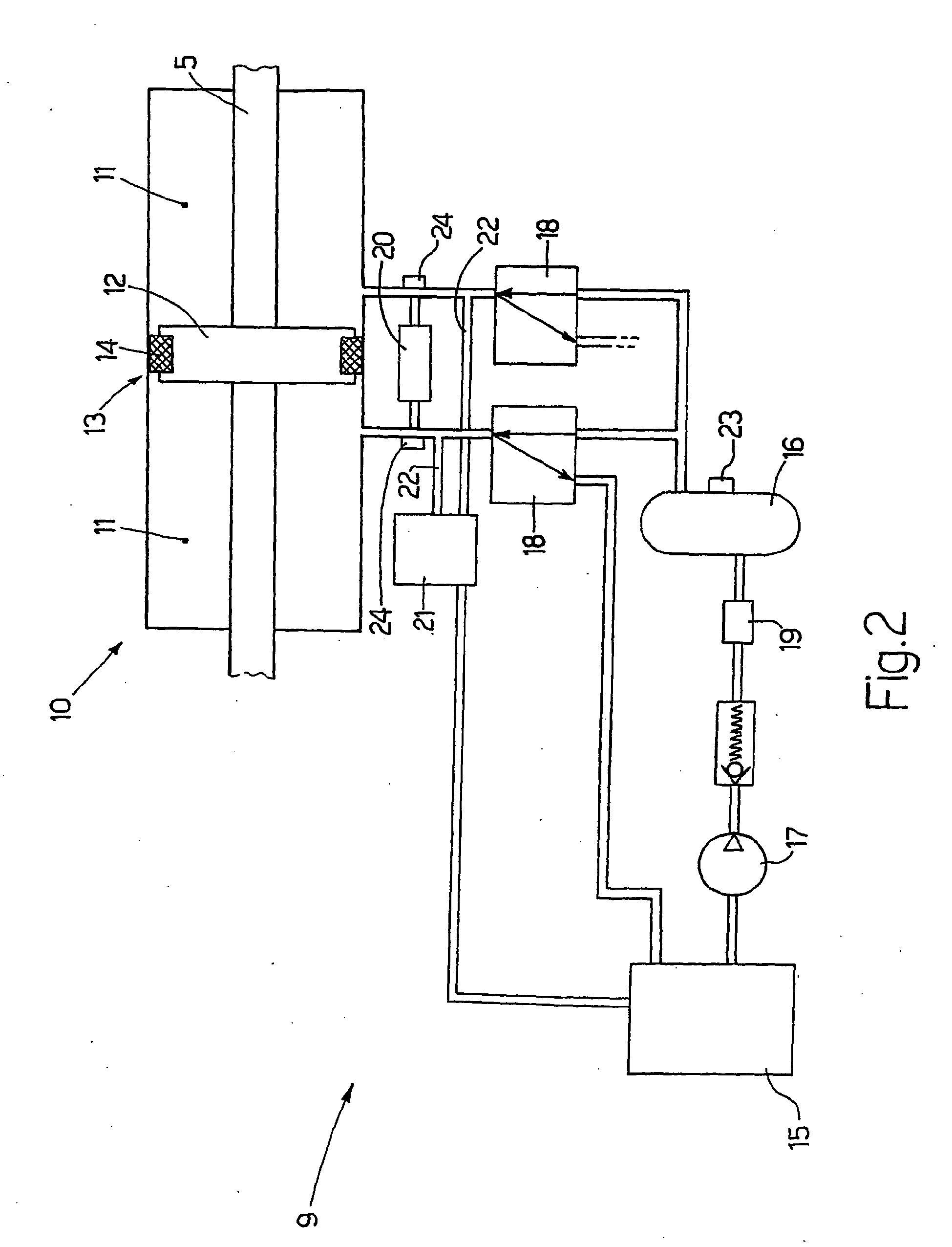
Figure 2 shows a schematic of a hydraulic power-assist device of the Figure 2 steering
system.
PREFERRED EMBODIMENTS OF THE INVENTION
[0010] Number 1 in Figure 1 indicates a rear-drive car comprising two front direction wheels
2 and two rear drive wheels 3. The turn angle of front direction wheels 2 is controlled
by a steering system 4 comprising a steering arm 5, which extends crosswise to car
1, is hinged at opposite ends to both front direction wheels 2, and is movable axially
by a steering wheel 6. More specifically, steering wheel 6 is fitted to a rotary steering
shaft 7 connected mechanically to steering arm 5 by a rack-and-pinion coupling device
8.
[0011] Steering system 4 also comprises a hydraulic power-assist (so-called "power steering")
device 9, which generates a variable force on steering arm 5 to reduce (or, more generally
speaking, modify) the torque exerted on steering wheel 6 to modify the turn angle
of front direction wheels 2.
[0012] As shown in Figure 2, hydraulic power-assist device 9 comprises a hydraulic actuator
10 located at an intermediate portion of steering arm 5, and which comprises two chambers
11 filled alternately with a pressurized fluid to move steering arm 5 axially in both
directions. More specifically, the two chambers 11 are fitted through with steering
arm 5, are located in series along steering arm 5, and are separated by a flange 12,
which is integral with steering arm 5, defines a piston of hydraulic actuator 10,
and comprises a central annular cavity 13 housing an annular seal 14.
[0013] Hydraulic power-assist device 9 also comprises a storage tank 15 containing the control
fluid (typically oil) of hydraulic actuator 10 at ambient pressure; a hydraulic accumulator
16 containing pressurized control fluid; a motor-driven pump 17, which draws control
fluid from storage tank 15 and pumps pressurized control fluid to hydraulic accumulator
16; and two proportional solenoid valves 18 for selectively connecting chambers 11
of hydraulic actuator 10 to storage tank 15 and hydraulic accumulator 16. More specifically,
each chamber 11 of hydraulic actuator 10 is associated with a respective three-way
solenoid valve 18, which isolates chamber 11 to maintain a constant amount of control
fluid inside chamber 11, connects chamber 11 to storage tank 15 to drain the control
fluid from chamber 11, or connects chamber 11 to hydraulic accumulator 16 to feed
control fluid into chamber 11.
[0014] Finally, hydraulic power-assist device 9 comprises a damp valve 20 located between
the two chambers 11 to prevent any fluctuations in pressure (hammering); and a safety
valve 21, which, in the event of a breakdown, connects both chambers 11 permanently
to storage tank 15 by means of respective bypass conduits 22.
[0015] Hydraulic accumulator 16 is fitted with a pressure sensor 23 for determining the
pressure of the fluid inside hydraulic accumulator 16; each chamber 11 is fitted with
a pressure sensor 24 for determining the pressure of the fluid inside chamber 11;
and pressure sensors 23 and 24 are connected to a control unit 25 for controlling
power-assist device 9. More specifically, hydraulic actuator 10 is feedback-controlled
by control unit 25 using the fluid pressures detected in chambers 11 by sensors 24
as feedback variables.
[0016] Car 1 is equipped with a number of electronic dynamic-performance control devices
26, which act on various active components (e.g. the engine and brakes) of car 1 to
alter the dynamic performance of car 1. More specifically, electronic dynamic-performance
control devices 26 comprise an ASR device for preventing spinning of rear drive wheels
3; an ABS (Anti Block System), which acts on the brake system to prevent locking of
wheels 2 and 3 when braking; an MSR device, which acts on the drive torque to prevent
rear drive wheels 3 from locking when braking; an E-diff (electronic differential
lock percentage control) device, and an ESP (Electronic Stability Program) device,
which limit swerving and excessive load transfer.
[0017] Control unit 25 is connected to electronic dynamic-performance control devices 26
(e.g. over a BUS of car 1) to real-time determine the status of electronic dynamic-performance
control devices 26. In other words, control unit 25 is able to determine whether,
and to what extent, an electronic dynamic-performance control device 26 is operating.
[0018] Control unit 25 is also connected to sensors 27 for real-time determining longitudinal
speed Vx, longitudinal acceleration Ax, transverse (or lateral) acceleration Ay, and
the swerve angle of car 1.
[0019] In a preferred embodiment, control unit 25 is also connected to a torque sensor 28
fitted to steering shaft 7 to determine the torque exerted by the user on steering
wheel 6.
[0020] In actual use, control unit 25 determines operation of electronic dynamic-performance
control devices 26, and modifies the power-assist torque accordingly.
[0021] When the ESP device indicates car 1 is close to its road-holding limit, control unit
25 may increase the power-assist torque to alert the driver accordingly in advance
by increasing natural "slackening" of steering wheel 6 in advance. This control mode
is better suited to non-professional drivers, whose main concern is safety, as opposed
to pushing the car to its extreme limit. Conversely, when the ESP device indicates
car 1 is close to its road-holding limit, control unit 25 may reduce the power-assist
torque to counteract natural "slackening" of steering wheel 6. This control mode is
better suited to professional drivers, whose main concern is pushing the car to its
extreme limit, as opposed to safety.
[0022] On determining operation of the E-diff (electronic differential lock percentage control)
device, control unit 25 may introduce into the power-assist torque a pulsating (i.e.
time-variable) component of a frequency discernible by the driver (e.g. 1-5 Hz) and
of low enough intensity (5-10% of the total) not to affect driving. The purpose of
the pulsating component is to alert the driver to operation of the E-diff device,
and to the fact that car 1 is nearing a limit, both of which, without the pulsating
component, could go unnoticed by the driver (particularly a non-professional driver).
[0023] By means of sensors 27, control unit 25 also determines speed Vx, accelerations Ax
and Ay, and the swerve angle of car 1, and modifies the power-assist torque accordingly.
[0024] Finally, by means of sensor 28, control unit 25 determines the torque exerted by
the driver on steering wheel 6, and modifies the power-assist torque accordingly.
[0025] In other words, the final power-assist torque exerted on steering arm 5 depends on
operation (if any) of electronic dynamic-performance control devices 26, on speed
Vx, accelerations Ax and Ay, and the swerve angle of car 1, and on the torque exerted
by the driver on steering wheel 6. In a preferred embodiment, the final power-assist
torque exerted on steering arm 5 is largely determined (80-90%) on the basis of speed
Vx of car 1, and is corrected slightly (10-20%) as a function of accelerations Ax
and Ay of car 1, the swerve angle of car 1, operation (if any) of electronic dynamic-performance
control devices 26, and the torque exerted by the driver on steering wheel 6.
[0026] As will be clear from the above description, hydraulic power-assist device 9 provides
for "variable torque feedback" on steering wheel 6 of car 1. The variation in feedback
is regulated by control unit 25 by means of hydraulic actuator 10, and is determined
on the basis of the causes (e.g. ABS, MSR, E-diff, ESP intervention) and effects (speed,
turn angle, accelerations, swerve angle) affecting dynamic performance of car 1.
1. A steering system (4) for a car (1) having two front direction wheels (2) and a number
of electronic dynamic-performance control devices (26) including an ESP device for
controlling stability of the car; the steering system (4) comprising:
a steering wheel (6) for controlling a turn angle of the front direction wheels (2);
and
a power-assist device (9), which generates a power-assist torque which is added to
the torque exerted on the steering wheel (6) to vary the turn angle of the front direction
wheels (2);
wherein the power-assist device (9) comprises a control unit (25), which determines
operation of the electronic dynamic-performance control devices (26), and modifies
the power-assist torque as a function of operation of the electronic dynamic-performance
control devices (26);
the steering system (4) being
characterized in comprising:
a control mode for non-professional drivers whose main concern is safety as opposed
to pushing the car to its extreme limit, in which, when the ESP device indicates the
car (1) is close to its road-holding limit, the control unit (25) increases the power-assist
torque to alert the driver accordingly in advance by increasing natural "slackening"
of the steering wheel (6) in advance; and
a control mode for professional drivers whose main concern is pushing the car to its
extreme limit, as opposed to safety, in which, when the ESP device indicates the car
(1) is close to its road-holding limit, the control unit (25) reduces the power-assist
torque to counteract natural "slackening of the steering wheel (6).
2. A steering system (4) as claimed in Claim 1, wherein the electronic dynamic-performance
control devices (26) comprise an ASR device for preventing spinning of the drive wheels
(3); an ABS device, which acts on the brake system to prevent locking of the wheels
(2, 3) when braking; an MSR device, which acts on the drive torque to prevent the
drive wheels (3) from locking when braking; and an E-diff device for electronically
controlling the lock percentage of a differential.
3. A steering system (4) as claimed in Claim 1 or 2, wherein the control unit (25) is
connected to the electronic dynamic-performance control devices (26) over a BUS of
the car (1) to real-time determine the status of the electronic dynamic-performance
control devices (26).
4. A steering system (4) as claimed in one of Claims 1 to 3, wherein, when the control
unit (25) determines operation of an E-diff device for electronically controlling
the lock percentage of a differential, the control unit (25) introduces into the power-assist
torque a pulsating component of a frequency discernable by the driver and of low intensity.
5. A steering system (4) as claimed in one of Claims 1 to 4, wherein the control unit
(25) is connected to sensors (27) for real-time determining the longitudinal speed
Vx, longitudinal acceleration Ax, transverse acceleration Ay, and swerve angle of
the car (1), the control unit (25) determines the speed Vx, accelerations Ax and Ay,
and swerve angle of the car (1) by means of the sensors (27), and modifies the power-assist
torque as a function of the speed Vx, accelerations Ax and Ay, and swerve angle of
the car (1).
6. A steering system (4) as claimed in one of Claims 1 to 5, wherein the control unit
(25) is connected to a torque sensor (28) connected to a steering shaft (7) to determine
the torque exerted by the driver on the steering wheel (6); the control unit (25)
determines the torque exerted by the driver on the steering wheel (6) by means of
the torque sensor (28), and modifies the power-assist torque as a function of the
torque applied by the driver on the steering wheel (6).
7. A steering system (4) as claimed in one of Claims 1 to 6, wherein the power-assist
device (9) comprises a hydraulic actuator (10) located at an intermediate portion
of the steering arm (5), and which comprises two chambers (11) filled alternately
with a pressurized fluid to move the steering arm (5) axially in both directions.
8. A steering system (4) as claimed in Claim 7, wherein the two chambers (11) are fitted
through with the steering arm (5), are arranged in series along the steering arm (5),
and are separated by a flange (12), which is integral with the steering arm (5) and
defines a piston of the hydraulic actuator (10).
9. A steering system (4) as claimed in Claim 7 or 8, wherein the power-assist device
(9) comprises a storage tank (15) containing the control fluid of the hydraulic actuator
(10) at ambient pressure; a hydraulic accumulator (16) containing pressurized control
fluid; a motor-driven pump (17) which draws control fluid from the storage tank (15)
and pumps pressurized control fluid to the hydraulic accumulator (16); and two proportional
solenoid valves (18) for selectively connecting the chambers (11) of the hydraulic
actuator (10) to the storage tank (15) and the hydraulic accumulator (16).
10. A steering system (4) as claimed in Claim 9, wherein the power-assist device (9) comprises
a damp valve (20) located between the two chambers (11) to prevent fluctuations in
pressure.
11. A steering system (4) as claimed in Claim 9 or 10, wherein the power-assist device
(9) comprises a safety valve (21), which, in the event of a breakdown, connects the
two chambers (11) permanently to the storage tank (15) by means of respective bypass
conduits (22).
12. A steering system (4) as claimed in one of Claims 9 to 11, wherein the hydraulic accumulator
(16) is fitted with a first pressure sensor (23) for determining the pressure of the
fluid in the hydraulic accumulator (16); and each chamber (11) is fitted with a second
pressure sensor (24) for determining the pressure of the fluid in the chamber (11).
13. A steering system (4) as claimed in Claim 12, wherein the control unit (25) controls
the power-assist device (9), and is connected to the second pressure sensors (24);
and the hydraulic actuator (10) is feedback-controlled by the control unit (25) using
the fluid pressures detected inside the chambers (11) by the second pressure sensors
(24) as feedback variables.
1. Lenksystem (4) für ein Auto (1) mit zwei Vorderrädern (2) und einer Anzahl elektronischer
Fahrdynamik-Leistungssteuervorrichtungen (26), die eine ESP-Vorrichtung zur Kontrolle
der Stabilität des Autos aufweisen; wobei das Lenksystem (4) aufweist:
ein Lenkrad (6) zur Kontrolle eines Einschlagwinkels der Vorderräder (2); und
eine Servovorrichtung (9), die ein Servodrehmoment erzeugt, das zum Drehmoment addiert
wird, das auf das Lenkrad (6) ausgeübt wird, um den Einschlagwinkel der Vorderräder
(2) zu verändern;
wobei die Servovorrichtung (9) eine Steuereinheit (25) aufweist, die den Betrieb der
elektronischen Fahrdynamik-Leistungssteuervorrichtungen (26) bestimmt, und das Servodrehmoment
als Funktion des Betriebs der elektronischen Fahrdynamik-Leistungssteuervorrichtungen
(26) modifiziert;
wobei das Lenksystem (4)
dadurch gekennzeichnet ist, dass es aufweist:
eine Steuerungsbetriebsart für Nicht-Profifahrer, deren Hauptanliegen Sicherheit ist,
anstatt das Auto an seine äußersten Grenzen zu treiben, in der, wenn die ESP-Vorrichtung
anzeigt, dass das Auto (1) nahe seiner Straßenhaftungsgrenze ist, die Steuereinheit
(25) das Servodrehmoment erhöht, um den Fahrer folglich im voraus zu alarmieren, indem
das natürliche "Nachgeben" des Lenkrads (6) im voraus erhöht wird; und
eine Steuerungsbetriebsart für Profifahrer, deren Hauptanliegen anstelle von Sicherheit
es ist, das Auto an seine äußersten Grenzen zu treiben, in der, wenn die ESP-Vorrichtung
anzeigt, dass das Auto (1) nahe seiner Straßenhaftungsgrenze ist, die Steuereinheit
(25) das Servodrehmoment reduziert, um dem natürlichen "Nachgeben" des Lenkrads (6)
entgegenzuwirken.
2. Lenksystem (4) nach Anspruch 1, wobei die elektronischen Fahrdynamik-Leistungssteuervorrichtungen
(26) aufweisen: eine ASR-Vorrichtung zur Verhinderung des Durchdrehens der Antriebsräder
(3); eine ABS-Vorrichtung, die auf das Bremssystem wirkt, um das Blockieren der Räder
(2, 3) beim Bremsen zu verhindern; eine MSR-Vorrichtung, die auf das Antriebsdrehmoment
wirkt, um das Blockieren der Antriebsräder (3) beim Bremsen zu verhindern; und eine
E-diff-Vorrichtung zur elektronischen Steuerung des Sperrprozentsatzes eines Differentials.
3. Lenksystem (4) nach Anspruch 1 oder 2, wobei die Steuereinheit (25) über einen BUS
des Autos (1) mit den elektronischen Fahrdynamik-Leistungssteuervorrichtungen (26)
verbunden ist, um in Echtzeit den Status der elektronischen Fahrdynamik-Leistungssteuervorrichtungen
(26) festzustellen.
4. Lenksystem (4) nach einem der Ansprüche 1 bis 3, wobei, wenn die Steuereinheit (25)
den Betrieb einer E-diff-Vorrichtung zur elektronischen Steuerung des Sperrprozentsatzes
eines Differentials feststellt, die Steuereinheit (25) in das Servodrehmoment eine
pulsierende Komponente mit einer durch den Fahrer wahrnehmbaren Frequenz und mit niedriger
Intensität einführt.
5. Lenksystem (4) nach einem der Ansprüche 1 bis 4, wobei die Steuereinheit (25) zur
Echtzeitbestimmung der Längsgeschwindigkeit Vx, der Längsbeschleunigung Ax, der Querbeschleunigung
Ay und des Gierwinkels des Autos (1) mit Sensoren (27) verbunden ist, die Steuereinheit
(25) die Geschwindigkeit Vx, die Beschleunigungen Ax und Ay und den Gierwinkel des
Autos (1) mittels der Sensoren (27) bestimmt und das Servodrehmoment als Funktion
der Geschwindigkeit Vx, der Beschleunigungen Ax und Ay und des Gierwinkels des Autos
(1) modifiziert.
6. Lenksystem (4) nach einem der Ansprüche 1 bis 5, wobei die Steuereinheit (25) mit
einem Drehmomentsensor (28) verbunden ist, der mit einer Lenkwelle (7) verbunden ist,
um das durch den Fahrer auf das Lenkrad (6) ausgeübte Drehmoment zu bestimmen; die
Steuereinheit (25) das durch den Fahrer auf das Lenkrad (6) ausgeübte Drehmoment mittels
des Drehmomentsensors (28) bestimmt und das Servodrehmoment als Funktion des durch
den Fahrer auf das Lenkrad (6) ausgeübten Drehmoments modifiziert.
7. Lenksystem (4) nach einem der Ansprüche 1 bis 6, wobei die Servovorrichtung (9) einen
Hydraulikaktor (10) aufweist, der an einem Zwischenabschnitt des Spurstangenhebels
(5) angeordnet ist und der zwei Kammern (11) aufweist, die abwechselnd mit einer Druckflüssigkeit
gefüllt werden, um den Spurstangenhebel (5) axial in beide Richtungen zu bewegen.
8. Lenksystem (4) nach Anspruch 7, wobei die beiden Kammern (11) mit dem durch sie hindurch
gehenden Spurstangenhebel (5) versehen sind, in Reihe längs des Spurstangenhebels
(5) angeordnet sind, und durch einen Flansch (12) getrennt sind, der mit dem Spurstangenhebel
(5) integral ist und einen Kolben des Hydraulikaktors (10) definiert.
9. Lenksystem (4) nach Anspruch 7 oder 8, wobei die Servovorrichtung (9) aufweist: einen
Vorratstank (15), der die Steuerflüssigkeit des Hydraulikaktors (10) unter Umgebungsdruck
enthält; einen Hydraulikdruckspeicher (16), der Drucksteuerflüssigkeit enthält; eine
motorbetriebene Pumpe (17), die Steuerflüssigkeit aus dem Vorratstank (15) saugt und
Drucksteuerflüssigkeit zum Hydraulikdruckspeicher (16) pumpt; und zwei Proportionalmagnetventile
(18) zur selektiven Verbindung der Kammern (11) des Hydraulikaktors (10) mit dem Vorratstank
(15) und dem Hydraulikdruckspeicher (16).
10. Lenksystem (4) nach Anspruch 9, wobei die Servovorrichtung (9) ein Dämpfungsventil
(20) aufweist, das zwischen den beiden Kammern (11) angeordnet ist, um Druckschwankungen
zu verhindern.
11. Lenksystem (4) nach Anspruch 9 oder 10, wobei die Servovorrichtung (9) ein Sicherheitsventil
(21) aufweist, das im Fall einer Betriebsstörung die beiden Kammern (11) mittels jeweiliger
Umgehungskanäle (22) dauerhaft mit dem Vorratstank (15) verbindet.
12. Lenksystem (4) nach einem der Ansprüche 9 bis 11, wobei der Hydraulikdruckspeicher
(16) zur Bestimmung des Drucks der Flüssigkeit im Hydraulikdruckspeicher (16) mit
einem ersten Drucksensor (23) versehen ist; und jede Kammer (11) zur Bestimmung des
Drucks der Flüssigkeit in der Kammer (11) mit einem zweiten Drucksensor (24) versehen
ist.
13. Lenksystem (4) nach Anspruch 12, wobei die Steuereinheit (25) die Servovorrichtung
(9) steuert und mit den zweiten Drucksensoren (24) verbunden ist; und der Hydraulikaktor
(10) durch die Steuereinheit (25) mittels der Flüssigkeitsdrücke, die innerhalb der
Kammern (11) durch die zweiten Drucksensoren (24) als Rückkopplungsvariablen ermittelt
werden, rückkopplungsgesteuert wird.
1. Système de direction (4) pour une automobile (1) comportant deux roues de direction
avant (2) et un certain nombre de dispositifs de commande de performances dynamiques
électroniques (26) comprenant un dispositif de programme de stabilité électronique
(ESP) pour contrôler la stabilité de l'automobile ; le système de direction (4) comprenant
:
un volant de direction (6) pour commander un angle de braquage des roues de direction
avant (2) ; et
un dispositif d'assistance de puissance (9), qui génère un couple d'assistance de
puissance qui est ajouté au couple exercé sur le volant de direction (6) de façon
à faire varier l'angle de braquage des roues de direction avant (2) ;
dans lequel le dispositif d'assistance de puissance (9) comprend une unité de commande
(25), qui détermine le fonctionnement des dispositifs de commande de performances
dynamiques électroniques (26), et qui modifie le couple d'assistance de puissance
en fonction du fonctionnement des dispositifs de commande de performances dynamiques
électroniques (26) ;
le système de direction (4) étant
caractérisé en ce qu'il comprend :
un mode de commande pour des conducteurs non professionnels dont le souci principal
est la sécurité, par opposition au fait de pousser l'automobile à ses limites extrêmes,
dans lequel, lorsque le dispositif de programme de stabilité électronique indique
que l'automobile (1) est proche de sa limite de tenue de route, l'unité de commande
(25) augmente le couple d'assistance de puissance de façon à alerter par conséquent
à l'avance le conducteur par l'augmentation à l'avance d'un "mou" naturel du volant
de direction (6) ; et
un mode de commande pour des conducteurs professionnels dont le souci principal est
de pousser l'automobile à ses limites extrêmes, par opposition à la sécurité, dans
lequel, lorsque le dispositif de programme de stabilité électronique indique que l'automobile
(1) est proche de sa limite de tenue de route, l'unité de commande (25) réduit le
couple d'assistance de puissance de façon à contrecarrer le "mou" naturel du volant
de direction (6).
2. Système de direction (4) selon la revendication 1, dans lequel les dispositifs de
commande de performances dynamiques électroniques (26) comprennent un dispositif de
régulation de patinage d'accélération (ASR) pour empêcher le patinage des roues d'entraînement
(3) ; un dispositif de système anti-blocage (ABS), qui agit sur le système de frein
de façon à empêcher le blocage des roues (2, 3) lors du freinage ; un dispositif de
régulation de moment de couple (MSR), qui agit sur le couple d'entraînement de façon
à empêcher les roues d'entraînement (3) de se bloquer lors du freinage ; et un dispositif
de commande de pourcentage de blocage de différentiel électronique (E-diff) pour commander
électroniquement le pourcentage de blocage d'un différentiel.
3. Système de direction (4) selon la revendication 1 ou 2, dans lequel l'unité de commande
(25) est connectée aux dispositifs de commande de performances dynamiques électroniques
(26) sur un bus de l'automobile (1) de façon à déterminer en temps réel l'état des
dispositifs de commande de performances dynamiques électroniques (26).
4. Système de direction (4) selon l'une des revendications 1 à 3, dans lequel, lorsque
l'unité de commande (25) détermine le fonctionnement d'un dispositif E-diff pour commander
électroniquement le pourcentage de blocage d'un différentiel, l'unité de commande
(25) introduit dans le couple d'assistance de puissance une composante pulsée d'une
fréquence pouvant être discernée par le conducteur et de faible intensité.
5. Système de direction (4) selon l'une quelconque des revendications 1 à 4, dans lequel
l'unité de commande (25) est connectée à des capteurs (27) pour déterminer en temps
réel la vitesse longitudinale Vx, l'accélération longitudinale Ax, l'accélération
transversale Ay, et l'angle de dérapage de l'automobile (1) ; l'unité de commande
(25) détermine la vitesse Vx, les accélérations Ax et Ay, et l'angle de dérapage de
l'automobile (1) à l'aide des capteurs (27), et modifie le couple d'assistance de
puissance en fonction de la vitesse Vx, des accélérations Ax et Ay, et de l'angle
de dérapage de l'automobile (1).
6. Système de direction (4) selon l'une des revendications 1 à 5, dans lequel l'unité
de commande (25) est connectée à un capteur de couple (28) relié à un arbre de direction
(7) de façon à déterminer le couple exercé par le conducteur sur le volant de direction
(6) ; l'unité de commande (25) détermine le couple exercé par le conducteur sur le
volant de direction à l'aide du capteur de couple (28), et modifie le couple d'assistance
de puissance en fonction du couple appliqué par le conducteur sur le volant de direction
(6).
7. Système de direction (4) selon l'une des revendications 1 à 6, dans lequel le dispositif
d'assistance de puissance (9) comprend un actionneur hydraulique (10) disposé en une
partie intermédiaire du bras de direction (5), et qui comprend deux chambres (11)
remplies en alternance d'un fluide sous pression pour déplacer le bras de direction
(5) axialement dans les deux directions.
8. Système de direction (4) selon la revendication 7, dans lequel les deux chambres (11)
sont munies à travers celles-ci du bras de direction (5), celles-ci sont disposées
en série le long du bras de direction (5), et elles sont séparées par un flasque (12),
qui est intégré au bras de direction et qui définit un piston de l'actionneur hydraulique
(10).
9. Système de direction (4) selon la revendication 7 ou 8, dans lequel le dispositif
d'assistance de puissance (9) comprend un réservoir de stockage (15) contenant le
fluide de commande de l'actionneur hydraulique (10) à la pression ambiante ; un accumulateur
hydraulique (16) contenant un fluide de commande sous pression ; une pompe actionnée
par un moteur (17) qui aspire le fluide de commande à partir du réservoir de stockage
(15) et qui pompe le fluide de commande sous pression vers l'accumulateur hydraulique
(16) ; et deux électrovannes proportionnelles (18) pour relier de façon sélective
les chambres (11) de l'actionneur hydraulique (10) au réservoir de stockage (15) et
à l'accumulateur hydraulique (16).
10. Système de direction (4) selon la revendication 9, dans lequel le dispositif d'assistance
de puissance (9) comprend une soupape de décharge (20) disposée entre les deux chambres
(11) afin d'éviter des fluctuations de pression.
11. Système de direction (4) selon la revendication 9 ou 10, dans lequel le dispositif
d'assistance de puissance (9) comprend une soupape de sûreté (21), qui, dans le cas
d'une panne, relie les deux chambres (11) de façon permanente au réservoir de stockage
(15) à l'aide de conduits de dérivation respectifs (22).
12. Système de direction (4) selon l'une des revendications 9 à 11, dans lequel l'accumulateur
hydraulique (16) est muni d'un premier capteur de pression (23) afin de déterminer
la pression du fluide dans l'accumulateur hydraulique (16) ; et chaque chambre (11)
est munie d'un deuxième capteur de pression (24) afin de déterminer la pression du
fluide dans la chambre (11).
13. Système de direction (4) selon la revendication 12, dans lequel l'unité de commande
(25) commande le dispositif d'assistance de puissance (9), et est connectée aux deuxièmes
capteurs de pression ; et l'actionneur hydraulique (10) est commandé en rétroaction
par l'unité de commande (25) à l'aide des pressions de fluide détectées à l'intérieur
des chambres (11) par les deuxièmes capteurs de pression (24), qui constituent des
variables de rétroaction.
REFERENCES CITED IN THE DESCRIPTION
This list of references cited by the applicant is for the reader's convenience only.
It does not form part of the European patent document. Even though great care has
been taken in compiling the references, errors or omissions cannot be excluded and
the EPO disclaims all liability in this regard.
Patent documents cited in the description