| (19) |
 |
|
(11) |
EP 2 380 752 B1 |
| (12) |
EUROPEAN PATENT SPECIFICATION |
| (45) |
Mention of the grant of the patent: |
|
26.06.2013 Bulletin 2013/26 |
| (22) |
Date of filing: 18.04.2011 |
|
| (51) |
International Patent Classification (IPC):
|
|
| (54) |
An asymmetrical wheel hub assembly
Asymmetrische Radnabenanordnung
Ensemble moyeu de roue asymmetrique
|
| (84) |
Designated Contracting States: |
|
AL AT BE BG CH CY CZ DE DK EE ES FI FR GB GR HR HU IE IS IT LI LT LU LV MC MK MT NL
NO PL PT RO RS SE SI SK SM TR |
| (30) |
Priority: |
20.04.2010 IT TO20100329
|
| (43) |
Date of publication of application: |
|
26.10.2011 Bulletin 2011/43 |
| (73) |
Proprietor: Aktiebolaget SKF |
|
415 50 Göteborg (SE) |
|
| (72) |
Inventor: |
|
- Ciulla, Luca
I-10137, TORINO (IT)
|
| (74) |
Representative: Fioravanti, Corrado et al |
|
Jacobacci & Partners S.p.A.
Corso Emilia 8
10152 Torino
10152 Torino (IT) |
| (56) |
References cited: :
EP-A2- 1 722 115
US-A1- 2005 111 771
US-A1- 2009 232 435
|
WO-A1-2005/008085
US-A1- 2009 052 823
|
|
| |
|
|
|
|
| |
|
| Note: Within nine months from the publication of the mention of the grant of the European
patent, any person may give notice to the European Patent Office of opposition to
the European patent
granted. Notice of opposition shall be filed in a written reasoned statement. It shall
not be deemed to
have been filed until the opposition fee has been paid. (Art. 99(1) European Patent
Convention).
|
[0001] The present invention relates to an asymmetrical wheel hub assembly.
[0002] Asymmetrical wheel hub assemblies of the known type have an axis of rotation and
comprise two rows of rolling bodies with pitch diameters of dimensions that differ
from one another, an inner flanged ring and an outer ring arranged coaxially with
and externally to the inner ring and, for each row of rolling bodies, an inner raceway
and an outer raceway obtained, respectively, on the outside of the inner ring and
on the inside of the outer ring in positions axially staggered with respect to one
another to permit the asymmetrical wheel hub assembly to support combined loads, i.e.
loads that act simultaneously in a radial direction and in an axial direction.
[0003] With asymmetrical wheel hub assemblies of the type described above, the dimension
of the pitch diameter of the row of rolling bodies arranged closest to a flange of
the inner flanged ring, i.e. of the row of rolling bodies arranged on the so-called
"outboard" side, is greater than the dimension of a diameter of the other row of rolling
bodies, i.e. of the row of rolling bodies arranged on the so-called "inboard" side.
The geometry just described confers greater rigidity on the asymmetrical wheel hub
assembly, especially if compared with a symmetrical wheel hub assembly in which both
pitch diameters are identical and their dimensions are the same as the dimensions
of the row of rolling bodies on the "inboard" side.
[0004] Asymmetrical wheel hub assemblies are used in countless applications in the automobile
field, but because of the increasingly restrictive anti-pollution regulations that
have come into effect in recent years, it has been necessary to study technological
solutions aimed, even indirectly, at reducing both the energy consumption of the vehicles
and emissions noxious for the environment such as, for example, carbon monoxide emissions.
[0005] US 2009/0232435 A1 discloses a wheel hub assembly as defined in the preamble of claim 1.
[0006] The object of the present invention is to provide an asymmetrical wheel hub assembly
which, while maintaining high mechanical characteristics and high rigidity, as well
as high reliability, permits a significant reduction of consumption and of pollutant
emissions.
[0007] According to the present invention, there is provided an asymmetrical wheel hub assembly
having the features set forth in claim 1. Preferred embodiments are defined in the
dependent claims.
[0008] The invention will now be described with reference to the attached drawings which
illustrate some non-limitating exemplary embodiments, in which:
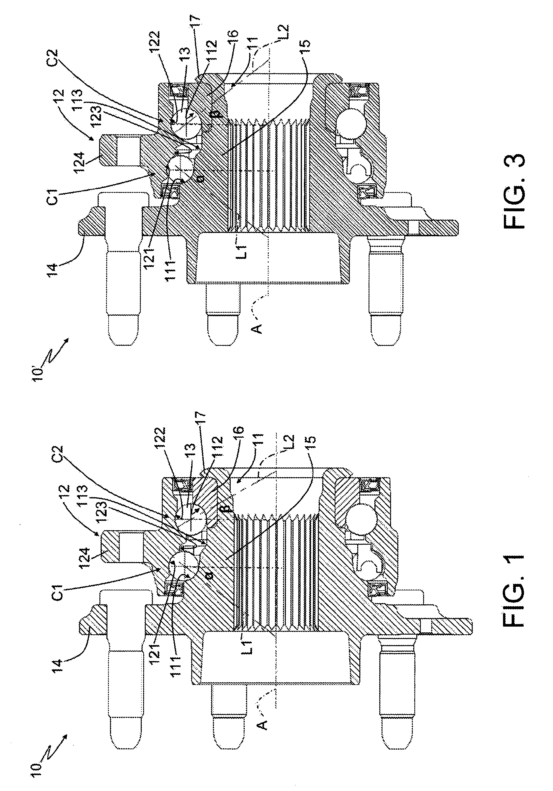
- figure 1 illustrates, in cross section, a first preferred embodiment of an asymmetrical
wheel hub assembly made according to this invention;
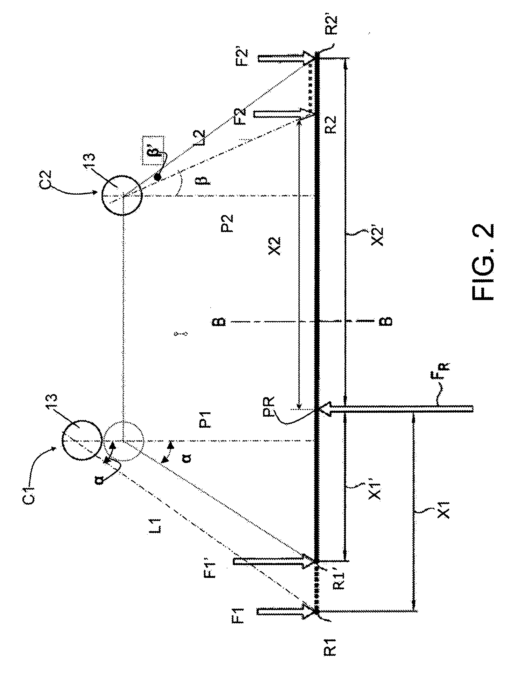
- figure 2 is a schematic diagram of the distribution of the loads of the wheel hub
assembly in figure 1;
- figure 3 illustrates, in cross section, a second preferred embodiment of an asymmetrical
wheel hub assembly of figure 1.
[0009] With reference to figure 1, 10 indicates an asymmetrical wheel hub assembly as a
whole with an axis A of rotation and comprising an inner ring 11 and an outer ring
12 coaxial with respect to one another and to the axis A of rotation and revolving
with respect to one another because of the interposition between them of two rows
C1, C2 of rolling bodies 13. In the example described here, the rolling bodies 13
are balls, the centres of which are arranged along respective pitch diameters P1,
P2. In the exemplary embodiment illustrated, the dimensions of the pitch diameter
P1 of the row C1 are greater than the dimensions of the pitch diameter P2 of the row
C2.
[0010] Furthermore, the assembly 10 comprises, for each row C1 and C2, an inner raceway
111, 112 and an outer raceway 121, 122 arranged in axially staggered positions to
permit the assembly 10 to support combined loads, which act simultaneously both in
the radial direction and in the axial direction, and are transmitted between balls
13 and inner raceways 111, 112 and between balls 13 and outer raceways 121, 122 along
respective load lines L1, L2. In particular, the load lines L1, L2 join the points
of contact between the balls 13 of each row C1, C2 with the associated inner raceways
111, 112 and the associated outer raceways 121, 122, and form respective angles α
and β of contact with respective lines perpendicular to the axis A in a radial plane.
[0011] The inner raceways 111, 112 are obtained outside the inner ring 11, while the outer
raceways 121, 122 are obtained directly on an inner surface 123 of the outer ring
12 which, in the exemplary embodiment illustrated, is provided with an outer flange
124 for anchoring the assembly 10 to a vehicle.
[0012] The inner ring 11 is an inner flanged ring to permit the attachment of a wheel to
the assembly 10, and comprises:
- a flange 14 transversal to the axis A of rotation,
- a spindle 15 that extends along the axis A of rotation and is made of the same material
as the flange 14, and
- an applied inner ring 16, which is fitted on the spindle 15, and is axially blocked
by a rolled edge 17.
[0013] The flange 14 and the ring 16 define, for the assembly 10, the so-called "outboard
side" and, respectively, the "inboard side", and the inner raceway 111 of the row
C1 is obtained directly on an outer surface 113 of the spindle 15 in the vicinity
of the flange 14, while the inner raceway 112 of the row C2 is obtained directly on
the applied ring 16. Alternatively, according to a form of embodiment that is not
illustrated, the inner raceway 111 of row C1 can be obtained directly on a respective
applied ring arranged in an intermediate position between the flange 14 and the ring
16 and axially blocked by the flange 14 and ring 16.
[0014] The raceways 111, 112, 121, 122 have respective osculations O
xy defined by the ratio between the radiuses r of curvature of the raceways 111, 112,
121, 122 and the outer diameters Φ 1, Φ2 of the balls 13 of each row C1, C2. In other
words, the following osculations are obtained:
OOE: ratio between the radius of curvature of the outer raceway 111, outboard side, with
the outer diameter Φ1;
OIE: ratio between the radius of curvature of the outer raceway 112, inboard side, and
the outer diameter Φ2;
OOI: ratio between the radius of curvature of the inner raceway 121, outboard side, and
the outer diameter Φ1;
OII: ratio between the radius of curvature of the inner raceway 122, inboard side, and
the outer diameter Φ2;
[0015] In the example of embodiment illustrated, for the purpose of reducing slipping between
the balls 13 and the associated raceways 111, 112, 121, 122, i.e. for the purpose
of reducing the friction between rolling bodies and raceways and, as a consequence,
for the purpose of reducing a possible source of dissipation of energy or for the
purpose of reducing consumption and pollutant emissions, in the wheel hub assembly
10, the osculations O
OE, O
OI of the row C1 are different from the respective osculations O
IE, O
II of the row C2. The best performance in terms of reduction of friction is obtained
when the wheel hub assembly 10 is made according to any one of the following geometrical
conditions:
- 1) OOE > OIE; or
- 2) OOI > OII; or
- 3) OOE > OIE and OOI > OII.
[0016] In particular, it was found that the optimum conditions in terms of reduction of
friction are obtained when the wheel hub assembly 10 is made according to any one
of the following geometrical conditions:
- 1) OOE > 1.004 OIE; or
- 2) OOI > 1.004 OII; or
- 3) OOE > 1.004 OIE and OOI > 1.004 OII.
[0017] The different osculation of the outboard side compared with the inboard side can
be obtained both by varying the radiuses of curvature of the associated raceways 111,
121 of the outboard side compared with the radiuses of curvature of the raceways of
the inboard side, or by varying the outer diameters Φ1, Φ2 of the balls 13.
[0018] In other words, the different osculation of the outboard side compared with the inboard
side can be obtained by making a wheel hub assembly 10' as alternatively illustrated
in figure 3, in which the outer diameters Φ1 of the balls 13 of the row C1 do not
have the same dimensions as the dimensions of the outer diameters Φ2 of the balls
13 of the row C2, as in the example of embodiment described above, but in which the
outer diameters Φ1 of the balls 13 of the row C1 have smaller dimensions than those
of the outer diameters Φ2 of the balls 13 of the row C2.
[0019] The reduction of the outer diameters Φ1 of the balls 13 entails, with the same dynamic
and structural conditions described above, a reduction of the tangential velocity
between the balls 13 and raceways and, therefore, a reduction of the friction.
[0020] In addition to the beneficial effects in terms of reduction of the friction between
rolling bodies and raceways as described above as an effect of the ratios between
the osculations, and again with the same reduction aims, the wheel hub assembly 10
described above, just like the wheel hub assembly 10' with balls 13 of different outer
diameters, also has magnitudes of the angles of contact α, β with dimensions that
differ from one another and, in particular, the angle of contact α of the row C1 has
a greater magnitude than the magnitude of the contact angle β of the row C2.
[0021] Figure 2 provides a schematic illustration of the load diagram of the wheel hub assembly
10 of this invention in the case in which it is subjected to a wheel load FR applied
in correspondence with the centre PR of application arranged along the axis A of rotation.
[0022] The rows C1, C2 of the wheel hub assembly 10, subjected to the wheel load FR, react
with respective forces F1, .F2 of reaction, which are applied in correspondence with
the respective centres R1, R2 of reaction which are identified along the axis A of
intersection of the associated lines L1, L2 of force with the axis A, and are at axial
distances X1, X2 respectively from the centre PR of application.
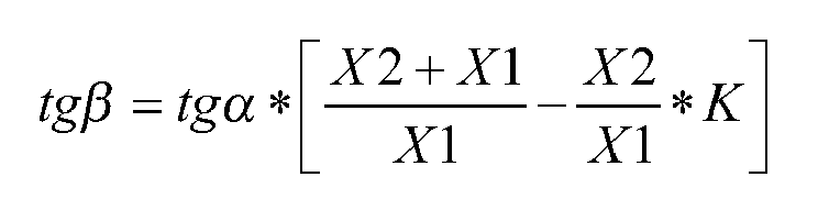
[0023] In particular, it was found that the optimum conditions in terms of reduction of
friction are obtained when the values of the trigonometric tangents of the two angles
α, β of contact are linked by the following relation:
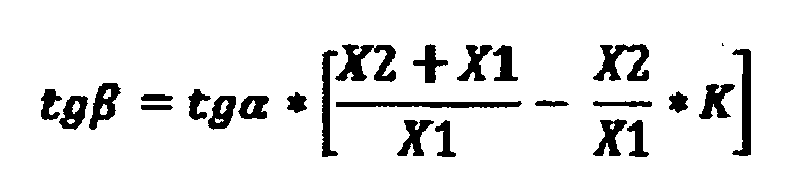
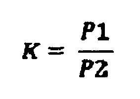
where:
[0024] With reference to figure 2, if the wheel hub assembly is symmetrical, i.e. with k
equal to 1, and if the angles α, β' of contact have the same magnitude, the forces
of reaction, indicated in this case by F1', F2' would be applied in respective centres
R1', R2' of reaction at axial distances X1', X2' respectively from the centre PR of
application.
[0025] Considering the load diagram of the symmetrical wheel hub assembly 10 (k=1), but
with different magnitudes of the angles α , β of contact, i.e. with the magnitude
of the angle β smaller than the magnitude of the angle α and smaller than the magnitude
of the angle β' and comparing it with the load diagram of a symmetrical wheel hub
assembly and with the same magnitudes of the angles α, β, of contact, the centre R2
of reaction of the force F2 of reaction is displaced to an axial distance X2 that
is smaller than the distance X2' with a consequent increase of the intensity of the
force F2 of reaction. However, the reduction of the magnitude of the angle β of contact
gives rise, at kinematic level, to a reduction of the revolution speed of the balls
13 around the axis A with a consequent reduction of the friction between balls 13
and raceways 112, 122.
[0026] When, on the other hand, the wheel hub assembly 10 is asymmetrical, i.e. k is greater
than one, and the angles α, β of contact have different magnitudes, the centre R1
of reaction of the force F1 of reaction will be displaced, as compared to the previous
case of a symmetrical wheel hub assembly, to an axial distance X1 greater than the
distance X1' with a consequent decrease of the intensity of the force F2 of reaction
and a better distribution of the forces F1, F2 of reaction without any substantial
variation of the speed of revolution of the balls 13 of the row C1 around the axis
A. Therefore, in an asymmetrical wheel hub assembly 10, as well as benefitting from
greater rigidity, there is also the benefit of better distribution of the forces,
thereby allowing the balls 13 of each row C1, C2 to work in better load conditions
and with less friction between the raceways and the balls 13 to the complete advantage
of consumption and pollutant emissions.
[0027] It is intended that the invention not be limited to the embodiments described and
illustrated here, which are to be considered as examples of the asymmetrical wheel
hub assembly which is, instead, open to further modifications as regards shapes and
arrangements of the parts, and constructional and assembly details.
1. An asymmetric wheel hub (10) (10') assembly having an axis (A) of rotation and comprises
two rows (C1, C2) of rolling bodies (13) with different pitch diameters (P1, P2) and,
for each row (C1)(C2) of rolling bodies (13), an inner raceway (111, 112) and an outer
raceway (121, 122), which are axially displaced in accordance with a respective angle
of contact and along a respective load line (L1, L2) in order to allow the assembly
to support combined loads, the raceways of each row (C1)(C2) of rolling bodies (13)
being provided with respective osculations which are defined by the ratio between
the radius of the raceways and the outer diameters of the rolling bodies (13) of the
associated row of rolling bodies (13), wherein the angle of contact and the osculation
of a first, outboard side row (C1) of rolling bodies (13) of the two rows (C1, C2)
of rolling bodies (13) are different from the angle of contact and, respectively,
the osculation of a second, inboard side row (C2) of rolling bodies (13) of the two
rows (C1, C2) of rolling bodies (13);
characterized in that the angle of contact of the first, outboard side row (C1) of rolling bodies (13)
has an magnitude which is greater than the magnitude of the second, inboard side row
(C2) of rolling bodies (13).
2. An asymmetric wheel hub assembly according to Claim 1, characterized in that the osculation of the outer raceway (121) of the first row (C1) of rolling bodies
(13) has a value which is greater than the value of the osculation of the outer raceway
(122) of the second row (C2) of rolling bodies (13).
3. An asymmetric wheel hub assembly according to Claim 2, characterized in that the osculation of the outer raceway (121) of the first row (C1) of rolling bodies
(13) is 1.004 times greater than the osculation of the outer raceway (122) of the
second row (C2) of rolling bodies (13).
4. An asymmetric wheel hub assembly according to Claim 1, 2 or 3, characterized in that the osculation of the inner raceway (111) of the first row (C1) of rolling bodies
(13) has a value which is greater than the value of the osculation of the inner raceway
(112) of the second row (C2) of rolling bodies (13).
5. An asymmetric wheel hub assembly according to Claim 4, characterized in that the osculation of the inner raceway (111) of the first row (C1) of rolling bodies
(13) is 1.004 times greater than the osculation of the inner raceway (112) of the
second row (C2) of rolling bodies (13).
6. An asymmetric wheel hub assembly according to Claim 3 or 5, characterized in that the outer diameters of the rolling bodies (13) of the first row (C1) of rolling bodies
(13) have sizes which are equal to the sizes of the outer diameters of the rolling
bodies (13) of the second row (C2) of rolling bodies (13).
7. An asymmetric wheel hub assembly according to Claim 3 or 5, characterized in that the outer diameters of the rolling bodies (13) of the first row (C1) of rolling bodies
(13) have sizes which are smaller than the sizes of the outer diameters of the rolling
bodies (13) of the second row (C2) of rolling bodies (13).
8. An asymmetric wheel hub assembly according to Claim 1,
characterized in that first row (C1) of rolling bodies (13) and the second row (C2) of rolling bodies (13)
react to a wheel load (FR), which is applied at a pressure centre (PR) located along
the axis (A) of rotation, with a first reaction force (F1) and a second reaction force
(F2) which are applied by a respective first reaction centre (R1) and by a respective
second reaction centre (R2), and that, having defined:
X1: an axial distance between the first reaction centre (R1) and the pressure centre
(PR);
X2: an axial distance between the second reaction 10 centre (R2) and the pressure
centre (PR);
P1: a pitch diameter of the first row (C1) of rolling bodies (13);
P2: a pitch diameter of the second row (C2) of rolling bodies (13);
α: a angle of contact of the first row (C1) of rolling bodies (13);
ß: a angle of contact of the second row (C2) of rolling bodies (13);
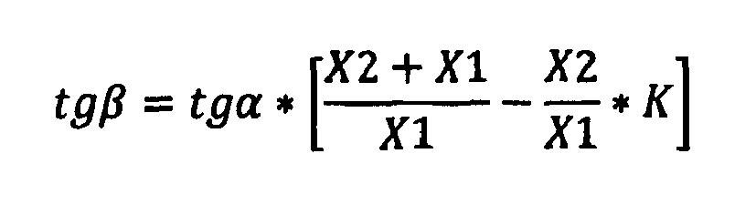
the values of the trigonometric tangent of the two angle of contacts α and ß are linked
by the following relationship:

where:
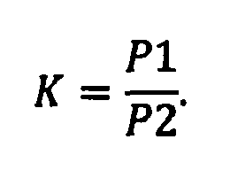
9. An asymmetric wheel hub assembly according to Claim 8, characterized in that the pitch diameter (P1) of the first row (C1) of rolling bodies (13) is greater than
the pitch diameter (P2) of the second row (C2) of rolling bodies (13).
10. An asymmetric wheel hub assembly according to Claim 9, characterized in that it also comprises an inner ring (11) and an outer ring (12) which are coaxial with
respect to one another and to the rotation axis (A) and which revolve with respect
to one another because of the interposition of the two rows (C1, C2) of rolling bodies
(13); the inner raceway (111, 112) and the outer raceway (121, 122) of each row (C1)(C2)
of rolling bodies (13) being obtained externally to the inner ring (11) and, respectively,
internally to the outer ring (12).
11. An asymmetric wheel hub assembly according to Claim 10, characterized in that the inner ring (11) is a flanged ring (11) and is provided with a flange (14) which
is transversal to the axis (A) of rotation for fitting a wheel.
12. An asymmetric wheel hub assembly according to Claim 11, characterized in that the inner raceway (111) of the first row (C1) of rolling bodies (13) is directly
obtained on the outside of the inner ring (11) and close to the flange (14).
13. An asymmetric wheel hub assembly according to Claim 12, characterized in that the inner ring (11) comprises a spindle (15), which extends along the axis (A) of
rotation and is made of the same material as the flange (14); the inner raceway (111)
of the first row (C1) of rolling bodies (13) being directly obtained on an outer surface
of the spindle (15).
14. An asymmetric wheel hub assembly according to Claim 13, characterized in that the inner ring (11) also comprises an applied inner ring (16) which is fitted on
the spindle (15); the inner raceway (112) of the second row (C2) of rolling bodies
(13) being directly obtained on the applied inner ring (16).
15. An asymmetric wheel hub assembly according to Claim 14, characterized in that the outer raceways of the first and of the second row (C2) of rolling bodies (13)
are directly obtained on an inner surface of the outer ring (12).
1. Asymmetrische Radnabengruppe (10)(10'), die eine Rotationsachse (A) hat und zwei Reihen
(C1, C2) von Wälzkörpern (13) mit unterschiedlichen Flankendurchmessern (P1, P2) umfasst
sowie für jede Reihe (C1) (C2) von Wälzkörpern (13) einen inneren Laufring (111, 112)
und einen äußeren Laufring (121, 122), die gemäß einem jeweiligen Kontaktwinkel und
entlang einer jeweiligen Lastlinie (L1, L2) axial verschoben sind, um der Baugruppe
zu ermöglichen, kombinierte Lasten abzustützen, wobei die Laufringe jeder Reihe (C1)
(C2) von Wälzkörpern (13) mit jeweiligen Schmiegungen versehen sind, welche durch
das Verhältnis zwischen dem Radius der Laufringe und den Außendurchmessern der Wälzkörper
(13) der zugehörigen Reihe von Wälzkörpern (13) definiert sind, wobei der Kontaktwinkel
und die Schmiegung einer ersten Außenseitenreihe (C1) von Wälzkörpern (13) der zwei
Reihen (C1, C2) von Wälzkörpern (13) sich vom Kontaktwinkel bzw. der Schmiegung einer
zweiten Innenseitenreihe (C2) von Wälzkörpern (13) der zwei Reihen (C1, C2) von Wälzkörpern
(13) unterscheiden;
dadurch gekennzeichnet, dass der Kontaktwinkel der ersten äußeren Reihe (C1) von Wälzkörpern (13) eine Größe hat,
die größer als die Größe der zweiten, inneren Reihe (C2) von Wälzkörpern (13) ist.
2. Asymmetrische Radnabengruppe nach Anspruch 1, dadurch gekennzeichnet, dass die Schmiegung des äußeren Laufrings (121) der ersten Reihe (C1) von Wälzkörpern
(13) einen Wert hat, der größer als der Wert der Schmiegung des äußeren Laufrings
(122) der zweiten Reihe (C2) von Wälzkörpern (13) ist.
3. Asymmetrische Radnabengruppe nach Anspruch 2, dadurch gekennzeichnet, dass die Schmiegung des äußeren Laufrings (121) der ersten Reihe (C1) von Wälzkörpern
(13) 1,004-mal größer als die Schmiegung des äußeren Laufrings (122) der zweiten Reihe
(C2) von Wälzkörpern (13) ist.
4. Asymmetrische Radnabengruppe nach Anspruch 1, 2 oder 3, dadurch gekennzeichnet, dass die Schmiegung des inneren Laufrings (111) der ersten Reihe (C1) von Wälzkörpern
(13) einen Wert hat, der größer als der Wert der Schmiegung des inneren Laufrings
(112) der zweiten Reihe (C2) von Wälzkörpern (13) ist.
5. Asymmetrische Radnabengruppe nach Anspruch 4, dadurch gekennzeichnet, dass die Schmiegung des inneren Laufrings (111) der ersten Reihe (C1) von Wälzkörpern
(13) 1,004-mal größer als die Schmiegung des inneren Laufrings (112) der zweiten Reihe
(C2) von Wälzkörpern (13) ist.
6. Asymmetrische Radnabengruppe nach Anspruch 3 oder 5, dadurch gekennzeichnet, dass die Außendurchmesser der Wälzkörper (13) der ersten Reihe (C1) von Wälzkörpern (13)
Größen haben, die gleich den Größen der Außendurchmesser (13) der zweiten Reihe (C2)
von Wälzkörpern (13) sind.
7. Asymmetrische Radnabengruppe nach Anspruch 3 oder 5, dadurch gekennzeichnet, dass die Außendurchmesser der Wälzkörper (13) der ersten Reihe (C1) von Wälzkörpern (13)
Größen haben, die kleiner als die Größen der Außendurchmesser (13) der zweiten Reihe
(C2) von Wälzkörpern (13) sind.
8. Asymmetrische Radnabengruppe nach Anspruch 1,
dadurch gekennzeichnet, dass die erste Reihe (C1) von Wälzkörpern (13) und die zweite Reihe (C2) von Wälzkörpern
(13) auf eine Radlast (FR) reagieren, die in einem Druckzentrum (PR) entlang der Rotationsachse
(A) aufgebracht wird, mit einer ersten Reaktionskraft (F1) und einer zweiten Reaktionskraft
(F2), die durch ein jeweiliges erstes Reaktionszentrum (R1) und ein jeweiliges zweites
Reaktionszentrum (R2) aufgebracht wird, dass sie Folgendes definiert:
X1: ein axialer Abstand zwischen dem ersten Reaktionszentrum (R1) und dem Druckzentrum
(PR);
X2: ein axialer Abstand zwischen dem zweiten Reaktionszentrum (R2) und dem Druckzentrum
(PR);
P1: ein Flankendurchmesser der ersten Reihe (C1) von Wälzkörpern (13);
P2: ein Flankendurchmesser der zweiten Reihe (C2) von Wälzkörpern (13);
α: ein Kontaktwinkel der ersten Reihe (C1) von Wälzkörpern (13);
β: ein Kontaktwinkel der zweiten Reihe (C2) von Wälzkörpern (13);
die Werte der trigonometrischen Tangente der zwei Kontaktwinkel α und β sind durch
die folgende Beziehung miteinander verbunden:
wobei:
9. Asymmetrische Radnabengruppe nach Anspruch 8, dadurch gekennzeichnet, dass der Flankendurchmesser (P1) der ersten Reihe (C1) von Wälzkörpern (13) größer als
der Flankendurchmesser (P2) der zweiten Reihe (C2) von Wälzkörpern (13) ist.
10. Asymmetrische Radnabengruppe nach Anspruch 9, dadurch gekennzeichnet, dass sie auch einen Innenring (11) und einen Außenring (12) umfasst, die koaxial zu einander
und zur Rotationsachse (A) sind und die sich wegen des Eingreifens der zwei Reihen
(C1, C2) von Wälzkörpern (13) gegeneinander drehen; wobei der innere Laufring (111,
112) und der äußere Laufring (121, 122) jeder Reihe (C1)(C2) von Wälzkörpern (13)
extern zum Innenring (11) bzw. intern zum Außenring (12) vorgesehen sind.
11. Asymmetrische Radnabengruppe nach Anspruch 10, dadurch gekennzeichnet, dass der Innenring (11) ein Flanschring (11) ist und mit einem Flansch (14) versehen ist,
der senkrecht zur Rotationsachse (A) zum Ansetzen eines Rades ist.
12. Asymmetrische Radnabengruppe nach Anspruch 11, dadurch gekennzeichnet, dass der innere Laufring (111) der ersten Reihe (C1) von Wälzkörpern (13) direkt auf der
Außenseite des Innenrings (11) und dicht beim Flansch (14) vorgesehen ist.
13. Asymmetrische Radnabengruppe nach Anspruch 12, dadurch gekennzeichnet, dass der Innenring (11) eine Spindel (15) umfasst, die sich entlang der Rotationsachse
(A) erstreckt und aus demselben Material wie der Flansch (14) hergestellt ist; wobei
der innere Laufring (111) der ersten Reihe (C1) von Wälzkörpern (13) direkt auf einer
Außenfläche der Spindel (15) vorgesehen ist.
14. Asymmetrische Radnabengruppe nach Anspruch 13, dadurch gekennzeichnet, dass der Innenring (11) auch einen aufgebrachten Innenring (16) umfasst, der auf der Spindel
(15) montiert ist; wobei der innere Laufring (112) der zweiten Reihe (C2) von Wälzkörpern
(13) direkt auf dem aufgebrachten Innenring (16) vorgesehen ist.
15. Asymmetrische Radnabengruppe nach Anspruch 14, dadurch gekennzeichnet, dass die äußeren Laufringe der ersten und der zweiten Reihe (C2) von Wälzkörpern (13)
direkt auf einer Innenfläche des Außenrings (12) vorgesehen ist.
1. Ensemble de moyeu de roue asymétrique (10) (10') ayant un axe de rotation (A) et comprenant
deux rangées (C1, C2) de corps de roulement (13) ayant des diamètres de pas différents
(P1, P2) et, pour chaque rangée (C1) (C2) de corps de roulement (13), un chemin de
roulement interne (111, 112) et un chemin de roulement externe (121, 122), qui sont
déplacés axialement suivant un angle de contact respectif et le long d'une ligne de
charge respective (L1, L2), afin de permettre à l'ensemble de supporter des charges
combinées, les chemins de roulement de chaque rangée (C1) (C2) de corps de roulement
(13) étant pourvus d'osculations respectives qui sont définies par le rapport entre
le rayon des chemins de roulement et les diamètres extérieurs des corps de roulement
(13) de la rangée associée de corps de roulement (13), l'angle de contact et l'osculation
d'une première rangée latérale extérieure (C1) de corps de roulement (13) des deux
rangées (C1, C2) de corps de roulement (13) étant différents de l'angle de contact
et, respectivement, de l'osculation d'une deuxième rangée latérale intérieure (C2)
de corps de roulement (13) des deux rangées (C1, C2) de corps de roulement (13) ;
caractérisé en ce que l'angle de contact de la première rangée latérale extérieure (C1) de corps de roulement
(13) présente une amplitude qui est supérieure à l'amplitude de la deuxième rangée
latérale intérieure (C2) de corps de roulement (13).
2. Ensemble de moyeu de roue asymétrique selon la revendication 1, caractérisé en ce que l'osculation du chemin de roulement externe (121) de la première rangée (C1) de corps
de roulement (13) a une valeur qui est supérieure à la valeur de l'osculation du chemin
de roulement externe (122) de la deuxième rangée (C2) de corps de roulement (13).
3. Ensemble de moyeu de roue asymétrique selon la revendication 2, caractérisé en ce que l'osculation du chemin de roulement externe (121) de la première rangée (C1) de corps
de roulement (13) est 1,004 fois supérieure à l'osculation du chemin de roulement
externe (122) de la deuxième rangée (C2) de corps de roulement (13).
4. Ensemble de moyeu de roue asymétrique selon la revendication 1, 2 ou 3, caractérisé en ce que l'osculation du chemin de roulement interne (111) de la première rangée (C1) de corps
de roulement (13) a une valeur qui est supérieure à la valeur de l'osculation du chemin
de roulement interne (112) de la deuxième rangée (C2) de corps de roulement (13).
5. Ensemble de moyeu de roue asymétrique selon la revendication 4, caractérisé en ce que l'osculation du chemin de roulement interne (111) de la première rangée (C1) de corps
de roulement (13) est 1,004 fois supérieure à l'osculation du chemin de roulement
interne (112) de la deuxième rangée (C2) de corps de roulement (13).
6. Ensemble de moyeu de roue asymétrique selon la revendication 3 ou 5, caractérisé en ce que les diamètres extérieurs des corps de roulement (13) de la première rangée (C1) de
corps de roulement (13) ont des dimensions qui sont égales aux dimensions des diamètres
extérieurs des corps de roulement (13) de la deuxième rangée (C2) de corps de roulement
(13).
7. Ensemble de moyeu de roue asymétrique selon la revendication 3 ou 5, caractérisé en ce que les diamètres extérieurs des corps de roulement (13) de la première rangée (C1) de
corps de roulement (13) ont des dimensions qui sont inférieures aux dimensions des
diamètres extérieurs des corps de roulement (13) de la deuxième rangée (C2) de corps
de roulement (13).
8. Ensemble de moyeu de roue asymétrique selon la revendication 1,
caractérisé en ce que la première rangée (C1) de corps de roulement (13) et la deuxième rangée (C2) de
corps de roulement (13) réagissent à une charge de roue (FR) qui est appliquée au
niveau d'un centre de pression (PR) situé le long de l'axe de rotation (A), avec une
première force de réaction (F1) et une deuxième force de réaction (F2) qui sont appliquées
par un premier centre de réaction respectif (R1) et par un deuxième centre de réaction
respectif (R2), et
en ce que, étant donné
X1 : une distance axiale entre le premier centre de réaction (R1) et le centre de
pression (PR) ;
X2 : une distance axiale entre le deuxième centre de réaction (R2) et le centre de
pression (PR) ;
P1 : un diamètre de pas de la première rangée (C1) de corps de roulement (13) ;
P2
: un diamètre de pas de la deuxième rangée (C2) de corps de roulement (13) ;
α : un angle de contact de la première rangée (C1) de corps de roulement (13) ;
β : un angle de contact de la deuxième rangée (C2) de corps de roulement (13) ;
les valeurs de la tangente trigonométrique des deux angles de contact α et β sont
liées par la relation suivante :
avec :
9. Ensemble de moyeu de roue asymétrique selon la revendication 8, caractérisé en ce que le diamètre de pas (P1) de la première rangée (C1) de corps de roulement (13) est
supérieur au diamètre de pas (P2) de la deuxième rangée (C2) de corps de roulement
(13).
10. Ensemble de moyeu de roue asymétrique selon la revendication 9, caractérisé en ce qu'il comprend également une bague interne (11) et une bague externe (12) qui sont coaxiales
l'une par rapport à l'autre et à l'axe de rotation (A) et qui tournent l'une par rapport
à l'autre du fait de l'interposition des deux rangées (C1, C2) de corps de roulement
(13) ; le chemin de roulement interne (111, 112) et le chemin de roulement externe
(121, 122) de chaque rangée (C1) (C2) de corps de roulement (13) étant obtenus à l'extérieur
de la bague interne (11) et respectivement, à l'intérieur de la bague externe (12).
11. Ensemble de moyeu de roue asymétrique selon la revendication 10, caractérisé en ce que la bague interne (11) est une bague bridée (11) et est pourvue d'une bride (14) qui
est transversale à l'axe de rotation (A) pour l'ajustement d'une roue.
12. Ensemble de moyeu de roue asymétrique selon la revendication 11, caractérisé en ce que le chemin de roulement interne (111) de la première rangée (C1) de corps de roulement
(13) est directement obtenu sur l'extérieur de la bague interne (11) et à proximité
de la bride (14).
13. Ensemble de moyeu de roue asymétrique selon la revendication 12, caractérisé en ce que la bague interne (11) comprend une broche (15) qui s'étend le long de l'axe de rotation
(A) et qui est fabriquée en le même matériau que la bride (14) ; le chemin de roulement
interne (111) de la première rangée (C1) de corps de roulement (13) étant directement
obtenu sur une surface extérieure de la broche (15).
14. Ensemble de moyeu de roue asymétrique selon la revendication 13, caractérisé en ce que la bague interne (11) comprend également une bague interne appliquée (16) qui est
ajustée sur la broche (15) ; le chemin de roulement interne (112) de la deuxième rangée
(C2) de corps de roulement (13) étant directement obtenu sur la bague interne appliquée
(16).
15. Ensemble de moyeu de roue asymétrique selon la revendication 14, caractérisé en ce que les chemins de roulement externes des première (C1) et deuxième (C2) rangées de corps
de roulement (13) sont directement obtenus sur une surface intérieure de la bague
externe (12).
REFERENCES CITED IN THE DESCRIPTION
This list of references cited by the applicant is for the reader's convenience only.
It does not form part of the European patent document. Even though great care has
been taken in compiling the references, errors or omissions cannot be excluded and
the EPO disclaims all liability in this regard.
Patent documents cited in the description