| (19) |
 |
|
(11) |
EP 2 055 435 B1 |
| (12) |
EUROPEAN PATENT SPECIFICATION |
| (45) |
Mention of the grant of the patent: |
|
10.12.2014 Bulletin 2014/50 |
| (22) |
Date of filing: 29.09.2008 |
|
| (51) |
International Patent Classification (IPC):
|
|
| (54) |
Fluid-operated torque wrench for and method of tightening or loosening fasteners
Fluid-betriebener Drehmomentschlüssel und Verfahren zum Festziehen oder Lockern von
Befestigungsmitteln
Clé dynamométrique hydraulique et procédé pour serrer ou desserrer des fixations
|
| (84) |
Designated Contracting States: |
|
DK NL NO SE |
| (30) |
Priority: |
29.10.2007 US 926285
|
| (43) |
Date of publication of application: |
|
06.05.2009 Bulletin 2009/19 |
| (73) |
Proprietor: Junkers, John K. |
|
Saddle River, NJ 07458 (US) |
|
| (72) |
Inventor: |
|
- Junkers, John K.
Saddle River, NJ 07458 (US)
|
| (74) |
Representative: Zacco Sweden AB |
|
P.O. Box 5581
114 85 Stockholm
114 85 Stockholm (SE) |
| (56) |
References cited: :
US-A- 2 972 918
US-A- 4 432 256
US-A- 4 706 527
US-A1- 2004 200 320
|
US-A- 4 106 371
US-A- 4 480 510
US-A- 5 301 574
|
|
| |
|
|
|
|
| |
|
| Note: Within nine months from the publication of the mention of the grant of the European
patent, any person may give notice to the European Patent Office of opposition to
the European patent
granted. Notice of opposition shall be filed in a written reasoned statement. It shall
not be deemed to
have been filed until the opposition fee has been paid. (Art. 99(1) European Patent
Convention).
|
BACKGROUND OF THE INVENTION
[0001] The present invention relates to a fluid-operated torque wrench for and a method
of tightening and loosening fasteners.
[0002] Power-driven torque tools require the use of reaction members. Reaction members usually
abut against a stationary object, such as for example an adjacent nut, to stop the
tool housing from turning backwards, while a fastener, such as for example a nut,
turns forwards. The abutment force for the tool with a torque 13,558 Nm (10,000 ft.lb)
can be as high as 133,447 N (30,000 lb), which is applied as a side load to the adjacent
nut in one direction and to the nut to be turned in the opposite direction. This enormous
abutment force tries to bend the bolt and to increase the turning friction of the
nut. On regular applications this is not a problem because the bolt is designed to
take the side loads, and the torque recommendations by manufacturers of equipment
usually take the side load into consideration.
[0003] The problem occurs during tightening up of critical applications when a scatter of
a bolt load applied to all fasteners on a flange or a casing can not vary too much,
or when loosening of corroded fasteners. The corrosion of a corroded fastener usually
occurs between the engaging threads of the nut and the bolt. On hot applications,
grease applied for assembly usually dries up and binds the threads together. When
a high torque with a high side load is applied to such a nut, then merely a half of
the threads between the bolt and the nut are engaged on one side and the threads on
the engaged side start gripping. This causes the bolt thread to gall and requires
more torque and thus more side load to take the nut off, which can totally ruin the
bolt and the nut threads. Hot applications are usually critical. Since most of the
bolts used on hot applications like turbines and casings are either stainless or precision
manufactured, the replacement costs are extremely high.
[0004] The galling also occurs not just between the threads of the bolt and the nut, but
also between the face of the nut and the face of the flange in which the fastener
is introduced, since the side load changes a perpendicular position of the nut to
be turned. This in turn increases the turning friction of the nut and makes the bolt
load generated by the torque unpredictable which can result in leaks or joint failures.
[0005] U.S. patent 4,706,527 discloses a fluid operated wrench for tightening or loosening a fastener and comprises;
a housing having two housing portions including a cylinder portion and a driving portion;
cylinder piston means; a ratchet mechanism, connected to said cylinder-piston means;
a second connecting means provided on the driving portion of the housing; a third
connecting means, which through a socket connects the wrench with the fastener to
be tightened or loosened; a second reaction arm element attached to the second connecting
means for abutting against a first stationary object.
[0006] Some other tools provided with reaction members are disclosed, for example, in
U.S. patent nos. 3,361,218,
4,549,438,
4,538,484,
4,607,546,
4,619,160,
4,671,142,
4,706,526,
4,928,558, 5,027,932,
5,016,502,
5,142,951,
5,152,200,
5,301,574,
5,791,619,
6,260,443, and
6,715,381.
SUMMARY OF THE INVENTION
[0007] Accordingly, it is an object of the present invention to provide a fluid-operated
torque wrench for and method of tightening and loosening fasteners, which are further
improvements of the existing wrenches for and methods of tightening or loosening fasteners.
[0008] In keeping with these objects and with others which will become apparent hereinafter,
one feature of the present invention resides, briefly stated, in a fluid-operated
torque wrench for tightening or loosening a fastener, comprising a housing having
two housing portions including a cylinder portion and a driving portion; cylinder-piston
means arranged in said cylinder portion and movable along a first axis, a ratchet
mechanism arranged in said driving portion and connected to said cylinder-piston means
to be driven by the later, said ratchet mechanism having a ratchet turnable about
a second axis which is perpendicular to said first axis; at least three connecting
means including first and second connecting means receiving a given turning force
acting in one direction during operation of the wrench, and a third connecting means
receiving a given turning force in another opposite direction during operation of
the wrench and being equal to said given turning force acting in said one direction,
so that one of said turning forces turns a fastener to be tightened or loosened while
another of said turning forces is transferred to a stationary object.
[0009] Another feature of the present invention resides, briefly stated, in a method of
tightening or loosening a fastener, comprising the steps of providing a housing having
two housing portions including a cylinder portion and a driving portion; arranging
cylinder-piston means in said cylinder portion and moving along a first axis; arranging
a ratchet mechanism in said driving portion and connecting to said cylinder-piston
means to be driven by the later; providing in said ratchet mechanism a ratchet turnable
about a second axis which is perpendicular to said first axis; providing at least
three connecting means including first, second and third connecting means; receiving
by said first and second connecting means a given turning force acting in one direction
during operation of the wrench; and receiving by said third connecting means a given
turning force in another opposite direction during operation of the wrench and being
equal to said given turning force acting in said one direction, so that one of said
turning forces turns a fastener to be tightened or loosened while another of said
turning forces is transferred to a stationary object.
[0010] When the fluid operated torque wrench for tightening or loosening fasteners is designed
and the method of tightening or loosening of fasteners is performed in accordance
with the present invention, the wrench can be applied as any torque wrench on regular
applications, which represent the majority and since it is simpler to use one reaction
arm on one of the first and second connecting means.
[0011] For critical applications, it is important to apply as little side load as possible
to reduce a frictional scatter, to avoid a galling of bolt thread and nut face, and
to improve an overall torque accuracy. This can be achieved by using two connecting
means, for two reaction members on the housing of the wrench, in particular the first
and the second connecting means, including one of the first and second connecting
means provided on a usual location around the cylinder portion of the housing and
another of the first and second connecting means provided, for example, on the driving
portion of the housing. By placing one reaction arm on each of the first and second
connecting means, the reaction members can abut against two stationary objects on
opposite sides of the axis of the third connecting means that connects the wrench
with the fastener, such as the nut to be tightened or loosened.
[0012] When the axis of the third connecting means which connects the tool with the nut
is located in a center, one abutment area for one reaction arm is located at the left
side of the center and another abutment area for another reaction arm is located at
the right side of the center, and the reaction arm that abuts to the right of the
center pushes its abutment area backwards from the center, while the reaction arm
that abuts at the left side of the center pushes its abutment area forwards from the
center. Since action and reaction are equal but opposite, the connecting means for
the reaction arm that abuts to the right of the center pushes the driving portion
of the housing forwards from the center, while the reaction arm that abuts to the
left of the center pushes the driving portion of the housing backward from the center.
Since both reaction arms apply an equal force, the usual side loads apply to the driving
portion of the wrench balance each other out. It is to be understood that if the wrench
is used with only one reaction arm, the usual side loads will be acting.
[0013] The advantage of the inventive tool also resides in its universality. With two connecting
means (first and second), users who dislike changes and constitute 95% of all users
will be willing to use the inventive tool because it allows them to apply the reaction
arm the way they are used to. At the same time, when this does not work for them,
they will have a possibility to apply extensions, to interconnect two wrenches with
one another, to eliminate the reaction arm and to reduce the usual side loads with
the use of two reaction arms that balance out the side loads.
[0014] The novel features which are considered as characteristic for the present invention
are set forth in particular in the appended claims. The invention itself, however,
both as to its construction and its method of operation, together with additional
objects and advantages thereof, will be best understood from the following description
of specific embodiments when read in connection with the accompanying drawings.
BRIEF DESCRIPTION OF THE DRAWINGS
[0015]
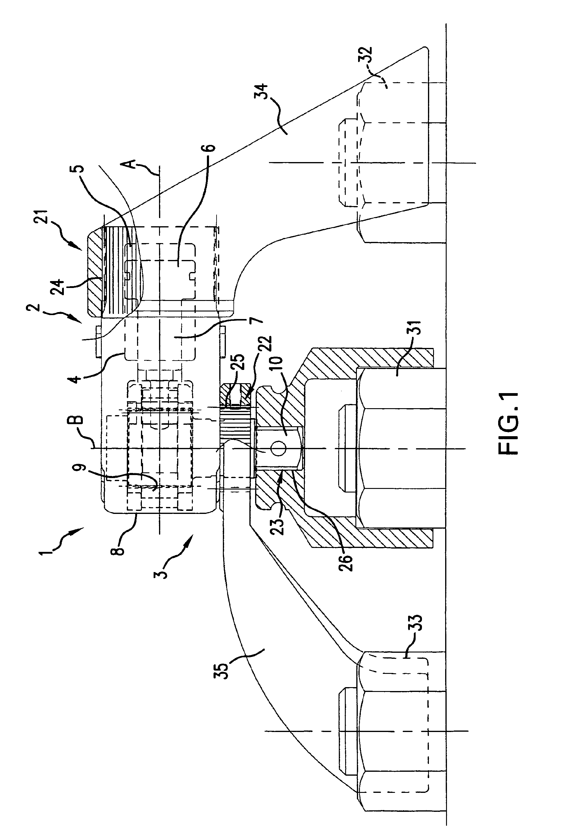
Figure 1 is a side view of a fluid-operated torque wrench for tightening or loosening
a fastener in accordance with the present invention; and
Figure 2 is a plan view of the inventive fluid-operated torque wrench for tightening
or loosening a fastener.
DESCRIPTION OF THE PREFERRED EMBODIMENTS
[0016] A fluid-operated torque wrench in accordance with the present invention has a housing
which is identified as a whole with reference numeral 1. The housing has two housing
portions, including a cylinder portion 2 and a driving portion 3.
[0017] Cylinder-piston means 4 are arranged in the cylinder portion 2 and include a cylinder
which is identified with reference numeral 5, a piston reciprocatingly movable in
the cylinder along an axis A and identified with reference numeral 6, and a piston
rod 7 connected with the piston 6. The driving portion 3 of the housing accommodates
a known lever-type ratchet mechanism which is identified as a whole with reference
numeral 8 and includes a ratchet 9 which is turnable in the driving portion 3 of the
housing about an axis B that is perpendicular to the first axis A, as well known.
The ratchet 9 is connected with a driving element 10 for joint rotation therewith.
[0018] In accordance with the present invention, the fluid-operated torque wrench is provided
with at least three connecting means. The connecting means include first connecting
means which are identified with reference numeral 21, second connecting means which
are identified with reference numeral 22, and third connecting means which are identified
with reference numeral 23.
[0019] The first connecting means are configured for example as a polygonal formation 24
which is formed, for example, on a part of the cylinder portion 2 of the housing 1
and configured, for example, as a plurality of outer splines.
[0020] The second connecting means are formed, for example, as a polygonal formation 25
formed, for example, on a projection of the driving portion 3 of the housing 1 and
configured, for example, as a polygonal formation formed, for example, by a plurality
of outer splines.
[0021] The third connecting means 23 includes a polygonal formation 26 provided on the driving
element 11 and configured, for example, as a polygonal outer surface, such as a square
outer surface.
[0022] The first connecting means 21, the second connecting means 22, and the third connecting
means 23 are configured so that during operation of the wrench the first connecting
means 21 and the second connecting means 22 receive a given turning force acting in
one direction, while the third connecting means 23 receive a turning force in an opposite
direction as shown by arrows in Figure 2 of the drawings.
[0023] When the ratchet 9 turns in the driving portion 3 of the housing 1 in the other direction
and drives the driving element 10 to tighten or loosen a nut 31, the first connecting
means 21 transfers a given turning force to a stationary object which is, for example,
a neighboring nut 32 and the second connecting means 23 transfers a given turning
force to another stationary object which is, for example, a neighboring nut 33 in
the one direction which is opposite to the other direction.
[0024] In another mode of operation the first connecting means 21 and the second connecting
means 22 can receive a given turning force in one direction to turn the fasteners,
such as the nuts 32 and 33, while the ratchet 9 of the lever-type ratchet mechanism
in the driving portion 3 of the housing 1 applies another turning force which is equal
to the above mentioned given turning force acting in one direction, to the stationary
object which in this case is the nut 31, in another direction which is opposite to
the one direction.
[0025] It can be seen that the given turning force of the first connecting means 21 and
the second connecting means 22 acting in one direction can be transferred by one of
the first connecting means 21 and the second connecting means 22 to the stationary
object 32 or 33, or the given turning force of the first connecting means 21 and the
second connecting means 22 acting in one direction can be transferred by said first
connecting means 21 and the second connecting means 22 for turning a fastener, in
particular the nut 32 and 33.
[0026] The first connecting means 21 and the second connecting means 22 can be both used
for transferring the given turning force by the first connecting means 21 and the
second connecting means 22 to the stationary objects represented by the nuts 32 and
33 or for turning the nut 32 and 33. At the same time it is possible to use only one
of the first and second connecting means 21 and 22 for transferring the given turning
force to one of the stationary objects represented by one of the nuts 32 or 33 or
to turn one of the nuts 32 or 33, depending on applications of the fluid-operated
torque wrench.
[0027] In accordance with the present invention, while the first connecting means 21 is
arranged on the usual location around the cylinder portion of the . housing 1, the
second connecting means 22 is arranged around the drive or the driving element on
the driving portion 3 of the housing 1. By connecting reaction arms 34 and 35 to the
first connecting means 21 and the second connecting means 22 and placing the reaction
arms 34 and 35 against two stationary objects 32 and 33 on opposite sides of the axis
of the connecting means 23 to the nut 31 to be tightened or loosened, the nut 31 to
be tightened or loosened is located in the center, one abutment area for the reaction
arm 35 is arranged at the left side of the center and the other reaction arm 34 is
arranged at the right side of the center, so that the reaction arm 34 that abuts at
the right of the center pushes its abutment area backwards from the center, while
the reaction arm 35 that abuts at the left side of the center pushes its abutment
area forwards from the center.
[0028] Since action and reaction are equal but opposite, the connecting means 21 for the
reaction arm 34 that abuts at the right of the center pushes the driving portion of
the housing forwards from the center, while the reaction arm 35 that abuts at the
left of the center pushes the driving portion backwards. Since both apply an equal
force, the usual side loads applied to the driving portion of the wrench balance each
other out when both reaction arms 34 and 35 are used. Of course, the wrench can be
used with only one of the reaction arms 34 or 35, as explained above.
[0029] It will be understood that each of the elements described above, or two or more together,
may also find a useful application in other types of constructions differing from
the type described above.
[0030] While the invention has been illustrated and described as embodied in a fluid-operated
torque wrench for and a method for tightening and loosening fasteners, it is not intended
to be limited to the details shown, since various modifications and structural changes
may be made without departing in any way from the basic idea of the invention as being
defined in the appended claims.
1. A fluid-operated torque wrench for tightening or loosening a fastener, comprising:
a housing (1) having two housing portions (2, 3) including a cylinder portion (2)
and a driving portion (3); cylinder-piston means (5, 6) arranged in said cylinder
portion (2) and movable along a first axis (A); a ratchet mechanism (8) arranged in
said driving portion (3) and connected to said cylinder-piston means (5, 6) to be
driven by the later, said ratchet mechanism (8) having a ratchet (9) which drives
a driving element (10) and which is turnable about a second axis (B) that is perpendicular
to said first axis (A); further comprising at least three connecting means (21, 22,
23) including first connecting means (21) for receiving a given turning force acting
in one direction during operation of the wrench, a second connecting means (22) receiving
a given turning force acting in one direction during operation of the wrench, and
a third connecting means (23) receiving a given turning force in another opposite
direction during operation of the wrench and being equal to said given turning force
acting in said one direction, so that one of said turning forces turns a fastener
(31) to be tightened or loosened while another of said turning forces is transferred
to a stationary object (32, 33), wherein one of said first and second connecting means
(21, 22) is provided on said cylinder portion (2) of said housing (1), the other of
said first and second connecting means (21, 22) is provided on said driving portion
(3) of said housing (1), and said third connecting means (23) includes a polygonal
formation (26) provided on said driving element (10) and connects the wrench with
the fastener (31); a first reaction arm element (34) attached to said first connecting
means (21) for abutting against a first stationary object (32) and a second reaction
arm element (35) attached to said second connecting means (22) for abutting against
a second stationary object (33), wherein the two stationary objects (32, 33) are on
opposite sides of the axis of said third connecting means (23).
2. A fluid-operated torque wrench as defined in claim 1, wherein said connecting means
(21, 22, 23) are configured so that said ratchet (9) turns in said driving portion
(3) to tighten or loosen a nut (31) in the other direction which is opposite to said
one direction in which said first and second connecting means (21, 22) transfer a
given turning force to the stationary object (32, 33).
3. A fluid-operated torque wrench as defined in claim 1, wherein said first and second
connecting means (21, 22) are provided on said housing (1), so that said first and
second reaction arm elements (33, 35) are connected with said housing (1) through
said first and second connecting means (21, 22).
4. A method of tightening or loosening a fastener, comprising the steps of: providing
a fluid-operated torque wrench for tightening or loosening a fastener comprising a
housing (1) having two housing portions (2, 3) including a cylinder portion (2) and
a driving portion (3); arranging cylinder-piston means (5, 6) in said cylinder portion
(2) and movable along a first axis (A); arranging a ratchet mechanism (8) in said
driving portion (3) and connecting it to said cylinder-piston means (5, 6) to be driven
by the latter, said ratchet mechanism (8) having a ratchet (9) which drives a driving
element (10) and which is turnable about a second axis (B) that is perpendicular to
said first axis (A); providing at least three connecting means (21, 22, 23) including
a first connecting means (21) for receiving a given turning force acting in one direction
during operation of the wrench, a second connecting means (22) receiving a given turning
force acting in one direction during operation of the wrench, and a third connecting
means (23) receiving a given turning force in another opposite direction during operation
of the wrench and being equal to said given turning force acting in said one direction,
so that one of said turning forces turns a fastener (31) to be tightened or loosened
while another of said turning forces is transferred to a stationary object (32, 33);
arranging one of said first and second connecting means (21, 22) on said cylinder
portion (2) of said housing (1), the other of said first and second connecting means
(21, 22) on said driving portion (3) of said housing (1), and said third connecting
means (23) including a polygonal formation (26) on said driving element (10); attaching
a first reaction arm element (34) to said first connecting means (21) for abutting
against a first stationary object (32) and attaching a second reaction arm element
(35) to said second connecting means (22) for abutting against a second stationary
object (33), wherein the two stationary objects (32, 33) are on opposite sides of
the axis of said third connecting means (23); and connecting the wrench with the fastener
(31) by said third connecting means (23).
5. A method as defined in claim 4, further comprising turning said ratchet (9) in said
driving portion (3) by means of said cylinder-piston means (5, 6) driving said ratchet
mechanism (8) to tighten or loosen a nut (31) in the other direction which is opposite
to said one direction in which said first and second connecting means (21, 22) transfer
a given turning force to the stationary object (32, 33).
6. A method as defined in claim 4, further comprising providing said first and second
connecting means (21, 22) on said housing (1), and connecting said first and second
reaction arm elements (33, 35) with said housing (1) through said first and second
connecting means (21, 22).
1. Fluid-betriebener Drehmomentschlüssel zum Festziehen oder Lockern eines Befestigungsmittels,
umfassend: ein Gehäuse (1) mit zwei Gehäuseteilen (2, 3) umfassend einen Zylinderteil
(2) und einen Antriebsteil (3); Zylinderkolbenmittel (5, 6), welche in dem Zylinderteil
(2) angeordnet sind und entlang einer ersten Achse (A) beweglich sind; einen Ratschenmechanismus
(8), welcher in dem Antriebsteil (3) angeordnet und mit den Zylinderkolbenmitteln
(5, 6) verbunden ist, um von dem letzteren angetrieben zu werden, wobei der Ratschenmechanismus
(8) eine Ratsche (9) aufweist, welche ein Antriebselement (10) antreibt und um eine
zur ersten Achse (A) senkrechte zweite Achse (B) drehbar ist; ferner umfassend zumindest
drei Verbindungsmittel (21, 22, 23) umfassend ein erstes Verbindungsmittel (21) zur
Aufnahme einer gegebenen Drehkraft, die während des Betreibens des Schlüssels in eine
Richtung ausgeübt wird, ein zweites Verbindungsmittel (22), welches eine gegebene
Drehkraft aufnimmt, die während des Betreibens des Schlüssels in eine Richtung ausgeübt
wird, und ein drittes Verbindungsmittel (23), welches während des Betreibens des Schlüssels
eine gegebene Drehkraft in eine andere, entgegengesetzte Richtung aufnimmt, welche
der in die eine Richtung ausgeübten Drehkraft entspricht, so dass eine der gegebenen
Drehkräfte ein festzuziehendes oder zu lockerndes Befestigungsmittel (31) dreht, während
eine andere der Drehkräfte auf einen ortsfesten Gegenstand (32, 33) übertragen wird,
wobei eines des ersten und zweiten Verbindungsmittels (21, 22) an dem Zylinderteil
(2) des Gehäuses (1) vorgesehen ist, das andere des ersten und zweiten Verbindungsmittels
(21, 22) an dem Antriebsteil (3) des Gehäuses (1) vorgesehen ist, und das dritte Verbindungsmittel
(23) eine an dem Antriebsteil (10) vorgesehene polygonale Ausbildung (26) umfasst
und den Schlüssel mit dem Befestigungsmittel (31) verbindet; ein an dem ersten Verbindungsmittel
(21) befestigtes erstes Reaktionsarmelement (34) zur Anlage an einem ersten ortsfesten
Gegenstand (32) und ein mit dem zweiten Verbindungsmittel (22) befestigtes zweites
Reaktionsarmelement (35) zur Anlage an einem zweiten ortsfesten Gegenstand (33), wobei
die beiden ortsfesten Gegenstände (32, 33) an entgegengesetzten Seiten der Achse des
dritten Verbindungsmittels (23) angeordnet sind.
2. Fluid-betriebener Drehmomentschlüssel nach Anspruch 1, wobei die Verbindungsmittel
(21, 22, 23) derart ausgebildet sind, dass die Ratsche (9) in dem Antriebsteil (3)
dreht, um eine Nut (31) in die andere Richtung festzuziehen oder zu lockern, welche
der Richtung, in welcher das erste und das zweite Verbindungsmittel (21, 22) eine
gegebene Drehkraft auf den ortsfesten Gegenstand (32, 33) übertragen, entgegengesetzt
ist.
3. Fluid-betriebener Drehmomentschlüssel nach Anspruch 1, wobei das erste und das zweite
Verbindungsmittel (21, 22) an dem Gehäuse (1) derart vorgesehen sind, dass das erste
und das zweite Reaktionsarmelement (33, 35) über das erste und das zweite Verbindungsmittel
(21, 22) mit dem Gehäuse (1) verbunden ist.
4. Verfahren zum Festziehen oder Lockern eines Befestigungsmittels, umfassend die folgenden
Schritte: Vorsehen eines Fluid-betriebenen Drehmomentschlüssels zum Festziehen oder
Lockern eines Befestigungsmittels umfassend ein Gehäuse (1) mit zwei Gehäuseteilen
(2, 3) umfassend einen Zylinderteil (2) und einen Antriebsteil (3); Anordnen von Zylinderkolbenmitteln
(5, 6) in dem Zylinderteil (2), welche entlang einer ersten Achse (A) beweglich sind;
Anordnen eines Ratschenmechanismus (8) in dem Antriebsteil (3) und Verbinden von diesem
mit den Zylinderkolbenmitteln (5, 6), um von dem letzteren angetrieben zu werden,
wobei der Ratschenmechanismus (8) eine Ratsche (9) aufweist, welche ein Antriebselement
(10) antreibt und um eine zur ersten Achse (A) senkrechte zweite Achse (B) drehbar
ist; Vorsehen von zumindest drei Verbindungsmitteln (21, 22, 23) umfassend ein erstes
Verbindungsmittel (21) zur Aufnahme einer gegebenen Drehkraft, die während des Betreibens
des Schlüssels in eine Richtung ausgeübt wird, ein zweites Verbindungsmittel (22),
welches eine gegebene Drehkraft aufnimmt, die während des Betreibens des Schlüssels
in eine Richtung ausgeübt wird, und ein drittes Verbindungsmittel (23), welches während
des Betreibens des Schlüssels eine gegebene Drehkraft in eine andere, entgegengesetzte
Richtung aufnimmt, welche der in die eine Richtung ausgeübten Drehkraft entspricht,
so dass eine der gegebenen Drehkräfte ein festzuziehendes oder zu lockerndes Befestigungsmittel
(31) dreht, während eine andere der Drehkräfte auf einen ortsfesten Gegenstand (32,
33) übertragen wird; Anordnen eines des ersten und zweiten Verbindungsmittels (21,
22) an dem Zylinderteil (2) des Gehäuses (1), des anderen des ersten und zweiten Verbindungsmittels
(21, 22) an dem Antriebselement (3) des Gehäuses (1), wobei das dritte Verbindungsmittel
(23) eine polygonale Ausbildung (26) an dem Antriebsteil (10) umfasst; Befestigen
eines ersten Reaktionsarmelements (34) an dem ersten Verbindungsmittel (21) zur Anlage
an einem ersten ortsfesten Gegenstand (32) und Befestigen eines zweiten Reaktionsarmelements
(35) an dem zweiten Verbindungsmittel (22) zur Anlage an einem zweiten ortsfesten
Gegenstand (33), wobei die beiden ortsfesten Gegenstände (32, 33) an entgegengesetzten
Seiten der Achse des dritten Verbindungsmittels (23) angeordnet sind; und Verbinden
des Schlüssels mit dem Befestigungsmittel (31) über das dritte Verbindungsmittel (23).
5. Verfahren nach Anspruch 4, welches ferner ein Drehen der Ratsche (9) in dem Antriebsteil
(3) mittels der Zylinderkolbenmittel (5, 6), wodurch der Ratschenmechanismus (8) dazu
angetrieben wird, eine Nut (31) in die andere Richtung festzuziehen oder zu lockern,
welche Richtung der einen Richtung, in welcher das erste und das zweite Verbindungsmittel
(21, 22) eine gegebene Drehkraft auf den ortsfesten Gegenstand (32, 33) übertragen,
entgegengesetzt ist, umfasst.
6. Verfahren nach Anspruch 4, welches ferner ein Vorsehen des ersten und des zweiten
Verbindungsmittels (21, 22) an dem Gehäuse (1) und ein Verbinden des ersten und des
zweiten Reaktionsarmelements (33, 35) mit dem Gehäuse (1) über das erste und das zweite
Verbindungsmittel (21, 22) umfasst.
1. Clé dynamométrique hydraulique pour serrer ou desserrer un élément de fixation, comprenant
un boîtier (1) comportant deux parties de boîtier (2, 3) comprenant une partie de
cylindre (2) et une partie d'entraînement (3); des moyens de cylindre-piston (5, 6)
disposés dans ladite partie de cylindre (2) et pouvant se déplacer le long d'un premier
axe (A); un mécanisme à rochet (8) disposé dans ladite partie d'entraînement (3) et
relié auxdits moyens de cylindre-piston (5, 6) pour être entraînés par ceux-ci, ledit
mécanisme à rochet (8) présentant un rochet (9) entraînant un élément d'entraînement
(10) et pouvant pivoter autour d'un deuxième axe (B) qui est perpendiculaire audit
premier axe (A); comprenant en outre au moins trois moyens de raccord (21, 22, 23)
comprenant un premier moyen (21) pour la réception d'une force de rotation donnée
agissant dans une direction pendant le fonctionnement de la clé dynamométrique, un
deuxième moyen de raccord (22) recevant une force de rotation donnée agissant dans
une direction pendant le fonctionnement de la clé dynamométrique, et un troisième
moyen de raccord (23) recevant une force de rotation donnée dans une autre direction
opposée pendant le fonctionnement de la clé dynamométrique et étant égale à ladite
force de rotation donnée agissant dans ladite une direction, si bien que l'une desdites
forces de rotation tourne un élément de fixation (31) à être serré ou desserré tandis
qu'une autre desdites forces de rotation est transférée à un objet stationnaire (32,
33), l'un desdits premier et deuxième moyens de raccord (21, 22) étant pourvu sur
ladite partie de cylindre (2) dudit boîtier (1), l'autre desdits premier et deuxième
moyens de raccord (21, 22) étant pourvu sur ladite partie d'entraînement (3) dudit
boîtier (1), et le troisième moyen de raccord (23) comprenant une formation polygonale
(26) pourvue sur ledit élément d'entraînement (10) et reliant la clé dynamométrique
à l'élément de fixation (31); un premier élément de bras de réaction (34) attaché
audit premier moyen de raccord (21) pour venir en butée contre un premier objet stationnaire
(32) et un deuxième élément de bras de réaction (35) attaché audit deuxième moyen
de raccord (22) pour venir en butée contre un premier objet stationnaire (33), les
deux objets stationnaires (32, 33) étant pourvus sur des côtés opposés de l'axe dudit
troisième moyen de raccord (23).
2. Clé dynamométrique hydraulique selon la revendication 1, dans lequel lesdits moyens
de raccords (21, 22, 23) sont configurés si bien que ledit rochet (9) tourne dans
ladite partie d'entraînement (3) pour serrer ou desserrer un écrou (31) dans l'autre
direction qui est opposée à ladite une direction dans laquelle lesdits premier et
deuxième moyens de raccord (21, 22) transfèrent une force de rotation donnée à l'objet
stationnaire (32, 33).
3. Clé dynamométrique hydraulique selon la revendication 1, dans lequel lesdits premier
et deuxième moyens de raccord (21, 22) sont pourvus sur ledit boîtier (1), si bien
que lesdits premier et deuxième éléments de bras de réaction (33, 35) sont reliés
audit boîtier (1) à travers lesdits premier et deuxième moyens de raccord (21, 22).
4. Procédé pour serrer ou desserrer un élément de fixation, comprenant les étapes consistant
à fournir une clé dynamométrique hydraulique pour serrer ou desserrer un élément de
fixation comprenant un boîtier (1) comportant deux parties de boîtier (2, 3) comprenant
une partie de cylindre (2) et une partie d'entraînement (3); disposer des moyens de
cylindre-piston (5, 6) dans ladite partie de cylindre (2) et pouvant se déplacer le
long d'un premier axe (A); disposer un mécanisme à rochet (8) dans ladite partie d'entraînement
(3) et le relier auxdits moyens de cylindre-piston (5, 6) pour être entraîné par ceux-ci,
ledit mécanisme à rochet (8) ayant un rochet (9) entraînant un élément d'entraînement
(10) et pouvant pivoter autour d'un deuxième axe (B) qui est perpendiculaire audit
premier axe (A); fournir au moins trois moyens de raccord (21, 22, 23) comprenant
un premier moyen de raccord (21) pour la réception d'une force de rotation donnée
agissant dans une direction pendant le fonctionnement de la clé dynamométrique, un
deuxième moyen de raccord (22) recevant une force de rotation donnée agissant dans
une direction pendant le fonctionnement de la clé dynamométrique, et un troisième
moyen de raccord (23) recevant une force de rotation donnée dans une autre direction
opposée pendant le fonctionnement de la clé dynamométrique et étant égale à ladite
force de rotation donnée agissant dans ladite une direction, si bien que l'une desdites
forces de rotation tourne un élément de fixation (31) à être serré ou desserré tandis
qu'une autre de ces forces de rotation est transférée à un objet stationnaire (32,
33); disposer l'un desdits premier et deuxième moyens de raccord (21, 22) sur ladite
partie de cylindre (2) dudit boîtier (1), l'autre desdits premier et deuxième moyens
de raccord (21, 22) étant pourvu sur ladite partie d'entraînement (3) dudit boîtier
(1), et ledit troisième moyen de raccord (23) comprenant une formation polygonale
(26) pourvue sur ledit élément d'entraînement (10); attacher un premier élément de
bras de réaction (34) audit premier moyen de raccord (21) pour venir en butée contre
un premier objet stationnaire (32) et attacher un deuxième élément de bras de réaction
(35) audit deuxième moyen de raccord (22) pour venir en butée contre un deuxième objet
stationnaire (33), les deux objets stationnaires (32, 33) étant pourvus sur des côtés
opposés de l'axe dudit troisième moyen de raccord (23); et relier la clé dynamométrique
à l'élément de fixation (31) par ledit troisième moyen de raccord (23).
5. Procédé selon la revendication 4, comprenant en outre l'étape consistant à tourner
ledit rochet (9) dans ladite partie d'entraînement (3) au moyens desdits moyens de
cylindre-piston (5, 6) entraînant ledit mécanisme à rochet (8) à serrer ou desserrer
un écrou (31) dans l'autre direction qui est opposée à ladite une direction dans laquelle
lesdits premier et deuxième moyens de raccord (21, 22) transfèrent une force de rotation
donnée à l'objet stationnaire (32, 33).
6. Procédé selon la revendication 4, comprenant en outre l'étape consistant à disposer
lesdits premier et deuxième moyens de raccord (21, 22) sur ledit boîtier (1), et relier
lesdits premier et deuxième éléments de bras de réaction (33, 35) audit boîtier (1)
à travers lesdits premier et deuxième moyens de raccord (21, 22).

REFERENCES CITED IN THE DESCRIPTION
This list of references cited by the applicant is for the reader's convenience only.
It does not form part of the European patent document. Even though great care has
been taken in compiling the references, errors or omissions cannot be excluded and
the EPO disclaims all liability in this regard.
Patent documents cited in the description