| (19) |
 |
|
(11) |
EP 2 612 017 B1 |
| (12) |
EUROPEAN PATENT SPECIFICATION |
| (45) |
Mention of the grant of the patent: |
|
10.12.2014 Bulletin 2014/50 |
| (22) |
Date of filing: 24.08.2011 |
|
| (51) |
International Patent Classification (IPC):
|
| (86) |
International application number: |
|
PCT/EP2011/064537 |
| (87) |
International publication number: |
|
WO 2012/028507 (08.03.2012 Gazette 2012/10) |
|
| (54) |
PUMP UNIT FOR FEEDING FUEL, PREFERABLY DIESEL FUEL, TO AN INTERNAL COMBUSTION ENGINE
AND ASSOCIATED ASSEMBLY METHOD
PUMPENEINHEIT ZUR ZUFUHR VON KRAFTSTOFF, VORZUGSWEISE DIESELKRAFTSTOFF, AN EINEN VERBRENNUNGSMOTOR
UND ZUGEHÖRIGES MONTAGEVERFAHREN
UNITÉ DE POMPE DESTINÉE À L'ALIMENTATION EN CARBURANT, DE PRÉFÉRENCE DU CARBURANT
DIESEL, À UN MOTEUR À COMBUSTION INTERNE ET PROCÉDÉ D'ASSEMBLAGE ASSOCIÉ
|
| (84) |
Designated Contracting States: |
|
AL AT BE BG CH CY CZ DE DK EE ES FI FR GB GR HR HU IE IS IT LI LT LU LV MC MK MT NL
NO PL PT RO RS SE SI SK SM TR |
| (30) |
Priority: |
01.09.2010 IT MI20101594
|
| (43) |
Date of publication of application: |
|
10.07.2013 Bulletin 2013/28 |
| (73) |
Proprietor: Robert Bosch GmbH |
|
70442 Stuttgart (DE) |
|
| (72) |
Inventor: |
|
- RIGLIETTI, Gaetano
I-70051 Barletta (IT)
|
| (56) |
References cited: :
EP-A1- 0 665 402
WO-A1-2006/037676
DE-A1- 10 236 853
US-A1- 2005 100 466
|
WO-A1-03/058064
DE-A1- 4 310 192
DE-U1- 8 708 761
|
|
| |
|
|
|
|
| |
|
| Note: Within nine months from the publication of the mention of the grant of the European
patent, any person may give notice to the European Patent Office of opposition to
the European patent
granted. Notice of opposition shall be filed in a written reasoned statement. It shall
not be deemed to
have been filed until the opposition fee has been paid. (Art. 99(1) European Patent
Convention).
|
[0001] The present invention relates to a pump unit for feeding fuel, preferably diesel
fuel, to an internal combustion engine.
[0002] In particular, the present invention relates to a pump unit comprising a pump body;
a piston pump designed to feed the fuel to an internal combustion engine; and a gear
pump designed to feed the fuel to the piston pump.
[0003] Such a pump unit with a piston pump is known from the document
DE 87 08 761 U1. The piston pump comprises at least one cylinder which is formed in the pump body;
and a piston engaged slidably inside the cylinder so as to perform an intake stroke
for drawing the fuel into the cylinder under the thrust of a spring arranged between
the pump body and a support plate mounted on the piston and a compression stroke for
compressing the fuel contained inside the cylinder under the thrust of an actuating
device.
[0004] The support plate has an opening, which is formed through the support plate, parallel
to a longitudinal axis of the piston, and comprises a seat for inserting the piston
through the support plate, a seat for engaging the piston in the support plate, and
a communicating section for allowing the piston to pass between the insertion seat
and the engaging seat.
[0005] Generally, the piston is provided with an annular groove, which is formed on the
outer surface of the piston and has a diameter slightly greater than a width of the
communicating section; the insertion seat has a substantially circular shape and a
diameter slightly greater than a diameter of the piston; and the engaging seat has
a substantially circular shape and a diameter slightly greater than the diameter of
the annular groove.
[0006] Once the piston has been introduced into the insertion seat, the piston and the support
plate are firstly displaced axially with respect to each other until the annular groove
is radially aligned with the communicating section and are then displaced radially
with respect to each other so as to transfer the piston from the insertion seat into
the engaging seat by moving the annular groove through the communicating section.
[0007] Since the width of the communicating section is smaller than the diameter of the
annular groove, the annular groove interferes with the communicating section when
the piston is displaced from the insertion seat into the engaging seat. Consequently,
the known pump units of the type described above have a number of drawbacks due principally
to the fact that assembly of the support plate on the piston may cause damage to the
annular groove, separation of metal particles from the piston and, therefore, reduction
of the fatigue strength of the piston and seizing of the piston inside the cylinder.
[0008] The object of the present invention is to provide a pump unit for feeding fuel, preferably
diesel fuel, to an internal combustion engine, which does not have the drawbacks described
above and which is simple and inexpensive to produce.
[0009] According to the present invention a pump unit for feeding fuel, preferably diesel
fuel, to an internal combustion engine as claimed in Claims 1 to 12 is provided.
[0010] The present invention also relates to a method for assembling a pump unit for feeding
fuel, preferably diesel fuel, to an internal combustion engine.
[0011] According to the present invention a method for assembling a pump unit for feeding
fuel, preferably diesel fuel, to an internal combustion engine as claimed in Claims
13 to 17 is provided.
[0012] The present invention will now be described with reference to the accompanying drawings
which illustrate a non-limiting example of embodiment thereof in which:
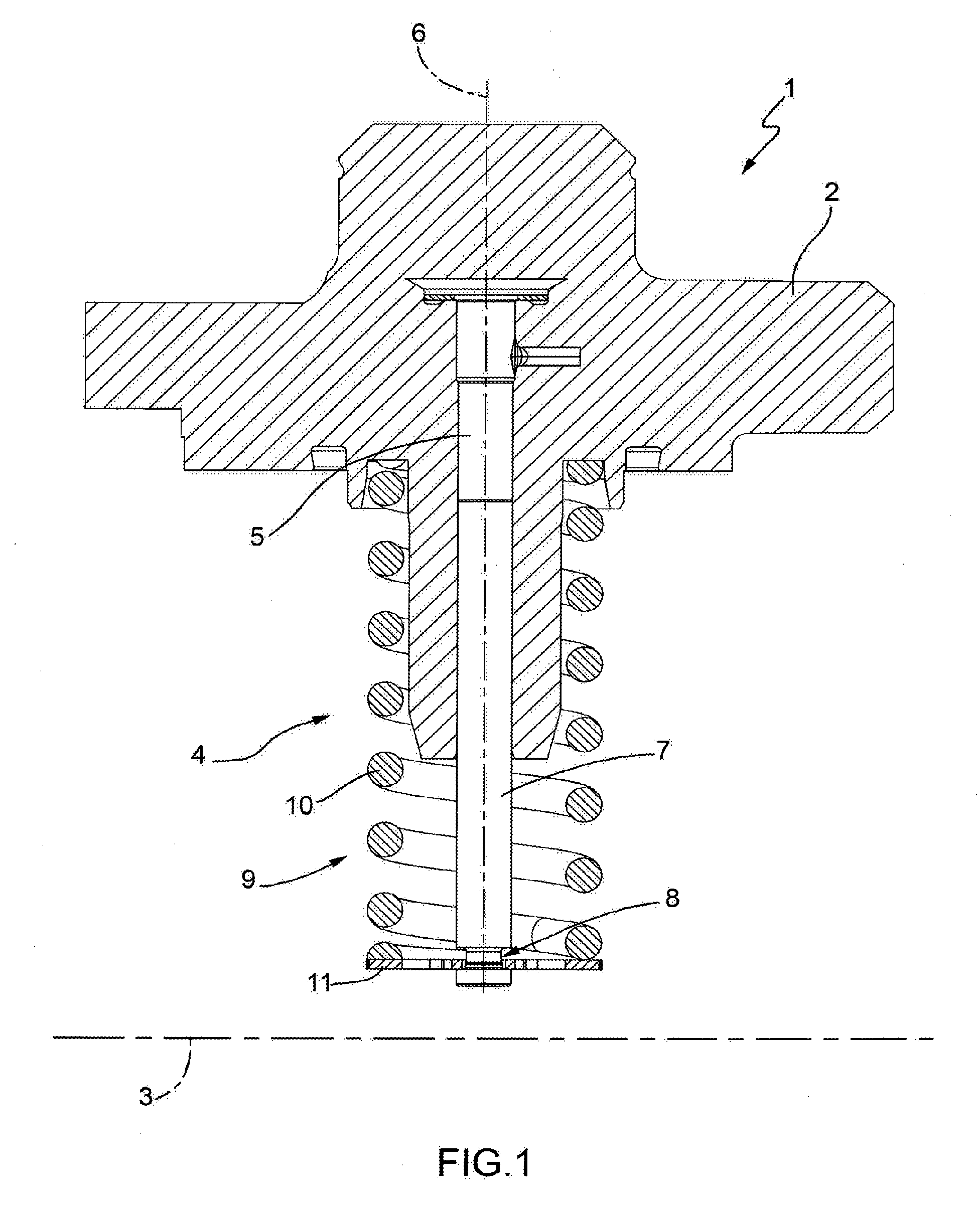
Figure 1 is a schematic cross-sectional view, with parts removed for the sake of clarity,
of a preferred embodiment of the pump unit according to the present invention;
Figure 2 is a side view of a first detail of Figure 1; and
Figure 3 is a plan view of a second detail of Figure 1.
[0013] With reference to Figure 1, 1 denotes, in its entirety, a pump unit for feeding fuel,
in particular diesel fuel, to an internal combustion engine (not shown).
[0014] The pump unit 1 comprises a pump body 2 provided with a central hole (not shown)
having a given longitudinal axis 3; a piston pump 4 designed to feed the fuel to the
said internal combustion engine (not shown); and a gear pump, known and not shown,
designed to feed the fuel to the pump 4.
[0015] The pump 4 comprises a plurality of cylinders 5 (only one of which is shown in Figure
1) which are formed in the pump body 2, are uniformly distributed around the axis
3 and have respective longitudinal axes 6 substantially perpendicular to the axis
3.
[0016] Each cylinder 5 is slidably engaged by an associated piston 7 which is mounted inside
the cylinder 5 coaxially with the axis 6, has a diameter D1 and is provided with an
annular groove 8 (Figure 2) which is formed on an outer surface of the piston 7 at
an intermediate point of the piston 7 itself and has a diameter D2 smaller than the
diameter D1.
[0017] The pistons 7 are displaced with an alternating rectilinear movement along the associated
cylinders 5 by an actuating device 9 comprising, in the case in question, a drive
shaft (not shown) which extends through the pump body 2 coaxially with the axis 3,
is mounted so as to rotate, relative to the pump body 2, about the axis 3 and has
an eccentric portion engaged rotatably, via a rolling bearing (not shown), through
a sleeve (not shown).
[0018] The sleeve (not shown) has a longitudinal axis parallel to the axis 3 and is bounded
externally by a cylindrical surface provided with a plurality of flat faces equal
in number to the number of cylinders 5 and each facing a respective disk element (not
shown) arranged between an associated piston 7 and the flat face itself.
[0019] The actuating device 9 furthermore comprises, for each piston 7, a respective spring
10 which is mounted coaxially with the associated axis 6, is arranged between the
pump body 2 and a substantially flat support plate 11 mounted on the piston 7, perpendicularly
with respect to the associated axis 6, and is designed to displace - and normally
keep - the piston 7 itself in contact with the associated disk element (not shown).
[0020] Following rotation of the drive shaft (not shown), each piston 7 is displaced by
the associated spring 10 during an outward intake stroke for drawing the fuel into
the associated cylinder 5 and by the eccentric portion of the drive shaft (not shown),
by the sleeve (not shown) and by the associated washer (not shown) during a return
compression stroke for compressing the fuel contained inside the said associated cylinder
5.
[0021] In accordance with that shown in Figure 3, the plate 11 has an opening 12 which is
formed through the plate 11, parallel to the axis 6, has a plane S of symmetry substantially
coplanar with the axis 6, is bounded by a shaped side wall 13 and comprises a seat
14 for inserting the piston 7 through the plate 11, a seat 15 for engaging the piston
7 in the plate 11, and a communicating section 16 allowing passage between the seat
14 and the seat 15.
[0022] The seat 14 has a substantially circular shape, a centre C1 of curvature different
from the axis 6, and a diameter D3 slightly greater than the diameter D1 of the piston
7; and the seat 15 has a substantially circular shape, a centre C2 of curvature substantially
arranged along the axis 6, and a diameter D4 which is slightly smaller than the diameter
D1 of the piston 7 and slightly greater than the diameter D2 of the groove 8.
[0023] It should be pointed out, moreover, that the distance between the centres C1 and
C2 is smaller than the sum of the radii of curvature of the two seats 14 and 15.
[0024] The communicating section 16 is bounded laterally by two elastically deformable arms
17 which project from the wall 13 inside the opening 12, extend on opposite sides
of the plane S and have respective free ends 18 provided, in the case in question,
with respective holes 19 formed in the plate 11, parallel to the axis 6.
[0025] The arms 17 are arranged, normally, in an initial narrow configuration (Figure 3)
where the section 16 has a width L1, measured perpendicularly with respect to the
plane S, which is slightly smaller than the diameter D2 of the groove 8 and where
each arm 17 has a substantially V-shaped form and cooperates with the other arm 17
so as to define part of the seat 14 and part of the seat 15.
[0026] The opening 12 further comprises two recesses 20, which are formed on opposite sides
of the plane S and are each bounded by the wall 13 and by an associated arm 17.
[0027] In order to assemble the plate 11 on the piston 7:
the piston 7 is inserted into the insertion seat 14;
the plate 11 is displaced axially along the piston 7 so as to align radially the groove
8 with the communicating section 16;
the arms 17 are splayed inside the associated recesses 20, for example by means of
a splaying tool (not shown) engaged inside the holes 19, so as to provide the section
16 with a final widened configuration (not shown), where the section 16 has a width
L2, measured perpendicularly with respect to the plane S, greater than the width L1
and at least equal to the diameter of the groove 8;
the piston 7 is displaced radially from the seat 14 into the engaging seat 15 so as
to move the groove 8 through the section 16; and
the arms 17 are released so as to radially lock the piston 7 inside the seat 15.
[0028] Since the groove 8 has, in the case in question, a height H greater than the thickness
of the plate 11, the plate 11 is finally displaced axially in contact with the piston
7.
[0029] The final widened configuration of the arms 17 allows the piston 7 to be displaced
radially from the seat 14 into the seat 15 without interfering with the section 16
and therefore avoids damage to the groove 8, separation of metal particles from the
piston 7, reduction in the fatigue strength of the piston 7 and seizing of the piston
7 inside the cylinder 5.
1. Pump unit for feeding fuel, preferably diesel fuel, to an internal combustion engine,
the pump unit comprising a pump body (2); at least one cylinder (5) formed in the
pump body (2); a piston (7), which is slideably engaged inside the cylinder (5) and
has at least one first diameter (D2); a support plate (11) mounted on the piston (7);
a spring (10) arranged between the pump body (2) and the support plate (11) for displacing
the piston (7) during an intake stroke for drawing the fuel into the cylinder (5);
and an actuating device for displacing the piston (7) during a compression stroke
for compressing the fuel contained inside the said cylinder (5); the support plate
(11) having an opening (12) which is formed through the support plate (11), parallel
to a longitudinal axis (6) of the piston (7), and comprises a seat (14) for inserting
the piston (7) through the support plate (11), a seat (15) for engaging the piston
(7) in the support plate (11), and a communicating section (16) for allowing the piston
(7) to pass between the insertion seat (14) and the engaging seat (15); the communicating
section (16) having, in an initial narrow configuration thereof, a first width (L1)
which is slightly smaller than the said first diameter (D2); and being characterized in that the communicating section (16) is bounded laterally by two elastically deformable
arms (17) each having a respective free end (18).
2. Pump unit according to Claim 1, wherein the communicating section (16) has, in a final
widened configuration thereof following widening of the two arms (17), a second width
(L2) at least equal to the said first diameter (D2).
3. Pump unit according to Claim 2, wherein the arms (17) have respective gripping means
(19) designed to allow displacement of the said arms (17) into the final widened configuration.
4. Pump unit according to Claim 2 or 3, wherein the arms (17) have respective gripping
seats (19) designed to be engaged by at least one splaying tool for displacing the
arms (17) into the final widened configuration.
5. Pump unit according to any one of the preceding claims, wherein the insertion seat
(14) and the engaging seat (15) are substantially circular.
6. Pump unit according to Claim 5, wherein the centres of curvature (Cl, C2) of the insertion
and engaging seats (14, 15) are arranged at a distance from one another less than
the sum of the radii of curvature of the said insertion and engaging seats (14, 15).
7. Pump unit according to any one of the preceding claims, wherein the said opening (12)
has, furthermore, two recesses (20) arranged on opposite sides of the communicating
section (16) for receiving the arms (17) following elastic deformation of the said
arms (17).
8. Pump unit according to any one of the preceding claims, wherein the piston (7) has
a second diameter (D1) and comprises at least one annular groove (8) which is formed
on the outer surface of the piston (7) and has the said first diameter (D2).
9. Pump unit according to Claim 8, wherein the insertion seat (14) has a third diameter
(D3) slightly greater than the second diameter (D1) and the engaging seat (15) has
a fourth diameter (D4) slightly greater than the first diameter (D2) and slightly
smaller than the second diameter (D1).
10. Pump unit according to Claim 8 or 9, wherein the annular groove (8) has a height (H),
measured parallel to the said axis (6), which is greater than a thickness of the support
plate (11).
11. Pump unit according to any one of the preceding claims, wherein the two arms (17)
project inside the opening (12) from a side wall (13) of the said opening (12).
12. Pump unit according to Claim 11, wherein, at least when the arms (17) are arranged
in their initial narrow configuration, each arm (17) has a substantially V-shaped
form and cooperates with the other arm (17) so as to define part of the insertion
seat (14) and part of the engaging seat (15).
13. Method for assembling a pump unit for feeding fuel, preferably diesel fuel, to an
internal combustion engine, the pump unit comprising a pump body (2); at least one
cylinder (5) formed in the pump body (2); a piston (7), which is slidably engaged
inside the cylinder (5), extends through a support plate (11) and has at least one
first diameter (D2); a spring (10) arranged between the pump body (2) and the support
plate (11) for displacing the piston (7) during an intake stroke for drawing the fuel
into the cylinder (5); and an actuating device for displacing the piston (7) during
a compression stroke for compressing the fuel contained inside the said cylinder (5);
the support plate (11) having an opening (12), which is formed through the support
plate (11), parallel to a longitudinal axis (6) of the piston (7), and comprises a
seat (14) for inserting the piston (7) through the support plate (11), a seat (15)
for engaging the piston (7) in the support plate (11), and a communicating section
(16) for allowing the piston (7) to pass between the insertion seat (14) and the engaging
seat (15); the communicating section (16) being bounded laterally by two elastically
deformable arms (17) each having a respective free end (18) and having, in an initial
narrow configuration thereof, a first width (L1) which is slightly smaller than the
said first diameter (D2), wherein the piston (7) has a second diameter (D1) and comprises
at least one annular groove (8) which is formed on the outer surface of the piston
(7) and has the said first diameter (D2), and wherein the annular groove (8) is formed
at an intermediate point of the piston (7) and has a height (H), measured parallel
to the said axis (6), greater than a thickness of the support plate (11); the method
comprising the steps of:
introducing the piston (7) into the insertion seat (14);
axially displacing the piston (7) and the support plate (11) with respect to each
other through the insertion seat (14) so as to align the annular groove (8) with the
communicating section (16);
widening the two arms (17) so as to impart to the communicating section (16) a final
widened configuration, where the communicating section (16) has a second width (L2)
at least equal to the said first diameter (D2);
displacing the piston (7) and the support plate (11) with respect to each other transversely
with respect to the said axis (6) so as to displace the piston (7) from the insertion
seat (14) into the engaging seat (15) through the communicating section (16);
radially displacing the piston (7) and the support plate (11) with respect to each
other so as to move the annular groove (8) through the communicating section (16);
and axially displacing the piston (7) and the support plate (11) with respect to each
other through the engaging seat (15) so as to lock axially the support plate (11)
against the said piston (7).
14. Method according to Claim 13, wherein the piston (7) is displaced from the insertion
seat (14) into the engaging seat (15) without interfering with the communicating section
(16).
15. Method according to Claim 13 or 14 and further comprising the step of:
releasing the two arms (17) so as to radially lock the piston (7) inside the engaging
seat (15).
1. Pumpeneinheit zur Zufuhr von Kraftstoff, vorzugsweise Dieselkraftstoff, an einen Verbrennungsmotor,
wobei die Pumpeneinheit umfasst: einen Pumpenkörper (2); mindestens einen im Pumpenkörper
(2) ausgebildeten Zylinder (5); einen Kolben (7), der im Inneren des Zylinders (5)
gleitbar angeordnet ist und mindestens einen ersten Durchmesser (D2) hat; eine am
Kolben (7) montierte Stützplatte (11); eine zwischen dem Pumpenkörper (2) und der
Stützplatte (11) angeordnete Feder (10) zum Verschieben des Kolbens (7) während eines
Ansaugtaktes, um den Kraftstoff in den Zylinder (5) einzusaugen; und eine Betätigungsvorrichtung
zum Verschieben des Kolbens (7) während eines Verdichtungstaktes, um den im Inneren
des Zylinders (5) enthaltenen Kraftstoff zu verdichten; wobei die Stützplatte (11)
eine Öffnung (12) hat, die durch die Stützplatte (11) parallel zu einer Längsachse
(6) des Kolbens (7) verläuft und einen Sitz (14) zum Einfügen des Kolbens (7) durch
die Stützplatte (11), sowie einen Sitz (15) für einen Eingriff des Kolbens (7) in
der Stützplatte (11) und einen Verbindungsbereich (16) umfasst, damit der Kolben (7)
zwischen dem Einfügungssitz (14) und dem Eingriffssitz (15) verlaufen kann; wobei
der Verbindungsbereich (16) in einer anfänglichen engen Konfiguration davon eine erste
Breite (L1) hat, die geringfügig kleiner als der erste Durchmesser (D2) ist; dadurch gekennzeichnet, dass der Verbindungsbereich (16) seitlich von zwei elastisch verformbaren Armen (17) begrenzt
ist, die jeweils ein jeweiliges freies Ende (18) haben.
2. Pumpeneinheit nach Anspruch 1, wobei der Verbindungsbereich (16) in einer endgültigen
aufgeweiteten Konfiguration davon, nach erfolgter Aufweitung der zwei Arme (17), eine
zweite Breite (L2) hat, die mindestens dem ersten Durchmesser (D2) entspricht.
3. Pumpeneinheit nach Anspruch 2, wobei die Arme (17) jeweilige Greifmittel (19) haben,
die so ausgebildet sind, dass sie ein Verschieben der Arme (17) in die endgültige
aufgeweitete Konfiguration zulassen.
4. Pumpeneinheit nach Anspruch 2 oder 3, wobei die Arme (17) jeweilige Greifmittel (19)
haben, die so ausgebildet sind, dass darin mindestens ein Spreizmittel eingreifen
kann, um die Arme (17) in die endgültige aufgeweitete Konfiguration zu verschieben.
5. Pumpeneinheit nach einem der vorstehend aufgeführten Ansprüche, wobei der Einfügungssitz
(14) und der Eingriffssitz (15) im Wesentlichen kreisförmig sind.
6. Pumpeneinheit nach Anspruch 5, wobei die Zentren der Krümmung (C1, C2) der Einfügungs-
und Eingriffssitze (14, 15) in einem Abstand voneinander angeordnet sind, der kleiner
als die Summe der Krümmungsradien der Einfügungs- und Eingriffssitze (14, 15) ist.
7. Pumpeneinheit nach einem der vorstehend aufgeführten Ansprüche, wobei die Öffnung
(12) weiterhin zwei Rücksprünge (20) hat, die an gegenüberliegenden Seiten des Verbindungsbereichs
(16) angeordnet sind, um die Arme (17) nach erfolgter elastischer Verformung der Arme
(17) aufzunehmen.
8. Pumpeneinheit nach einem der vorstehend aufgeführten Ansprüche, wobei der Kolben (7)
einen zweiten Durchmesser (D1) hat und mindestens eine ringförmige Nut (8) umfasst,
die an der äußeren Oberfläche des Kolbens (7) ausgebildet ist und den ersten Durchmesser
(D2) aufweist.
9. Pumpeneinheit nach Anspruch 8, wobei der Einfügungssitz (14) einen dritten Durchmesser
(D3) hat, der geringfügig größer als der zweite Durchmesser (D1) ist, und wobei der
Eingriffssitz (15) einen vierten Durchmesser (D4) hat, der geringfügig größer als
der erste Durchmesser (D2) und geringfügig kleiner als der zweite Durchmesser (D1)
ist.
10. Pumpeneinheit nach Anspruch 8 oder 9, wobei die ringförmige Nut (8), parallel zur
Achse (6) gemessen, eine Höhe (H) hat, die größer als eine Dicke der Stützplatte (11)
ist.
11. Pumpeneinheit nach einem der vorstehend aufgeführten Ansprüche, wobei die zwei Arme
(17) von einer Seitenwand (13) der Öffnung (12) aus im Inneren der Öffnung (12) hervorragen.
12. Pumpeneinheit nach Anspruch 11, wobei, mindestens wenn die Arme (17) in ihrer anfänglichen
engen Konfiguration angeordnet sind, jeder Arm (17) eine im Wesentlichen V-förmige
Form aufweist und mit dem anderen Arm (17) zusammenwirkt, um einen Teil des Einfügungssitzes
(14) und einen Teil des Eingriffssitzes (15) zu definieren.
13. Verfahren zur Montage einer Pumpeneinheit zur Zufuhr von Kraftstoff, vorzugsweise
Dieselkraftstoff, an einen Verbrennungsmotor, wobei die Pumpeneinheit umfasst: einen
Pumpenkörper (2); mindestens einen im Pumpenkörper (2) ausgebildeten Zylinder (5);
einen Kolben (7), der im Inneren des Zylinders (5) gleitbar angeordnet ist, sich durch
eine Stützplatte (11) erstreckt und mindestens einen ersten Durchmesser (D2) hat;
eine zwischen dem Pumpenkörper (2) und der Stützplatte (11) angeordnete Feder (10)
zum Verschieben des Kolbens (7) während eines Ansaugtaktes, um den Kraftstoff in den
Zylinder (5) einzusaugen; und eine Betätigungsvorrichtung zum Verschieben des Kolbens
(7) während eines Verdichtungstaktes, um den im Inneren des Zylinders (5) enthaltenen
Kraftstoff zu verdichten; wobei die Stützplatte (11) eine Öffnung (12) hat, die durch
die Stützplatte (11) parallel zu einer Längsachse (6) des Kolbens (7) verläuft und
einen Sitz (14) zum Einfügen des Kolbens (7) durch die Stützplatte (11), sowie einen
Sitz (15) für einen Eingriff des Kolbens (7) in der Stützplatte (11) und einen Verbindungsbereich
(16) umfasst, damit der Kolben (7) zwischen dem Einfügungssitz (14) und dem Eingriffssitz
(15) verlaufen kann; wobei der Verbindungsbereich (16) seitlich von zwei elastisch
verformbaren Armen (17) begrenzt ist, die jeweils ein jeweiliges freies Ende (18)
und, in einer anfänglichen engen Konfiguration davon, eine erste Breite (L1) haben,
die geringfügig kleiner als der erste Durchmesser (D2) ist, wobei der Kolben (7) einen
zweiten Durchmesser (D1) hat und mindestens eine ringförmige Nut (8) umfasst, die
an der äußeren Oberfläche des Kolbens (7) ausgebildet ist, wobei der Kolben den ersten
Durchmesser (D2) hat, und wobei die ringförmige Nut (8) an einem Zwischenpunkt des
Kolbens (7) ausgebildet ist und, parallel zur Achse (6) gemessen, eine Höhe (H) hat,
die größer als eine Dicke der Stützplatte (11) ist; wobei das Verfahren die folgenden
Schritte umfasst:
Einfügen des Kolbens (7) in den Einfügungssitz (14); Axiales Verschieben des Kolbens
(7) und der Stützplatte (11) im Verhältnis zueinander durch den Einfügungssitz (14),
um die ringförmige Nut (8) zum Verbindungsbereich (16) auszurichten; Aufweiten der
zwei Arme (17), um dem Verbindungsbereich (16) eine endgültige aufgeweitete Konfiguration
zu verleihen, wobei der Verbindungsbereich (16) eine zweite Breite (L2) hat, die mindestens
dem ersten Durchmesser (D2) entspricht;
Verschieben des Kolbens (7) und der Stützplatte (11) im Verhältnis zueinander und
quer zur Achse (6), um den Kolben (7) vom Einfügungssitz (14) in den Eingriffssitz
(15) durch den Verbindungsbereich (16) zu verschieben; Radiales Verschieben des Kolbens
(7) und der Stützplatte (11) im Verhältnis zueinander, um die ringförmige Nut (8)
durch den Verbindungsbereich (16) zu bewegen; und
Axiales Verschieben des Kolbens (7) und der Stützplatte (11) im Verhältnis zueinander
durch den Eingriffssitz (15), um die Stützplatte (11) gegen den Kolben (7) axial zu
verriegeln.
14. Verfahren nach Anspruch 13, wobei der Kolben (7) vom Einfügungssitz (14) in den Eingriffssitz
(15) verschoben wird, ohne den Verbindungsbereich (16) zu beeinträchtigen.
15. Verfahren nach Anspruch 13 oder 14, wobei das Verfahren weiterhin den folgenden Schritt
umfasst:
Freigeben der zwei Arme (17), um den Kolben (7) im Inneren des Eingriffssitzes (15)
radial zu verriegeln.
1. Unité de pompe destinée à l'alimentation en carburant, de préférence en carburant
diesel, d'un moteur à combustion interne, l'unité de pompe comprenant un corps de
pompe (2) ; au moins un cylindre (5) formé dans le corps de pompe (2) ; un piston
(7) qui est engagé de manière coulissante à l'intérieur du cylindre (5) et présente
au moins un premier diamètre (D2) ; une plaque de support (11) montée sur le piston
(7) ; un ressort (10) disposé entre le corps de pompe (2) et la plaque de support
(11) pour déplacer le piston (7) pendant une course d'admission pour aspirer le carburant
à l'intérieur du cylindre (5) ; et un dispositif d'actionnement pour déplacer le piston
(7) pendant une course de compression pour comprimer le carburant contenu à l'intérieur
dudit cylindre (5) ; la plaque de support (11) présentant une ouverture (12) qui est
formée à travers la plaque de support (11), parallèlement à un axe longitudinal (6)
du piston (7), et comprend un siège (14) pour insérer le piston (7) à travers la plaque
de support (11), un siège (15) pour engager le piston (7) dans la plaque de support
(11), et une section de communication (16) pour permettre au piston (7) de passer
entre le siège d'insertion (14) et le siège d'engagement (15) ; la section de communication
(16) présentant, dans une configuration étroite initiale de celle-ci, une première
largeur (L1) qui est légèrement inférieure audit premier diamètre (D2) ; et caractérisée en ce que la section de communication (16) est limitée latéralement par deux bras déformables
élastiquement (17) ayant chacun une extrémité libre (18) respective.
2. Unité de pompe selon la revendication 1, dans laquelle la section de communication
(16) présente, dans une configuration élargie finale de celle-ci suite à l'élargissement
des deux bras (17), une deuxième largeur (L2) au moins égale audit premier diamètre
(D2).
3. Unité de pompe selon la revendication 2, dans laquelle les bras (17) présentent des
moyens de préhension (19) respectifs conçus pour permettre le déplacement desdits
bras (17) dans la configuration élargie finale.
4. Unité de pompe selon la revendication 2 ou 3, dans laquelle les bras (17) présentent
des sièges de préhension (19) respectifs conçus pour être engagés par au moins un
outil d'écartement pour déplacer les bras (17) dans la configuration élargie finale.
5. Unité de pompe selon l'une quelconque des revendications précédentes, dans laquelle
le siège d'insertion (14) et le siège d'engagement (15) sont sensiblement circulaires.
6. Unité de pompe selon la revendication 5, dans laquelle les centres de courbure (C1,
C2) des sièges d'insertion et d'engagement (14, 15) sont disposés à une distance l'un
de l'autre qui est inférieure à la somme des rayons de courbure desdits sièges d'insertion
et d'engagement (14, 15).
7. Unité de pompe selon l'une quelconque des revendications précédentes, dans laquelle
ladite ouverture (12) présente, en outre, deux évidements (20) disposés sur des côtés
opposés de la section de communication (16) pour recevoir les bras (17) suite à la
déformation élastique desdits bras (17).
8. Unité de pompe selon l'une quelconque des revendications précédentes, dans laquelle
le piston (7) présente un deuxième diamètre (D1) et comprend au moins une rainure
annulaire (8) qui est formée sur la surface extérieure du piston (7) et présente ledit
premier diamètre (D2).
9. Unité de pompe selon la revendication 8, dans laquelle le siège d'insertion (14) présente
un troisième diamètre (D3) légèrement supérieur au deuxième diamètre (D1) et le siège
d'engagement (15) présente un quatrième diamètre (D4) légèrement supérieur au premier
diamètre (D2) et légèrement inférieur au deuxième diamètre (D1).
10. Unité de pompe selon la revendication 8 ou 9, dans laquelle la rainure annulaire (8)
présente une hauteur (H), mesurée parallèlement audit axe (6), qui est supérieure
à une épaisseur de la plaque de support (11).
11. Unité de pompe selon l'une quelconque des revendications précédentes, dans laquelle
les deux bras (17) font saillie à l'intérieur de l'ouverture (12) à partir d'une paroi
latérale (13) de ladite ouverture (12).
12. Unité de pompe selon la revendication 11, dans laquelle, au moins lorsque les bras
(17) sont disposés dans leur configuration étroite initiale, chaque bras (17) présente
une forme sensiblement en forme de V et coopère avec l'autre bras (17) de manière
à définir une partie du siège d'insertion (14) et une partie du siège d'engagement
(15).
13. Procédé d'assemblage d'une unité de pompe destinée à l'alimentation en carburant,
de préférence en carburant diesel, d'un moteur à combustion interne, l'unité de pompe
comprenant un corps de pompe (2) ; au moins un cylindre (5) formé dans le corps de
pompe (2) ; un piston (7) qui est engagé de manière coulissante à l'intérieur du cylindre
(5), s'étend à travers une plaque de support (11) et présente au moins un premier
diamètre (D2) ; un ressort (10) disposé entre le corps de pompe (2) et la plaque de
support (11) pour déplacer le piston (7) pendant une course d'admission pour aspirer
le carburant à l'intérieur du cylindre (5) ; et un dispositif d'actionnement pour
déplacer le piston (7) pendant une course de compression pour comprimer le carburant
contenu à l'intérieur dudit cylindre (5) ; la plaque de support (11) présentant une
ouverture (12), qui est formée à travers la plaque de support (11), parallèlement
à un axe longitudinal (6) du piston (7), et comprend un siège (14) pour insérer le
piston (7) à travers la plaque de support (11), un siège (15) pour engager le piston
(7) dans la plaque de support (11), et une section de communication (16) pour permettre
au piston (7) de passer entre le siège d'insertion (14) et le siège d'engagement (15)
; la section de communication (16) étant limitée latéralement par deux bras déformables
élastiquement (17) ayant chacun une extrémité libre (18) respective et présentant,
dans une configuration étroite initiale de celle-ci, une première largeur (L1) qui
est légèrement inférieure audit premier diamètre (D2), le piston (7) présentant un
deuxième diamètre (D1) et comprenant au moins une rainure annulaire (8) qui est formée
sur la surface extérieure du piston (7) et présente ledit premier diamètre (D2), et
la rainure annulaire (8) étant formée à un point intermédiaire du piston (7) et présentant
une hauteur (H), mesurée parallèlement audit axe (6), qui est supérieure à une épaisseur
de la plaque de support (11) ; le procédé comprenant les étapes de
introduction du piston (7) à l'intérieur du siège d'insertion (14) ;
déplacement axial du piston (7) et de la plaque de support (11) l'un par rapport à
l'autre à travers le siège d'insertion (14) de manière à aligner la rainure annulaire
(8) avec la section de communication (16) ;
élargissement des deux bras (17) de manière à donner à la section de communication
(16) une configuration élargie finale, où la section de communication (16) présente
une deuxième largeur (L2) au moins égale audit premier diamètre (D2) ; déplacement
du piston (7) et de la plaque de support (11) l'un par rapport à l'autre transversalement
par rapport audit axe (6) de manière à déplacer le piston (7) à partir du siège d'insertion
(14) dans le siège d'engagement (15) à travers la section de communication (16) ;
déplacement radial du piston (7) et de la plaque de support (11) l'un par rapport
à l'autre de manière à déplacer la rainure annulaire (8) à travers la section de communication
(16) ;
et déplacement axial du piston (7) et de la plaque de support (11) l'un par rapport
à l'autre à travers le siège d'engagement (15) de manière à bloquer axialement la
plaque de support (11) contre ledit piston (7).
14. Procédé selon la revendication 13, dans lequel le piston (7) est déplacé à partir
du siège d'insertion (14) dans le siège d'engagement (15) sans interférer avec la
section de communication (16).
15. Procédé selon la revendication 13 ou 14 et comprenant en outre l'étape de :
libération des deux bras (17) de manière à bloquer radialement le piston (7) à l'intérieur
du siège d'engagement (15).

REFERENCES CITED IN THE DESCRIPTION
This list of references cited by the applicant is for the reader's convenience only.
It does not form part of the European patent document. Even though great care has
been taken in compiling the references, errors or omissions cannot be excluded and
the EPO disclaims all liability in this regard.
Patent documents cited in the description