| (19) |
 |
|
(11) |
EP 2 949 849 A1 |
| (12) |
EUROPEAN PATENT APPLICATION |
| (43) |
Date of publication: |
|
02.12.2015 Bulletin 2015/49 |
| (22) |
Date of filing: 28.10.2014 |
|
| (51) |
International Patent Classification (IPC):
|
|
| (84) |
Designated Contracting States: |
|
AL AT BE BG CH CY CZ DE DK EE ES FI FR GB GR HR HU IE IS IT LI LT LU LV MC MK MT NL
NO PL PT RO RS SE SI SK SM TR |
|
Designated Extension States: |
|
BA ME |
| (30) |
Priority: |
26.05.2014 SI 201400196
|
| (71) |
Applicant: INTECH-LES, razvojni center d.o.o. |
|
1381 Rakek (SI) |
|
| (72) |
Inventors: |
|
- Tadic , Petar
1386 Stari trg pri Lozu (SI)
- Virant, Mitja
1386 Stari trg pri Lozu (SI)
|
| (74) |
Representative: Ivancic, Bojan |
|
Inventio d.o.o.
Dolenjska cesta 11
1000 Ljubljana
1000 Ljubljana (SI) |
|
| |
|
| (54) |
Corner support hinge for a window and/or door |
(57) The present invention relates to a corner support hinge for a window and/or doors
to provide corner support of a frame of a window and/or door sash on a fixed frame,
comprising a frame corner, which can be fastened to a fixed frame, a sash corner,
which can be mounted to a frame sash by means of an adjustment screw guide for height
adjustment of a sash frame and a scissors mechanism, by means of which a frame corner
and a sash corner are movable relative to each other. It is provided for, according
to the present invention that a scissors mechanism (3) is movable by means of a shifting
element (8) arranged on a horizontal leg (1.1) of a corner (1) of the window and/or
door frame.
|
|
[0001] The present invention relates to a corner support hinge for a window and/or doors
to provide corner support of a frame of a window and/or door sash on a fixed frame,
comprising a frame corner, which can be fastened to a fixed frame, a sash corner,
which can be mounted to a frame sash by means of an adjustment screw guide for height
adjustment of a sash frame and a scissors mechanism, by means of which a frame corner
and a sash corner are movable relative to each other.
[0002] A support hinge of the above mentioned type is well known and comprises a corner,
which can be mounted to a frame sash of a window and/or door and a corner, which can
be fastened to a fixed window and/or door frame. Said corners are mutually connected
by a scissors mechanism being fixed essentially in a longitudinal direction of the
corners resulting in a fact that the frame sash adjustment relative to the fixed frame
in the horizontal direction can not be achieved.
[0003] It is the object of the present invention to create a window and/or door support
hinge which remedies drawbacks of the known solutions.
[0004] The object as set above is solved according to the present invention by a scissors
mechanism, with which a frame corner and a sash corner are movable relative to each
other, said scissors mechanism can be moved by means of a shifting element, arranged
on a horizontal leg of the corner of the window and/or door frame.
[0005] The invention is further described in detail by way of non-limiting preferred embodiment,
and with a reference to the accompanying drawing, where
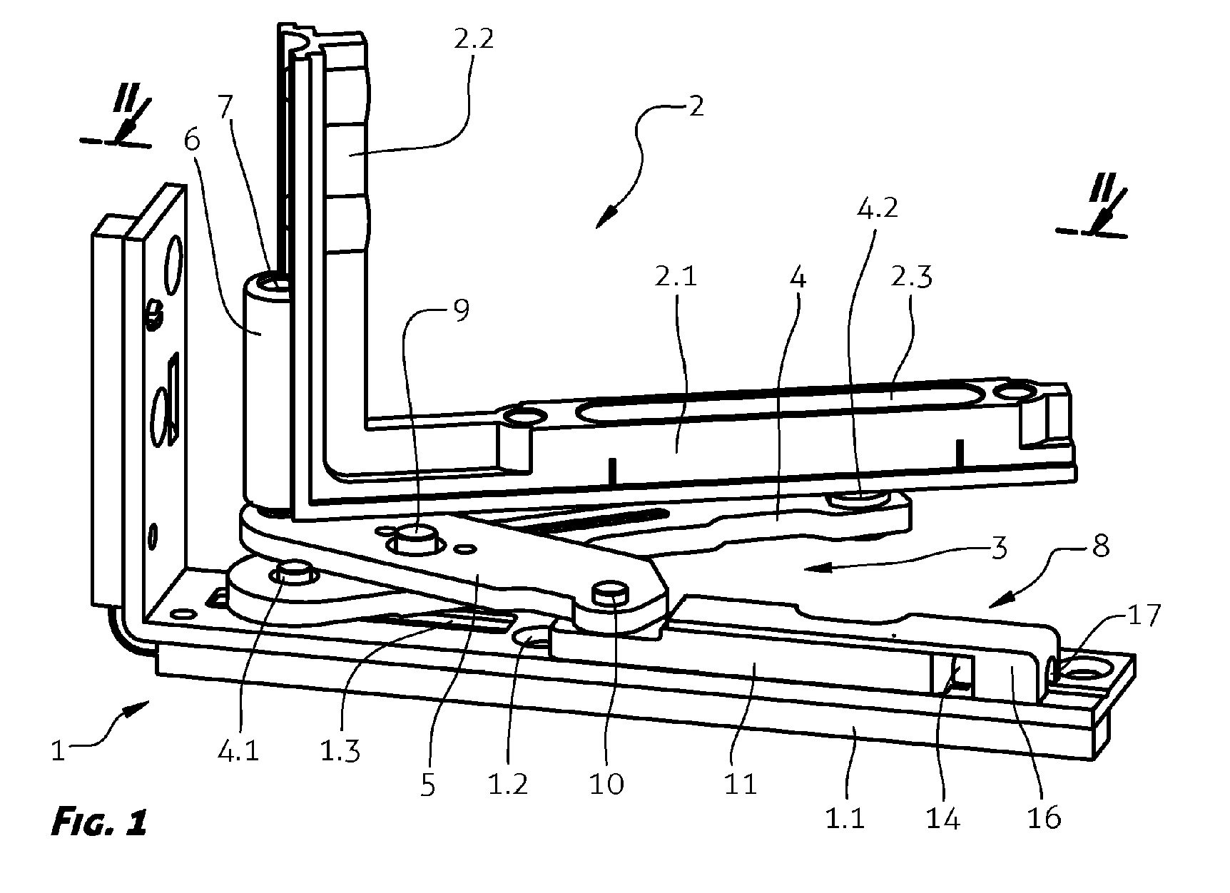
- Fig. 1
- shows a three-dimensional view of a support hinge according to the invention;
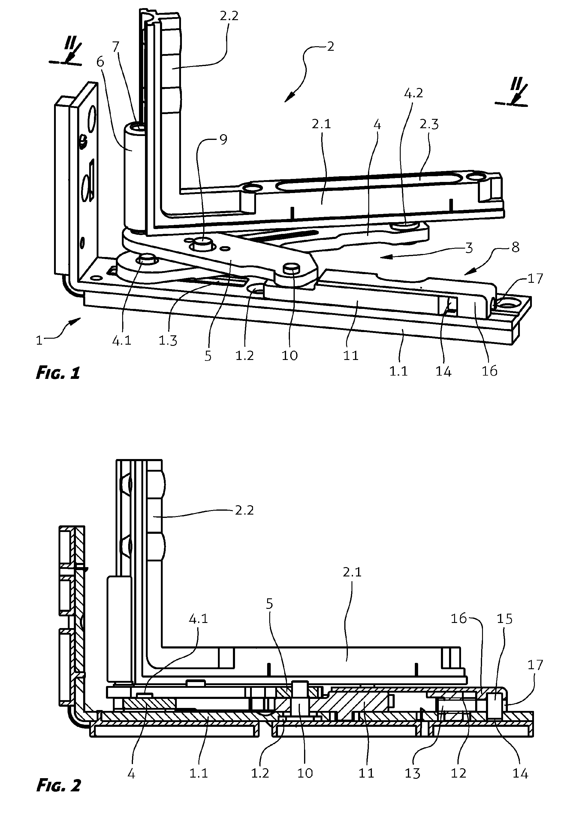
- Fig. 2
- shows a cross-sectional view of a hinge of Fig. 1 along the line II-II.
[0006] According to the present invention, a corner support hinge of the window and/or door
is intended to open and close windows and/or doors, i.e. turning around a vertical
axis, as well as tilting the window, i.e. rotating around a horizontal axis. Said
corner support hinge comprises an angle section 1 of a frame, that can be fastened
onto a fixed frame of a window and/or door, an angle section 2 of the sash, that can
be mounted on the sash frame, and a scissors mechanism 3, by which the angle section
2 is movable in relation to the angle section 1. Said scissors mechanism 3 comprises
a first arm 4 being articulated with the first end thereof to the horizontal leg 1.1
of the angle section 1 of the frame, and being articulated with the second end thereof
to a horizontal leg 2.1 of the angle section 2 of the sash. Furthermore, said scissors
mechanism 3 comprises a second arm 5 being articulated with the first end thereof
to a receptacle 6 for an adjustment screw 7, and being articulated with the second
end thereof to a shifting element 8. The arms 4, 5 are mutually articulated in a manner
known per se by means of a pin 9. Said receptacle 6 is integral with a vertical leg
2.2, whereas the shifting element 8 is arranged on said the horizontal leg 1.1.
[0007] In order to allow movement of the window and/or door sash in horizontal direction
in relation to the frame, said shifting element 8 on the horizontal leg 1.1 is arranged
movably in the longitudinal direction of the leg 1.1. To that end, said leg 1.1. is
formed with an elongated through-hole 1.2 intended to cooperate with pin 10, enabling
simultaneously articulated connection of said second arm 5 of the scissors mechanism
3 with the shifting element 8. Furthermore, said horizontal leg 1.1 is formed in the
area of the articulated connection with the first arm 4 of the scissors mechanism
3 with an additional through-hole 1.3 cooperating with a guide bar 4.1 of the first
arm 4. In addition, said horizontal leg 2.1 of the angle section 2 of the sash is
formed with an elongated thorugh-hole 2.3, cooperating with the second end of said
first arm 4 and, respectively, a bolt 4.2 placed therein.
[0008] Said shifting element 8 is formed of a slider 11 being arranged on the leg 1.1 and
slidingly movable in the longitudinal direction thereof, the first end of the slider
11 being articulated by means of the pin 10 with the second arm 5. The second end
i.e. the free end of the slider 11 is formed with a threaded hole 12 that cooperates
with a screw means 13 arranged on the leg 1.1, the threaded hole 12 and the screw
means 13 extending in parallel with said leg 1.1. In order to enable movement of the
slider 11 in the longitudinal direction of the leg 1.1, a depression 14 is provided
in the area of the free end of the leg 1.1, into which fits a free end 15 of the screw
means 13 where a torque may be introduced to rotate the screw means 13, for instance
by means of an appropriate tool. In the present embodiment, a head 15 of the screw
13 is arranged in said depression 14, said screw being acted upon by means of a screwdriver.
Moreover, said slider 11 and the screw means 13 are both protected against external
influences with a cover 16 having available only a slot 17 to provide free access
of said tool to enter torque into the screw means.
[0009] By turning the screw means 13, the slider 11 moves in the longitudinal direction
of the leg 1.1 of the angle section 1 of the window and/or door frame, the motion
of slider 11 being limited by the length of said elongated through-hole 1.2 in the
leg 1.1. The movement of the slider 11 in the longitudinal direction of the leg 1.1
is transferred via the scissors mechanism 3 to the angle section 2 of the window and/or
door sash, therefore ensuring a reliable and accurate window and/or door sash regulation
in the horizontal direction.
1. A corner support hinge for a window and/or doors to provide corner support of a frame
of a window and/or door sash on a fixed frame, comprising a frame corner, which can
be fastened to a fixed frame, a sash corner, which can be mounted to a frame sash
by means of an adjustment screw guide for height adjustment of a sash frame and a
scissors mechanism, by means of which a frame corner and a sash corner are movable
relative to each other, characterized in that a scissor mechanism (3) is movable by means of a shifting element (8) arranged on
a horizontal leg (1.1) of a corner (1) of a window and/or door frame.
2. A corner support hinge according to claim 1, characterized in that said shifting element (8) on the horizontal leg (1.1) is arranged movably in the
longitudinal direction of the leg (1.1) by means of cooperation of an elongated through-hole
(1.2) in the leg (1.1) and a pin (10), simultaneously enabling articulated connection
of a second arm (5) of the scissors mechanism (3) with the shifting element (8).
3. A corner support hinge according to claims 1 and 2, characterized in that said horizontal leg (1.1) is formed in the area of the articulated connection to
the first arm (4) of the scissors mechanism (3) with a through-hole (1.3), cooperating
with a guide bar (4.1) of the first arm (4).
4. A corner support hinge according to any of the preceding claims, characterized in that said shifting element (8) is formed of a slider (11) being arranged on the leg (1.1)
slidingly movable in the longitudinal direction thereof, the first end of the slider
(11) being articulated by means of the pin (10) with a second arm (5), whereas the
second, free end of the slider (11) is formed with a threaded hole (12), cooperating
with a screw means (13), arranged on the leg (1.1).
5. A corner support hinge according to any of the preceding claims, characterized in that in the area of the free end of the leg (1.1) is formed a depression (14), in which
is arranged a free end (15) of the screw means (13 into which a torque may be introduced
for the rotation of the screw means (13).
6. A corner support hinge according to claim 5, characterized in that said slider (11) and the screw means (13) are both covered with a cover bar (16).