| (19) |
 |
|
(11) |
EP 1 975 003 B1 |
| (12) |
EUROPEAN PATENT SPECIFICATION |
| (45) |
Mention of the grant of the patent: |
|
23.03.2016 Bulletin 2016/12 |
| (22) |
Date of filing: 28.03.2008 |
|
| (51) |
International Patent Classification (IPC):
|
|
| (54) |
Interior trim component and method of manufacturing the same
Innenverkleidungsteil und Herstellungsverfahren dafür
Composant de garniture intérieure et son procédé de fabrication
|
| (84) |
Designated Contracting States: |
|
DE FR GB |
| (30) |
Priority: |
30.03.2007 US 908990 P
|
| (43) |
Date of publication of application: |
|
01.10.2008 Bulletin 2008/40 |
| (73) |
Proprietor: GRUPO ANTOLIN-IRAUSA, S.A. |
|
09007 Burgos (ES) |
|
| (72) |
Inventors: |
|
- Pianowski, John C.
South Lyon, Michigan 48178 (US)
- Vanderpool, Vaughn D.
Fowlerville, Michigan 48836 (US)
|
| (74) |
Representative: Capitán García, Maria Nuria |
|
ARS Privilegium, S.L.
Felipe IV no. 10, bajo iz.
28014 Madrid
28014 Madrid (ES) |
| (56) |
References cited: :
JP-A- 2 028 018
JP-A- 2000 343 947
|
JP-A- 5 092 743
JP-U- 61 159 215
|
|
| |
|
|
|
|
| |
|
| Note: Within nine months from the publication of the mention of the grant of the European
patent, any person may give notice to the European Patent Office of opposition to
the European patent
granted. Notice of opposition shall be filed in a written reasoned statement. It shall
not be deemed to
have been filed until the opposition fee has been paid. (Art. 99(1) European Patent
Convention).
|
Related Application
Background
[0002] It is known in the art that vehicles, such as, for example, automotive vehicles,
include interior trim components. Typically, an interior trim component provides a
rigid and/or soft, aesthetically-pleasing surface that trims structure of a vehicle,
such as, for example, door structure, roof structure, instrument panel structure,
A-pillars, B-pillars, C-pillars, or the like.
[0003] Document
JP 5 092743 A shows an interior trim component corresponding to the preamble of claim 1. An interior
trim component according to the invention is defined by the features of claim 1 and
a method for manufacturing an interior trim component according to the invention is
defined by the features of claim 10.
Brief Description of the Drawings
[0004] The disclosure will now be described, by way of example, with reference to the accompanying
drawings, in which:
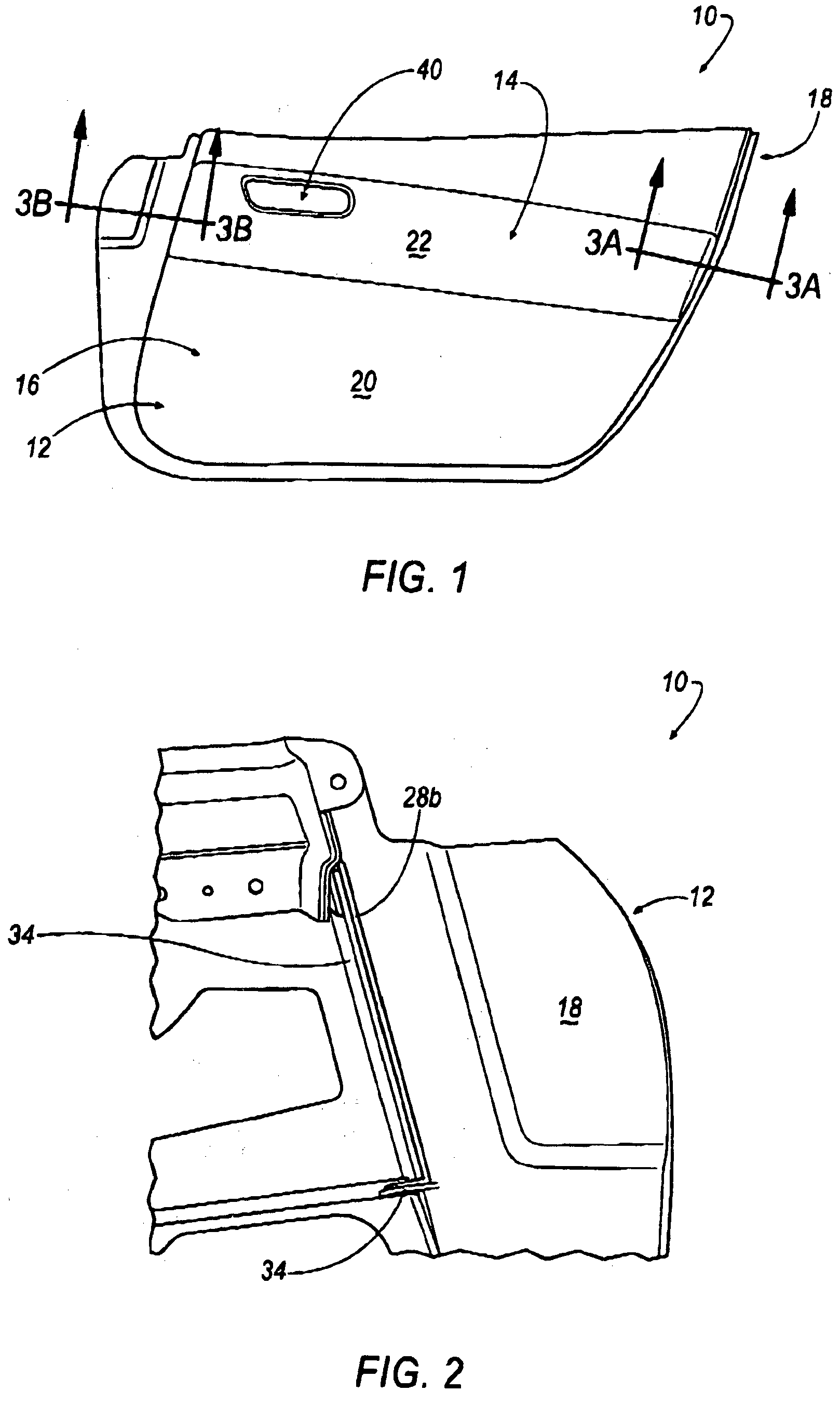
Figure 1 is a perspective view of the interior trim component in accordance with an
examplary embodiment of the invention;
Figure 2 is a partial perspective view of the interior trim component of Figure 1
in accordance with an exemplary embodiment of the invention;
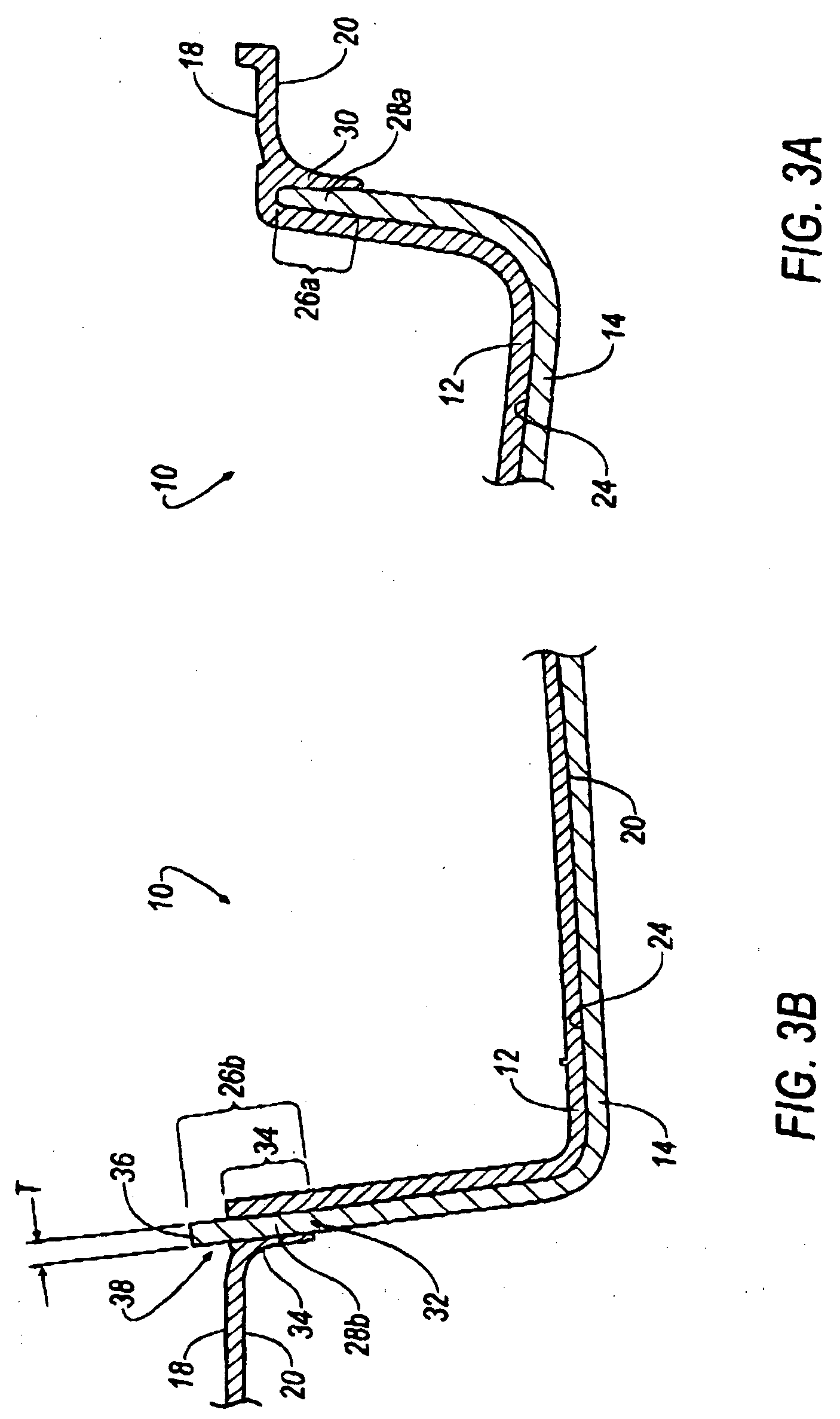
Figure 3A is a cross-sectional view of the interior trim component of Figure 1 in
accordance with an exemplary embodiment of the invention; and
Figure 3B is a cross-sectional view of the interior trim component of Figure 1 in
accordance with an exemplary embodiment of the invention.
Detailed Description
[0005] The Figures illustrate an exemplary embodiment of an interior trim component and
method of manufacturing the same in accordance with an embodiment of the invention.
It is to be generally understood that the nomenclature used herein is simply for convenience
and the terms used to describe the invention should be given the broadest meaning
by one of ordinary skill in the art.
[0006] Referring to Figures 1-3B, an interior trim component is shown generally at 10 according
to an embodiment. The interior trim component 10 is defined to include a vehicular
door geometry such that the interior trim component 10 functions as a panel for trimming
vehicular door structure (not shown). Although the interior trim component includes
a vehicular door geometry, it will be appreciated that the interior trim component
10 is not limited to a particular geometry; as such, the interior trim component 10
may include a geometry that trims vehicular roof structure, instrument panel structure,
pillar structure, or the like.
[0007] The interior trim component 10 is further defined to include a first portion, which
is shown generally at 12, and a second portion, which is shown generally at 14. Because
the interior trim component 10 is formed to include a vehicular door geometry, the
first portion 12 may be referred to as a body portion and the second portion 14 may
be referred to as a bolster portion.
[0008] When joined to door structure, the interior trim component 10 defines an A-surface
16 that faces and is exposed to a passenger compartment area of a vehicle and a B-surface
18 that faces the door structure. If desired, the body portion 12 is defined to include
a first A-surface portion 20 defined by a first color, and the bolster portion 14
is defined to include a second A-surface portion 22 defined by a second color that
is different from the first color.
[0009] It will be appreciated that an "A-surface" is a term of art that describes a surface
that generally faces the passenger compartment of a vehicle, and, as such, may be
alternatively referred to as an "inboard surface." Further, it will be appreciated
that a "B-surface" is a term of art that describes a surface that generally faces
away from the passage compartment of a vehicle, and, as such, may be referred to as
an "outboard surface." Although the disclosure includes the terms A- / inboard surface
and B- / outboard surface, it will be appreciated that the above terms are used in
reference to an embodiment of the invention and therefore do not limited the invention
to a particular embodiment. The terms used to describe the invention should be given
the broadest meaning by one of ordinary skill in the art.
[0010] The first and second A-surface portions 20, 22 may be further defined to include
an A-surface texture/grain characteristic. The A-surface portion 20 of the body portion
12 may be defined to include, for example, a first A-surface texture/grain, and the
A-surface portion 22 of the bolster portion 14 may be defined to include, for example,
a second A. surface texture/grain that is different from the first A-surface texture/grain.
[0011] According to an embodiment, the first A-surface texture/grain may be defined by a
relatively smooth A-surface texture/grain, and the second A-surface texture/grain
may be defined by a leather or fabric A-surface texture/grain. It will be appreciated
that above-described A-surface texture/grains are not limited to a smooth, leather,
or fabric texture/grain and that any desirable A-surface texture/grain pattern may
define the first and second A-surface portion 20, 22 of the interior trim component
10.
[0012] In general, the body portion 12 may be defined by a three-dimensional, substantially
rigid substrate material defining the vehicle door geometry. Although the bolster
portion 14 includes a thickness, T (Figure 3B), to define a three-dimensional geometry,
the bolster portion is generally defined to include a two-dimensional unit of material
that is applied over the body portion 12. Once the bolster portion 14 is applied over
the body portion 12, the bolster portion 14 defines a decorative, aesthetically-pleasing
A-surface portion 22. According to an embodiment, the bolster portion 14 may define
a fabric, leather, or faux leather unit of material.
[0013] Referring to Figures 3A and 3B, prior to applying the bolster portion 14 to the body
portion 12. an adhesive may be sprayed onto a rear, B-surface 24 of the bolster portion
14. According to an embodiment, the adhesive is applied over the entire B-surface
24 except as shown at 26a and 26b. However, it will be appreciated that the adhesive
may be applied over the A-surface portion 20 of the body portion 12 corresponding
to the positioning of the bolster portion 14; if the adhesive is applied to the A-surface
portion 20 of the body portion 12, the adhesive is not applied to the corresponding
A-surface portion 20 where portions 26a, 26b of the bolster portion 14 contact or
is otherwise placed proximate the body portion 12.
[0014] The first B-surface end portion 26a may define a first end portion of the bolster
portion 14, which is shown generally at 28a. The second B-surface end portion 26b
may define a second end portion of the bolster portion 14, which is shown generally
at 28b.
[0015] According to an embodiment, the first end portion 28a includes a geometry that may
be correspondingly-received within a U-shape valley or groove 30 formed in A-surface
portion 20 of the body portion 12. According to an embodiment, the first end portion
28a is tucked into the U-shape valley or groove 30 in a tucking operation or process.
According to an embodiment, the tucking operation or process may be defined by a well-known
tucking technique that is commonly referred to in the art as "KimeKomi."
[0016] Referring to Figure 3B, once the first end portion 28a is tucked into the U-shape
valley or groove 30, the B-surface 24 including the adhesive is joined to the A-surface
portion 20 of the body portion 12. Then, the second end portion 28b that does not
include the adhesive is tucked through a corresponding opening or passage 32 defined
by the body portion 12.
[0017] As seen in Figures 2 and 3B, the body portion 12 may includes one or more projections
34 that substantially perpendicularly extend away from the A-surface portion 20 and
the B-surface 18. When the second end portion 28b is tucked through the opening or
passage 32, the projections 34 may assist in the securing of the second end portion
28b.
[0018] According to an embodiment, the bolster portion 14 is defined to include a length
and width such that when the second end portion 28b is tucked into the opening or
passage 32, an end surface 36 (Figure 3B) of the second end portion 28b may be substantially
flat or flush with the B-surface 18 defined by the body portion 12. Accordingly, although
the second end portion 28b may be defined by a projection 38 that extends past the
B-surface 18 defined by the body portion 12, the control over the length and width
sizing of the bolster portion 14 may reduce scrap material of the bolster portion
14 such that the occurrence and existence of projections 38 are minimized when the
second end portion 28b is tucked into opening or passage 32.
[0019] Once the bolster portion 14 is attached to the body portion 12 as described above,
additional processing steps may be carried out. For example, one or more of the bolster
portion 14 and body portion 12 may be punched to define a door handle bezel opening
40 (Figure 1) or the like.
[0020] The present invention has been described with reference to certain exemplary embodiments
thereof. However, it will be readily apparent to those skilled in the art that it
is possible to embody the invention in specific forms other than those of the exemplary
embodiments described above. The exemplary embodiments are merely illustrative and
should not be considered restrictive in any way. The scope of the invention is defined
by the appended claims and their equivalents, rather than by the preceding description.
1. An interior trim component, comprising: a body portion (12) defining an inboard-surface,
and an outboard surface, wherein in the joined state of the interior trim component
to door structure, said inboard-surface faces and is exposed to a passenger compartment
area of a vehicle and said outboard surface faces the door structure, said body portion
(12) being defined by a three-dimensional, substantially rigid substrate, wherein
the body portion (12) is further defined by a groove (30) formed in the inboard-surface,
and a passage (32) extending through the body portion (12) from the inboard-surface
to the outboard-surface; and a bolster portion (14) including a first end portion
(28a), and a second end portion (28b), wherein the first end portion (28a) is disposed
in the groove (30) formed in the inboard-surface, wherein the second end portion (28b)
is disposed in the passage and wherein said passage is further defined by projections
(34) of body portion (12) that assist in securing of the second end portion (28b),
characterized in that the projections (34) of body portion (12) substantially perpendicularly extend away
from the inboard-surface and the outboard surface.
2. The interior trim component according to claim 1, wherein the second end portion (28b)
is further defined by an end surface.
3. The interior trim component according to claim 2, wherein the end surface of the bolster
portion (14) is substantially flush with the outboard-surface of the body portion
(12).
4. The interior trim component according to claim 2, wherein the end surface of the bolster
portion (14) extends through the passage and past the outboard-surface of the body
portion (12).
5. The interior trim component according to claim 2, wherein the end surface of the bolster
portion (14) extends into the passage and terminates prior to the outboard-surface
of the body portion (12).
6. The interior trim component according to claim 1, wherein the bolster portion is further
defined to include a rear surface, wherein the rear surface is further defined by
a first end portion (28a), a second end portion (28b), and an intermediate portion
between the first and second end portion (28b), wherein an adhesive is disposed exclusively
on the intermediate portion.
7. The interior trim component according to claim 1, wherein the groove (30) formed in
the inboard-surface of the body portion (12) includes a substantially U-shape groove
(30) defining a valley.
8. The interior trim component according to claim 1, wherein the groove (30) defines
means for securing the first end portion (28a) of the bolster portion (14).
9. The interior trim component according to claim 1, wherein the passage defines means
for securing the second end portion (28b) of the bolster portion (14).
10. A method for manufacturing an interior trim component (10), comprising the steps of:
providing a body portion (12) defined by an inboard-surface, and an outboard-surface,
wherein in the joined state of the interior trim component to door structure, said
inboard-surface faces and is exposed to a passenger compartment area of a vehicle
and said outboard surface faces the door structure, wherein the body portion (12)
is further defined by a groove (30) formed in the inboard-surface, and a passage extending
through the body portion (12) from the inboard-surface to the outboard-surface; providing
a bolster portion (14) including a first end portion (28a), and a second end portion
(28b); securing the first end portion (28a) of the bolster portion (14) in the groove
(30) formed in the inboard-surface; and securing the second end portion (28b) of the
bolster portion (14) in the passage, wherein the body portion (12) is defined by a
three-dimensional, substantially rigid substrate material wherein said passage is
further defined by projections (34) of body portion (12) that assist in securing of
the second end portion (28b), characterized in that the projections (34) of body portion (12) substantially perpendicularly extend away
from the inboard-surface and the outboard surface.
11. The method according to claim 10, wherein the securing the first end portion (28a)
step further comprises the step of tucking the first end portion (28a) in the groove
(30) formed in the inboard-surface, wherein the securing the second end portion (28b)
step further comprises the step of tucking the second end portion (28b) in the passage.
12. The method according to claim 10, wherein the second end portion (28b) is further
defined by an end surface.
13. The method according to claim 12, wherein the securing the second end portion (28b)
step is further defined by the step of locating the end surface of the bolster portion
(14) substantially flush with the outboard-surface of the body portion (12).
14. The method according to claim 12, wherein the securing the second end portion (28b)
step is further defined by the step of locating the end surface of the bolster portion
(14) through the passage and past the outboard-surface of the body portion (12).
15. The method according to claim 12, wherein the securing the second end portion (28b)
step is further defined by the step of locating the end surface of the bolster portion
(14) within the passage but prior to the outboard-surface of the body portion (12).
1. Innere Verkleidungskomponente, die folgende Elemente umfasst: einen Gehäuseabschnitt
(12), der eine Innenfläche und eine Außenfläche festlegt, wobei im miteinander verbundenen
Zustand der inneren Verkleidungskomponente und der Türstruktur die besagte Innenfläche
am Fahrgastraum des Fahrzeugs freiliegt und die genannte Außenfläche an der Türstruktur
anliegt, wobei der erwähnte Gehäuseabschnitt (12) aus einem starren dreidimensionalen
Trägermaterial besteht und dieser Abschnitt (12) außerdem eine in die Innenfläche
eingelassene Rille (30) besitzt und ein Durchlass (32) durch den Gehäuseabschnitt
(12) von der Innen- zur Außenseite führt, wobei ein Kissen (14) einen ersten Endabschnitt
(28a) und einen zweiten Endabschnitt (28b) umfasst und dieser erste Endabschnitt (28a)
in der Rille (30) der Innenfläche angebracht ist, wobei andererseits der zweite Endabschnitt
(28b) im Durchlass angebracht ist und dieser Durchlass von Vorsprüngen (34) gebildet
wird, die aus dem Gehäuseabschnitt (12) herausragen und den zweiten Endabschnitt (28b)
sichern, dadurch gekennzeichnet, dass die Vorsprünge (34) des Gehäuseabschnitts (12) im Wesentlichen im rechten Winkel
aus der Innen- und der Außenfläche herausragen.
2. Innere Verkleidungskomponente nach Anspruch 1, wobei der zweite Endabschnitt (28b)
außerdem durch eine Endfläche vorgegeben ist.
3. Innere Verkleidungskomponente nach Anspruch 2, wobei die Endfläche des Kissens (14)
im Wesentlichen bündig mit der Außenfläche des Gehäuseabschnitts (12) abschließt.
4. Innere Verkleidungskomponente nach Anspruch 2, wobei die Endfläche des Kissens (14)
durch den Durchlass und bis hinter die Außenfläche des Gehäuseabschnitts (12) verläuft.
5. Innere Verkleidungskomponente nach Anspruch 2, wobei sich die Endfläche des Kissens
(14) in den Durchlass hinein erstreckt und vor der Außenfläche des Gehäuseabschnitts
(12) endet.
6. Innere Verkleidungskomponente nach Anspruch 1, wobei das Kissen außerdem eine Rückfläche
umfasst, die durch einen ersten Endabschnitt (28a) und einen zweiten Endabschnitt
(28b) sowie durch einen Zwischenabschnitt zwischen dem ersten und dem zweiten Endabschnitt
(28b) gegeben ist, wobei Klebstoff ausschließlich auf den Zwischenabschnitt aufgetragen
wird.
7. Innere Verkleidungskomponente nach Anspruch 1, wobei die in die Innenfläche des Gehäuseabschnitts
(12) eingelassene Rille (30) eine im Wesentlichen u-förmige Rille (30) umfasst, die
eine Senke bildet.
8. Innere Verkleidungskomponente nach Anspruch 1, wobei die Rille (30) Mittel zur Sicherung
des ersten Endabschnitts (28a) des Kissens (14) vorgibt.
9. Innere Verkleidungskomponente nach Anspruch 1, wobei der Durchlass die Mittel zur
Sicherung des zweiten Endabschnitts (28b) des Kissens (14) vorgibt.
10. Herstellungsverfahren der inneren Verkleidungskomponente (10), bestehend aus folgenden
Schritten: Bereitstellung eines Gehäuseabschnitts (12), der durch eine Innenfläche
und eine Außenfläche festgelegt ist, wobei im miteinander verbundenen Zustand der
inneren Verkleidungskomponente und der Türstruktur die besagte Innenfläche am Fahrgastraum
des Fahrzeugs freiliegt und die genannte Außenfläche an der Türstruktur anliegt, wobei
der Gehäuseabschnitt (12) außerdem eine in die Innenfläche eingelassene Rille (30)
besitzt und ein Durchlass durch den Gehäuseabschnitt (12) von der Innen- zur Außenseite
führt, wobei ein Kissen (14) einen ersten Endabschnitt (28a) und einen zweiten Endabschnitt
(28b) umfasst und der erste Endabschnitt (28a) dieses Kissens (14) in der Rille (30)
der Innenfläche gesichert ist und andererseits der zweite Endabschnitt (28b) des Kissens
(14) im Durchlass gesichert ist, wobei der Gehäuseabschnitt (12) aus einem starren
dreidimensionalen Trägermaterial besteht und der genannte Durchlass von Vorsprüngen
(34) gebildet wird, die aus dem Gehäuseabschnitt (12) herausragen und den zweiten
Endabschnitt (28b) sichern, dadurch gekennzeichnet, dass die Vorsprünge (34) des Gehäuseabschnitts (12) im Wesentlichen im rechten Winkel
aus der Innen- und der Außenfläche herausragen.
11. Verfahren nach Anspruch 10, wobei der Verfahrensschritt der Sicherung des ersten Endabschnitts
(28a) auch das Stecken desselben (28a) in die Rille (30), welche in die Innenfläche
eingelassen ist, umfasst, und der Schritt zur Sicherung des zweiten Endabschnitts
(28b) das Stecken desselben (28b) in den Durchlass umfasst.
12. Verfahren nach Anspruch 10, wobei der zweite Endabschnitt (28b) außerdem durch eine
Endfläche vorgegeben ist.
13. Verfahren nach Anspruch 12, wobei der Verfahrensschritt der Sicherung des zweiten
Endabschnitts (28b) zusätzlich durch das Positionieren der Endfläche des Kissens (14)
vorgegeben ist, das im Wesentlichen bündig mit der Außenfläche des Gehäuseabschnitts
(12) abschließt.
14. Verfahren nach Anspruch 12, wobei der Verfahrensschritt der Sicherung des zweiten
Endabschnitts (28b) zusätzlich durch das Positionieren der Endfläche des Kissens (14)
durch den Durchlass und bis hinter die Außenfläche des Gehäuseabschnitts (12) bestimmt
ist.
15. Verfahren nach Anspruch 12, wobei der Verfahrensschritt der Sicherung des zweiten
Endabschnitts (28b) zusätzlich durch das Positionieren der Endfläche des Kissens (14)
im Durchlass aber vor der Außenfläche des Gehäuseabschnitts (12) bestimmt ist.
1. Un composant garniture intérieure, qui comprend : une portion de corps (12) qui délimite
une surface côté intérieur et une surface côté extérieur; dans l'état de liaison du
composant garniture intérieure avec la structure de portière, la surface côté intérieur
est face à un habitacle passager d'un véhicule et elle y est exposée ; la surface
côté extérieur est face à la structure de portière, la portion de corps (12) étant
délimitée par un substrat sensiblement rigide en trois dimensions, la portion de corps
(12) étant également délimitée par une rainure (30) formée dans la surface côté intérieur
et un passage (32) s'étendant à travers la portion de corps (12), de la surface côté
intérieur vers la surface côté extérieur ; et une portion de soutien (14) comprenant
une première portion d'extrémité (28a) et une seconde portion d'extrémité (28b), la
première portion d'extrémité (28a) étant disposée dans la rainure (30) formée dans
la surface côté intérieur, la seconde portion d'extrémité (28b) étant disposée dans
le passage et ledit passage étant également délimité par des saillies (34) de la portion
de corps (12) qui aident à fixer la seconde portion d'extrémité (28b), caractérisée en ce que les saillies (34) de la portion de corps (12) s'étendent de façon sensiblement perpendiculaire
en s'éloignant de la surface côté intérieur et de la surface côté extérieur.
2. Le composant garniture intérieure conforme à la revendication numéro 1, la seconde
portion d'extrémité (28b) étant également délimitée par une surface d'extrémité.
3. Le composant garniture intérieure conforme à la revendication numéro 2, la surface
d'extrémité de la portion de soutien (14) affleurant sensiblement avec la surface
côté extérieur de la portion de corps (12).
4. Le composant garniture intérieure conforme à la revendication numéro 2, la surface
d'extrémité de la portion de soutien (14) s'étendant à travers le passage et dépassant
la surface côté extérieur de la portion de corps (12).
5. Le composant garniture intérieure conforme à la revendication numéro 2, la surface
d'extrémité de la portion de soutien (14) s'étendant dans le passage et se terminant
avant la surface côté extérieur de la portion de corps (12).
6. Le composant garniture intérieure conforme à la revendication numéro 1, la portion
de soutien étant également délimitée afin d'inclure une surface arrière, la surface
arrière étant également délimitée par une première portion d'extrémité (28a), une
seconde portion d'extrémité (28b) et une portion intermédiaire entre les première
et seconde portions d'extrémité (28b), un adhésif étant disposé exclusivement sur
la portion intermédiaire.
7. Le composant garniture intérieure conforme à la revendication numéro 1, la rainure
(30) formée dans la surface côté intérieur de la portion de corps (12) comprenant
une rainure (30) sensiblement en forme de U qui délimite un creux.
8. Le composant garniture intérieure conforme à la revendication numéro 1, la rainure
(30) délimitant un moyen afin de fixer la première portion d'extrémité (28a) de la
portion de soutien (14).
9. Le composant garniture intérieure conforme à la revendication numéro 1, le passage
délimitant un moyen afin de fixer la seconde portion d'extrémité (28b) de la portion
de soutien (14).
10. Un procédé de fabrication d'un composant garniture intérieure (10), qui comprend les
étapes suivantes : la fourniture d'une portion de corps (12) délimitée par une surface
côté intérieur et une surface côté extérieur; dans l'état de liaison du composant
garniture intérieure avec la structure de portière, la surface côté intérieur est
face à un habitacle passager de véhicule et exposée à celui-ci ; la surface côté extérieur
est face à la structure de portière, la portion de corps (12) étant également délimitée
par une rainure (30) formée dans la surface côté intérieur et un passage s'étendant
à travers la portion de corps (12), de la surface côté intérieur vers la surface côté
extérieur ; la fourniture d'une portion de soutien (14) comprenant une première portion
d'extrémité (28a) et une seconde portion d'extrémité (28b) ; la fixation de la première
portion d'extrémité (28a) de la portion de soutien (14) dans la rainure (30) formée
dans la surface côté intérieur; et la fixation de la seconde portion d'extrémité (28b)
de la portion de soutien (14) dans le passage, la portion de corps (12) étant délimitée
par un substrat sensiblement rigide en trois dimensions, ledit passage étant également
délimité par des saillies (34) de la portion de corps (12) qui aident à fixer la seconde
portion d'extrémité (28b), caractérisée en ce que les saillies (34) de la portion de corps (12) s'étendent sensiblement perpendiculaires,
en s'éloignant de la surface côté intérieur et de la surface côté extérieur.
11. Le procédé conforme à la revendication numéro 10, l'étape de fixation de la première
portion d'extrémité (28a) comprenant également l'étape d'insertion de la première
portion d'extrémité (28a) dans la rainure (30) formée dans la surface côté intérieur,
l'étape de fixation de la seconde portion d'extrémité (28b) comprenant également l'étape
d'insertion de la seconde portion d'extrémité (28b) dans le passage.
12. Le procédé conforme à la revendication numéro 10, la seconde portion d'extrémité (28b)
étant également délimitée par une surface d'extrémité.
13. Le procédé conforme à la revendication numéro 12, l'étape de fixation de la seconde
portion d'extrémité (28b) étant également délimitée par l'étape de localisation de
la surface d'extrémité de la portion de soutien (14) affleurant sensiblement avec
la surface côté extérieur de la portion de corps (12).
14. Le procédé conforme à la revendication numéro 12, l'étape de fixation de la seconde
portion d'extrémité (28b) étant également délimitée par l'étape de localisation de
la surface d'extrémité de la portion de soutien (14) à travers le passage et au-delà
de la surface côté extérieur de la portion de corps (12).
15. Le procédé conforme à la revendication numéro 12, l'étape de fixation de la seconde
portion d'extrémité (28b) étant également délimitée par l'étape de localisation de
la surface d'extrémité de la portion de soutien (14) dans le passage mais avant la
surface côté extérieur de la portion de corps (12).
REFERENCES CITED IN THE DESCRIPTION
This list of references cited by the applicant is for the reader's convenience only.
It does not form part of the European patent document. Even though great care has
been taken in compiling the references, errors or omissions cannot be excluded and
the EPO disclaims all liability in this regard.
Patent documents cited in the description