|
(11) | EP 2 734 308 B1 |

| (12) | EUROPEAN PATENT SPECIFICATION |
|
|
| (54) |
DEVICE AND METHOD FOR CENTRIFUGING A FOOD PRODUCT VORRICHTUNG UND VERFAHREN ZUM SCHLEUDERN EINES LEBENSMITTELPRODUKTS DISPOSITIF ET PROCEDE DE CENTRIFUGATION D'UN PRODUIT ALIMENTAIRE |
|
|
|||||||||||||||||||||||||||||||
| Note: Within nine months from the publication of the mention of the grant of the European patent, any person may give notice to the European Patent Office of opposition to the European patent granted. Notice of opposition shall be filed in a written reasoned statement. It shall not be deemed to have been filed until the opposition fee has been paid. (Art. 99(1) European Patent Convention). |
[0001] The invention relates to a device for centrifuging at least one food product according to the preamble of claim 1 as well as a method for centrifuging at least one food product.
[0002] During the production of food products the food products undergo treatments with respective fluids. For example food products are cleaned by washing in water, also some food products are pre-fried or fried by moving them through heated liquid fat. Also some products have from nature a quite comprehensive moisture content. Before such products are further treated the moisture content, wherein moisture content means the moisture in form of water enclosed within the product, and/or the content of other liquids, especially fat, enclosed within the food product as well the amount of fat and/or moisture and/or liquid located on a food product surface, especially the fat content enclosed within a food product and fat located on a food product surface due to a frying process, should be reduced.
[0003] For example fried snack food products like potato slices, potato sticks, vegetable slices, vegetable sticks, fruit slices, fruit sticks, nuts, snack pellets or pre fabricated dough products produced from dried potatoes, cereals, spices and other ingredients may have a moisture (water) content, of 1 % to 3 % of weight after a frying process, however have additionally an amount of further liquid, like fat enclosed within the food product and liquid, like fat, located on a food product surface. These food products or especially other potato products like potato parts or whole potatoes and all kinds of vegetable products, red beet, parsnip, carrot, beans or the like, may also be provided as pre-fried food products wherein the amount of liquid, like fat, enclosed within the food product and liquid, like fat, located on a food product surface after pre-frying is lower than 90 % of weight, particularly between 10 to 70 % of weight. Other food products like the above mentioned potato products, vegetable products, nuts or also fruit products, like whole fruits, fruit slices, fruit parts, might be provided as non-fried-food-products having an increased moisture content in form of surface water, so that the centrifuge might also be used for dewatering of raw vegetable products or precooked vegetable products. Thus for all of these products it might be wanted to reduce the moisture content and/or surface liquid, especially to reduce a fat content of the fried or pre-fried products.
[0004] As for example disclosed in EP 1 283 680 B1, relating to a device and a method for frying products, after the frying process the food products are transferred to a generic device for centrifuging the products to reduce the moisture content. It is proposed that the food products are, after they have been moved through a liquid fat, transported via an conveyor to a cross belt which moves the food products either to one of two centrifuges. In the centrifuges by spinning a separation of the liquid, especially fat, is achieved. To improve a charging of a food product in form of chips respective centrifuge vessels are placed at an angle of about 30 ° to the vertical and the cross belt terminates above an opening of the respective centrifuge vessel such that the food product can fall into the centrifuge vessel. After the food product has been spun within the centrifuge vessel a bottom valve of the centrifuge vessel is opened such that the food product can immediately be discharged directly into a sluice chamber. From there the food products is discharged via a bottom valve.
[0005] Especially as food products after a frying process have a quite high temperature, for example after a frying process in an atmospheric pressure in a range of 140 °C to 180 °C, for example 150 °C, or under vacuum conditions, especially with a pressure below atmospheric pressure and down to 10 mbar, particularly 20 to 200 mbar, in the range of 90 °C to 150 °C, for example 130 °C, and have after the centrifuging still a temperature of more than 100 °C in case of an atmospheric pressure and above 50 °C when in a vacuum pressure the food products are prone to breakage when exposed to mechanical stresses or impacts.
[0006] Especially the device and the method disclosed in EP 1 283 680 B1 leads to a high breakage ratio of the food products. In respective trials it was found that the food product running through the different handling steps from the exit of the fryer to the distributing system, especially during the transfer from the belt into the centrifuge vessel as well as during start and stop of the centrifuging as the discharge out of the centrifuge vessel and via the respective belts leads to the result that a survival index determined based on the percentage by weight of non broken products was only about 55 %.
[0007] Further devices are known from DE 3425955 A1, US 5307567 A, JP 63296648 A and WO 2006/094831 A1.
[0008] DE 3425955 A1 discloses a device for dry centrifuging of small sized vegetables and salads. It is proposed the device works automatically in an periodical cycle.
[0009] US 5307567 discloses a horizontally-spinning and horizontal loading centrifuge. A loading conveyor system of the centrifuge can be located horizontally at various depths within an interior of the centrifuge.
[0010] JP 63296648 is directed to a continuous dehydrator for cut vegetable. To increase the output two dehydrators are used and fed alternatively.
[0011] WO 2006/094831 A1 discloses an arrangement for drying leafy vegetables. As device for loading a drum a conveyor belt is provided. The conveyor belt can be moved between two positions one in which the belt reaches into the drum and one in which the belt is situated fully outside the drum.
[0012] It is thus an object of the claimed subject-matter to overcome the disadvantages known in the state of the art, especially to provide a device and a method for centrifuging a food product that lead to an increased survival index, especially reduces the ratio of broken food products during the transfer to a centrifuge element as well as the centrifuging and a transfer from the centrifuge element to an output of the device.
[0014] It is furthermore proposed that the conveyance means comprises at least one supply means that is at least partly positionable within the interior space by at least partly moving the supply means and/or by, especially telescopically, altering a length of the supply means.
[0015] Inventive devices may also be characterized by at least two, preferably a plurality of, centrifuge elements, wherein the food product is conveyable alternatively to one of the centrifuge elements, especially the supply means is alternatively positionable at least partly in one of the centrifuge elements and/or is actuatable in reverse directions and/or the conveyance means comprises at least one dividing element to alternatively convey the food product, especially by reverse direction actuation, to at least two, especially a plurality, of supply means, wherein via each of the supply means the food product is conveyable to a respective centrifuge element to which the supply means is attributed.
[0016] In the before mentioned embodiment it is preferred that the supply means and the dividing element are at least partly one-piece, and/or the supply means is movable, especially turnable, preferably with respect to the dividing element and/or with respect to horizontal axis, preferably around a second rotational axis, especially being perpendicular to the first rotational axis and/or via a hinged connection, especially between the supply means and the dividing element.
[0017] Furthermore it is proposed that the food product is provided as a fried product to the conveyance means, especially via at least one fryer conveyance device, as a raw material and/or non-fried material to the conveyance means, especially via at least one product providing means, and/or the food product is provided to the conveyance means through a first valve means, especially comprising at least one rotary valve and/or rotary air lock, preferably positioned above the conveyance means and/or a feed means, like a feed belt.
[0018] The inventive device maybe the further characterized in that the centrifuge element comprises at least one opening, preferably one single opening, through which the food product is conveyed into and/or conveyed out of the centrifuge element, wherein preferably in a filling position and/or a centrifuging position of the centrifuge element the opening is mainly oriented upwards and/or in a discharging position of the centrifuge element mainly oriented downwards.
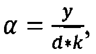
[0019] In the before mentioned embodiment it is preferred that the opening has an inner diameter, especially being smaller than the maximum inner diameter of the interior space, and/or has at least partly a conical cross sectional shape, especially the inner diameter of the opening is about 70% to 90%, more preferred about 75% to 85% and most preferred about 80% of the inner diameter of the interior space, the opening has a cone angle of 20° to 40°, preferably 25° to 35°, most preferred 33,5° with respect to the first rotational axis, the opening has a cone length of 10% to 50%, preferably 20% to 40%, most preferred about 30% of the height of the centrifuge element, especially a cone length of about 120mm to 200mm, more preferred of about 140mm to 180mm and most preferred of about 160mm, especially when the inner diameter (D) of the interior space (15a, 15b) is about 1200mm, and/or the supply means is inclined by an angle with respect to a horizontal axis and/or a plane of the opening, wherein the angle fulfills the relationship
with y being the height of the centrifuge element, d being the inner diameter of the opening and k being a constant in a range of 0,83 to 0,91, more preferred 0,85 to 0,89 and most preferred of about 0,87.
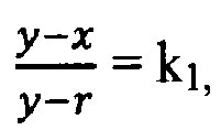
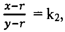
[0020] Furthermore it is proposed that the centrifuge element comprises at least one bottom wall, located especially opposite to the opening, and at least one, especially cylindrical, elliptical and/or circular side wall, wherein preferably above the bottom wall at least one, especially at least partly interchangeable, bottom plate may be located and wherein preferably the corner between the bottom wall and/or the bottom plate on the one side and the side wall on the other side is at least partly rounded, especially with a radius, preferably a radius of about 5% to 15%, more preferred 7,5% to 12,5%, most preferred about 10% of the inner diameter of the interior space and/or of about 100mm to 150mm, most preferred 120mm, and/or the cone length, the height of the centrifuge element and the radius fulfill the relationship
with k1 being 0,3 to 0,5, more preferred 0,35 to 0,45 and most preferred about 0,4, and/or
with k2 being 0,5 to 0,7, more preferred 0,55 to 0,65 and most preferred about 0,6.
[0021] For the before described embodiment it is furthermore proposed that the interchangeable bottom plates have different shapes, and or surface properties, especially different non-sticking properties, comprise different materials, especially having different softness and/or flexibility properties, and/or comprise different apertures for dumping fluids extracted out of the food product by centrifuging.
[0022] The inventive device may further be characterized in that the centrifuge element can be further tumbled around a third rotational axis, especially being mainly perpendicular to the first rotational axis, being mainly parallel to the second rotational axis, running at least partly through the interior space, being located between the bottom wall and/or the bottom plate and the opening, preferably about 13mm, especially when the inner diameter (D) of the interior space (15a, 15b) is about 1200mm, 2% to 3%, more preferred 2,5% to 3,5%, most preferred about 4% of the height of the centrifuge element and/or 5% to 50%, more preferred 7,5% to 30%, most preferred about 10% of the radius of the corner above the bottom wall and/or the bottom plate, and/or running between the side walls and/or intersecting the first rotational axis, especially to transfer the centrifuge element from the filling position and/or the centrifuging position to the discharging position or vice versa.
[0023] An advantageous embodiment may be characterized in that in the area of the bottom wall, the bottom plate, the side wall and/or the corner at least partly a layer of a material being softer than the material of the bottom wall the bottom plate and/or the side wall is located, especially being provided as a cover of the bottom wall, the bottom plate, the side wall and/or the corner.
[0024] An inventive device may further be characterized by at least one discharge means, wherein the food product is transferrable, especially in the discharging position of the centrifuge element, from the interior space to the discharge means, preferably by tumbling the centrifuge element around the third rotational axis, and/or the food product is conveyable by the discharge means to a food product output of the device.
[0025] For the before described embodiment is preferred that by the discharge means the food product transferred from different centrifuge elements is conveyable to one output of the device, wherein preferably the discharge means comprises at least two, preferably a plurality of, collecting means by which the food product is conveyed to the output and/or is conveyed to an intermediate element conveying the food product to the output.
[0026] Furthermore it is proposed that at least one air lock device and/or at least one second valve means, especially comprising at least one rotary valve and/or rotary air lock, through which the food product is conveyed to the output, wherein especially the food product is conveyable by the collecting means and/or the intermediate element to the second valve means and/ or into the air lock device, preferably through an air lock entrance, and/or the food product is conveyable by at least one air lock conveyance element and/or the second valve means to an air lock exit, especially representing the output of the device, and/or onto a product output device.
[0027] Another embodiment of an inventive device may be characterized in that the conveyance means, especially the supply means and/or the dividing element, the fryer conveyance device, the product providing means, the discharge means, the collecting means, the intermediate element, the air lock conveyance element and/or the product output device comprise(s) at least one conveyor belt, at least one conduit, at least one chute, at least one slide, at least one wire mesh belt and/or at least one ramp.
[0028] Finally it is proposed for a device that the device is at least partly housed within a casing, especially a pressure tank, in which vacuum conditions may be provided.
[0030] The sliding height is especially in the order of not more than 3 times, more preferably not more than 2 times, most preferred not more than 1,5 times of an average length, especially a maximum elongation, of the food product and/or maximum velocity is
more preferred
and most preferred
[0031] Alternatively or additionally the method can be characterized in that the food product is placed by the conveyance means close to a side wall of the centrifuge element and/or a corner of the side wall with a bottom wall and/or a bottom plate, before and/or during the conveyance of the food product to the centrifuge element the conveyance means is at least partly inserted into the interior space and/or during or after the conveyance of the food product to the centrifuge element the conveyance means is at least partly extricated out of the interior space and/or the food product is placed onto an already existing layer of food product within the centrifuge element.
[0032] For the method it is further proposed that at least one supply means of the conveyance means is at least partly moved, especially hinged around a second rotational axis into or out of the interior space and/or a length of the supply means is, especially telescopically, altered.
[0033] A preferred embodiment of the method can be characterized in that the food product is conveyed by conveyance means, especially the supply means to at least two, preferably a plurality of, centrifuge elements, wherein the food product is conveyed alternatively to one of the centrifuge elements, especially the supply means is alternatively positioned at least partly in one of the centrifuge elements and/or is actuated in reverse directions, and/or the food product is conveyed by at least one dividing element of the conveyance means, especially by reverse direction actuation of the dividing element to at least two, especially a plurality of supply means, wherein via each of the supply means the food product is conveyed to a respective centrifuge element to which the supply means is attributed.
[0034] The before described embodiment may be characterized in that the centrifuge element is spun with a first speed around the first rotational axis to extract liquid out of the food product, wherein especially during the food product is conveyed to a first centrifuge element, especially when the supply means is located at least partly within the interior space of the first centrifuge element, at least one second centrifuge element is spun with the first speed around its first rotational axis, preferably with the supply means being located outside the interior space of the second centrifuge element, and/or the second centrifuge element is in or is brought into a discharging position, wherein especially the acceleration to the first speed and/or deceleration from the first speed is controlled to reduce relative movement between the food product and the centrifuge element and/or to reduce relative movement of single pieces of the food product relative to each other.
[0035] For the before described embodiment it is further proposed that the conveyance means is positioned within the interior space at least temporarily such that the food product is slided in the corner of the centrifuge element formed between a bottom wall and/or a bottom plate on the one hand and a side wall of the centrifuge element on the other hand and/or that the sliding height (hd,db) of the food product from the conveyance means, especially the supply means, is minimized, and/or that at least temporarily the centrifuge element is rotated with a second speed, being smaller than the first speed, around the first rotational axis, especially that during the filling of the food product into the centrifuge element the centrifuge element is rotated by 360° around the first rotational axis and/or by more than 360° around the first rotational axis, preferably such that the food product is placed onto the already existing layer of food product within the centrifuge element.
[0036] Another embodiment of the method may be characterized in that the centrifuge element is hold in or brought into a filling position before and/or when the food product is conveyed to the centrifuge element, is hold in or is brought into a centrifuging position when and/or before the centrifuge element is spun with the first speed and is hold in or brought into a discharging position to discharge the food product out of the centrifuge element, wherein in the filling position and in the centrifuging position an opening of the centrifuge element is oriented upwards and that the centrifuge element is tumbled around a third rotational axis to transfer the centrifuge element from the filling position or centrifuging position into the discharging position or from the discharging position into the filling position or centrifuging position, wherein the second speed, a third speed around the third axis, an acceleration to the second speed and/or to the third speed and/or a deceleration from the second speed and/or from the third speed, a speed of at least one discharge means and/or a speed of the conveyance means is/are controlled such that internal forces within a food product layer are minimized and/or such that a sliding height of the food product is minimized.
[0037] For the before described embodiment it is preferred that the food product is discharged especially via the opening of the centrifuge element, to the discharge means and/or the food product is conveyed by the discharge means to the output of the device, wherein especially the food product is conveyed from the centrifuge element to the discharge means, from one element of the discharge means to another element of the discharge means and/or from the discharge means to the output by a sliding movement and/or with a minimized drop height, especially a drop height below 150mm, more preferred a drop height below 100mm.
[0038] The invention furthermore proposes that the food product is conveyed from different centrifuge elements, especially the first centrifuge element and the second centrifuge element, preferably by the discharge means to the output of the device, wherein especially the discharge means comprises at least two, preferably a plurality of, collecting means by which the food product is conveyed to the output or is conveyed to at least one intermediate element conveying the food product to the output.
[0039] Finally an inventive method may be characterized in that the food product is provided as a fried product to the conveyance means via at least one fryer conveyance device and/or as a raw material and/or non-fried material to the conveyance means via at least one product providing means.
[0040] Thus the claimed subject-matter is based on the astonishing perception that a method and a device for centrifuging of a food product, especially fried snack food products, with the aim to separate liquid substances from solids under vacuum and/or atmospheric conditions, wherein the food products are sensitive for breakage, can be provided that allows a lower breakage ratio by reducing mechanical impacts on the product during filling, centrifuging, emptying and discharging of the food product into and out of the centrifuge element. According to the invention this reduction of the product impact is achieved by ensuring that the food product is transferred from one element to another element mainly by a sliding movement, at least with reduced dropping heights, especially the dropping height of the product into the centrifuge element, especially a centrifuge basket. In the sense of the invention a sliding movement is distinguished from other movements, especially a dropping, by a velocity of the product in the movement of an impact on the another element. A sliding movement is especially given when the velocity during impact is below
better below
and at the best below
A sliding movement is especially given independent from these criteria or in addition to the before described criteria when the product does not loose contact to the means conveying and/or transferring the product. More precisely this sliding movement and reduction of the sliding height and the velocity during impact is reached in that respective transportation devices, like a conveyance means, are adapted to each other, especially with respect to a transportation speed and/or a relative arrangement to each other. Especially the conveyance means, preferably a feed belt, is movable such that it is at least partly insertable into or extricable out of an interior space of the centrifuge element, especially a centrifuge basket.
[0041] Preferably an increased diameter of the centrifuge element in comparison to the ones known in the state of the art allows to insert the conveyance means into the interior space, which makes it possible to fill the centrifuge element without or with reduced dropping and/or sliding heights.
[0042] In case the conveyance means is realized by a feed belt the feed belt might be a equipped with a hinged belt part. For sensitive handling of the food product during the distributing into the centrifuge basket the hinged belt part may be lowered into the interior space of the centrifuge element. In such a filling position of the feed belt the position of the end of the feed belt and the angle of the feed belt ensure that the product has a minimized sliding height and slides the product close to a side wall or a corner of the basket. Especially the sliding height and/or dropping height of the product may be minimized below 150mm. By reducing the sliding height the mechanical impact is reduced. Furthermore by filling the fried product to this part of the basket, during the later spinning of the centrifuge element a relative movement of the food product with respect to the centrifuge element as well as a relative movement of single elements of the food product with respect to each other, especially in a radial direction of the spinning movement, is reduced. To furthermore reduce the mechanical impact and stresses during spinning, especially during an acceleration of the centrifuge element, the centrifuge element is rotated during the filling. The rotation might be such that the centrifuge element makes only one rotation of 360° during the filling to reduce a thickness of the product layer and to soften the sliding. The rotation might alternatively be such that a rotation of more than 360° is carried out during the filling. That means that by the rotation of the centrifuge element it is furthermore reached that following food product items are sliding not the whole distance into the centrifuge element but have a reduced sliding height onto other food product items what furthermore reduces the sliding height for these following food items and thus reduces the risk of breakage. Thus during filling the food product is placed onto an already existing layer of food product within the centrifuge element, or in other words the product might be placed during filling product on product. This allows to reduce the dropping height even more, for example below 100mm, which further reduces product breakage. For establishment of the product on product layer a bottom plate of the centrifuge element may be mounted such that, at least during filling, the product being directly located on it will stay in its position. By this stapling also the effectiveness of the centrifuging is increased as liquid can leave the food items more easily. After the filling of the centrifuge the hinged belt part will be lifted out of the basket and the centrifuge starts to spin.
[0043] Especially by this measure the impact on the food product is reduced by reducing a sliding height of the product entering the centrifuge basket; the position of the product in the corner of the basket leads to a reduction of product movement during spinning, especially the acceleration of the centrifuge basket.
[0044] Furthermore before filling the food product into the centrifuge element the food product can be handled, especially transported such that mainly a sliding motion is caused when transferring it from one element of the device to another element. This also decreases the impact on the product, at least reduces a respective sliding height.
[0045] By controlling the feed belt angle and also the conveyance speed of the feed belt the impact of the product sliding into the basket can also be controlled and especially minimized, especially by reducing the sliding height and the speed with which the products falls into the basket; and also a carefully lay down of the products during the filling is reached by positioning the food product within the centrifuge element such that it creates a product layer that is similar to the form of the one that is created by centrifuging to create an optimum relation between layer height and the layer thickness to also reduce the stresses onto the food product during the spinning/centrifuging process.
[0046] According to the invention the conveyance means is especially not restricted to a feed belt but might also incorporate a slide or chute to transport the product into the centrifuge element. When using a belt it is preferred that the belt is provided with a wire mesh belt. These belts have the tendency to damp an impact when the product drops onto the belt. Due to this "spring" function of the belt the product breakage is further reduced.
[0047] To reduce impacts onto the product during the transfer to the conveyance means or from one element of the conveyance means to another the speed of the conveyance means and the elements of the conveyance means are adapted to the speed of a feeding means, like a fryer belt. This allows to locate the elements of the conveyance means or the conveyance means and the feeding means close to each other to allow a sliding movement, at least a reduced sliding height of the food product.
[0048] Furthermore it was found that the discharging of the food product into a sluice chamber by using a bottom valve in the centrifuge element and furthermore the discharging of the food product out of the sluice chamber using also another valve also leads to an increased impact onto the food product and thus an increased breakage.
[0049] Thus, in addition to the above measures regarding the transport of the food products to the centrifuge element or the filling of the food product into the centrifuge element, which might be realized independently from each other, in addition or alternatively to these measures further provisions can be provided to reduce the breakage ratio of the food product during the discharge of the food product out of the centrifuge element.
[0050] This reduction is achieved by tumbling the centrifuge element around a third rotational axis that is especially perpendicular to the first rotational axis when the centrifuge element is spun for centrifuging. This allows especially the centrifuge element to have only one single opening. This single opening is used for filling as well as emptying. Emptying is especially achieved when tumbling the centrifuge element around the third axis. This avoids the necessity of a second opening, especially a bottom valve as known in the state of the art. This rotational axis for tumbling furthermore runs preferably through the interior space of the centrifuge element and allows a discharging of the food product out of the centrifuge element, especially via the opening through which the food products are fed into the centrifuge element on to a discharge means, preferably in form of a collecting belt. Also for discharging the geometry of the centrifuge element and the tumbling speed is adapted to reach a reduced sliding height, especially to avoid a dropping of the food product by sliding the food product. Thus, during filling and spinning/centrifuging the centrifuge element, especially in form of the centrifuge basket, remains in a vertical filling or centrifuging/spinning position, that means that an opening of the centrifuge element is located on the upper side of the centrifuge element. After the centrifuge element has stopped centrifuging the whole centrifuge element tumbles to empty the products onto a transport or collecting belt. Especially by controlling an acceleration and deceleration speed of the centrifuge element during the tumbling movement internal forces in the product layer are reduced and thus an additional product breakage is prevented. Also for sensitive discharge of the products the tumbling speed is controlled. In this way the food product will be collected on a connecting or transport belt underneath the centrifuge element.
[0051] Due to the position of the rotational axis for the tumbling also the sliding height of the food product during this discharging is minimized. This is furthermore supported by the fact that an opening of the centrifuge element might by cone shaped as explained later.
[0052] Especially this cone shape opening allows to ensure a sliding motion of the food product within and out of the centrifuge element instead of a dropping out of the centrifuge element. Especially by the tumbling of the centrifuge element in comparison to the opening of a bottom valve the mechanical impact onto the food product is minimized as already mentioned above.
[0053] Surprisingly it has been found that no additional space within the room in which the centrifuge element is located, especially a vacuum tank is, needed in comparison to the state of the art devices. Especially by adapting the geometry of the centrifuge element and the location of the rotational axis for the tumbling as well as the by the respective cross sectional shape of the centrifuge element the needed space can be minimized by simultaneously minimizing a distance between the centrifuge element, especially the opening, and the discharge means.
[0054] The reduction of an impact on the food product during the filling into the centrifuge element as well as during the discharge of the food product out of the centrifuge element is, as already mentioned, furthermore supported by the form of the centrifuge element. Especially the centrifuge element has round corners and a reduced opening diameter, especially a cone shaped opening, to prevent uncontrolled discharge of the product. Due to the form of the centrifuge element and/or its tumbling around the third rotational axis dropping heights onto the conveyance means, especially the discharging means, can be reduced below 100mm. This further reduces product breakage. Especially by the conical opening the discharge speed and sliding height of the product onto the discharging means, like the collecting belts, can be controlled and minimized. Furthermore by providing a bottom plate of the centrifuge element that might be replaceable and/or might be made of a softer material in comparison to the remaining parts of the centrifuge element, the mechanical impact onto the food product during filling and discharging might also be reduced. Especially, the bottom plate can be replaced by a bottom plate with different shapes, and different softness properties or non-sticking properties materials.
[0055] By providing respective openings within the bottom plate and by providing a space beneath the bottom plate fluid which is leaving the product during spinning can be collected in the centrifuge element housing and will be distributed back into the frying process, however the centrifuge element is designed in such a way that during tumbling for the discharge the oil remains in the space.
[0056] Further, by providing respective geometric forms of the centrifuge element, especially round corners, the pressure in the product layer can be reduced during spinning. This pressure is additionally reducible by means of soft materials comprised by or located on the bottom plate.
[0057] Furthermore not only by the filling and discharging of the food product into or out of the centrifuge element the risk of a product breakage might by reduced. To especially reduce sliding heights of the food products onto or from the conveyance means respective measures can be taken. For example a feed belt of the conveyance means, that conveys the products to the centrifuge element maybe positioned directly underneath a discharge of a fryer to reduce transfer times between frying process and centrifuging but also to allow, as explained above, a sliding motion of the food product in comparison to a dropping.. Thus by adapting the position of the conveyance means, sliding height and the speed of the belt the likelihood of breakage might also be reduced. Furthermore the speed of the discharge means, especially of a collecting belt or intermediate belt after discharging the food product out of the centrifuge element can be controlled to ensure a sliding motion of the food product, at least to lower sliding heights during emptying of the centrifugal element.
[0058] Usually after emptying the centrifugal element the food product is distributed to an intermediate buffer, especially in form of the intermediate or a buffer belt. From the intermediate vacuum buffer belt the product is than distributed on to product discharge locks (sluices). In the sluice conditions might be revealed and the product will be distributed out of the sluices. Also by adapting the speed and geometry of the buffer as well as the sluices drop heights can be minimized and thus the likelihood of breakage can be reduced.
[0059] In a preferred embodiment the food product is collected on the conveyance means, than distributed by choosing a direction of travel of the conveyance means or by using respective separate supplying means to which the conveyance means conveys the food product, to allow the installation of parallel centrifuge elements, for example two parallel centrifuge elements. In this configuration it is especially proposed that always one centrifuge element is in its filling position while the other centrifuge element spins/centrifuges. The filling of the centrifuge element stops after the second centrifuge is back in its filling position and then the feeding direction conveyance means might be switched into an opposite direction to start filling of the other centrifuge element. This process allows to adapt the filling degree of the food product in the centrifuge elements to an optimum value such that the mechanical internal stresses within the food product are minimized further reducing the breakage ratio.
[0060] Further measures to reduce the breakage can also be taken, for example the tumbling speed and tumbling acceleration might be controlled to prevent additional product breakage by ensured sliding of the product during tumbling and discharge on the discharge means. The actuator of the centrifuge element, especially to accomplish a rotation around the first rotational axis, is preferably equipped with an application controller to control a (slower) startup, especially at a speed lower than the first speed, of the centrifuge element and a (slower) stop of the centrifuge. By this abrupt starts and stops are eliminated and product breakage as a result of the mechanical impact due to relatice movement of the product and the centrifuge is reduced. Also the acceleration and deceleration of the centrifuge element for spinning can be controlled beside the filling degree to reduce internal forces in the food product layer which might result in additional breakage. When filling the centrifuge element also a predefined orientation of the food product can be reached by a control of the movement of the centrifuge element as well as the part of the conveyance means that is inserted into the interior space of the centrifuge element.
[0061] Especially during the filling the centrifuge element a rotational speed of the centrifuge element can be controlled such that by one turn of the centrifuge element a sliding of the food product can be softened and a product impact can be reduced by making use of an already existing product layer within the centrifuge element.
[0062] Also the spinning speed during centrifuging can be controlled to adjust the applied speed forces to optimize the centrifuging process, that means to optimize a force for maximum extraction of liquid out of the food product and to simultaneously minimize a breakage of the food product.
[0063] In addition to the measures, described above, the environment, in which centrifuging is carried out can further be controlled, especially by controlling the environmental temperature and humidity, to reduce a breakage ratio. For example, steam, saturated or supper heated, may be injected into the centrifuge element or a heating device like a infrared heater might be positioned in the centrifuge element.
[0064] Also it might be an advantage to tumble the centrifuge element by 360° to discharge the food product to optimize the discharge process especially to reduce the time during which the centrifuge is not spinning or not filled.
[0065] In preferred embodiments the product discharge lock (sluice) can be replaced by an airlock to discharge the product out of the device. As this allows the use of transportation elements like additional belts to convey the food product to the output may be used also reducing the risk of breakage.
[0066] When belts or slides are used to transport the food product different belt types or conveyances types may be used for example to adapt a belt or slide material to specifications of the food product, for example soft materials maybe used to reduce mechanical impacts.
[0067] Further details of the invention will be described in the following specification in which examples of the invention are explained with the help of figures, in which
- Figure 1
- is a schematic view onto a device according to the invention;
- Figure 2a
- is a another view onto the device of figure 1 furthermore showing an airlock device for discharging food products;
- Figure 2b
- is a view comparable to the one shown in figure 2a onto an alternative device comprising respective rotary air lock devices;
- Figures 3a to 3d
- are schematic views onto a part of the device showing different positions of the device during a filling of the centrifuge element;
- Figure 4
- is a perspective view onto a part of the device similar to figures 3a to 3d during a spinning of the food product;
- Figures 5a to 5c
- are views onto the centrifuge element in different positions of the centrifuge element during a discharging of the food products out of the centrifuges element;
- Figure 6
- is a perspective view onto the centrifuge element of the device of figures 1 to 5c in form of a centrifuge basket;
- Figure 7
- is a detailed view onto the cutout A in figure 6;
- Figures 8a to 8b
- are schematic views onto the centrifuge element showing different geometrical dimensions of the same; and
- Figure 9a and 9b
- are schematic views onto the different elements of the device showing respective geometrical dimensions;
[0068] Figure 1 shows a view onto a centrifuge device 1 according to the invention. As shown in figure 1 the centrifuge device 1 comprises a casing in form of a pressure tank 3. Within the pressure tank 3 vacuum conditions can be established, especially a pressure below atmospheric pressure up to 10 mbar, preferably in a range of 20 to 200 mbar may be generated. Into the pressure tank 3 a fryer conveyance device in form of a fryer belt 5 is reaching. As explained later in alternative embodiments the food product might be provided as a fried product but also in form of a non-fried and/or raw material by other devices, like a product providing means and/or a rotary valve.
[0069] The fryer belt 5 conveys food products, that have undergone a frying step before, to the centrifuge device 1. The centrifuge device 1 furthermore comprises a conveyance means in form of a dividing belt 7. As explained later the dividing belt 7 is separated in different sections wherein a section 7a fulfills the function of a dividing element whereas the sections 7b represent respective supply means. By reverse actuation of the dividing belt 7 the food products provided by the fryer belt 5 can be conveyed to respective centrifuge elements in form of centrifuge baskets 9a and 9b.
[0070] As explained also later, the centrifuge baskets 9a, 9b may be spun around respective first rotational axis 11a and 11b respectively. By spinning the centrifuge baskets 9a and 9b an amount of liquid, especially fat or water, contained in or located on a surface of the food product is reduced by separating the liquid and the solid components of the food product. As also explained later the dividing belt 7 is constructed such that the supply means 7b can be hinged around a second rotational axis 13 relative to the dividing element 7a to allow to insert and to extricate the supply means 7b into and out of the interior spaces 15a, 15b of the centrifuge baskets 9a and 9b. Furthermore it is shown in figure 1 that the centrifuge baskets 9a and 9b can furthermore be tumbled around a third rotational axis 17a, 17b. As shown for centrifuge basket 9b the centrifuge basket 9b can be tumbled around the third rotational axis 17a, 17b to allow a discharging of food products out of the centrifuge basket 9b onto a discharge means, more precisely a collecting means of the discharge means, in form of a collecting belt 19b. Via the collecting belts 19a, 19b food products can be conveyed from the centrifuge elements to a food product output or intermediate element in form of an intermediate belt 21.
[0071] In figure 2a the respective components of the centrifuge device 1 are shown from a different perspective. As can be taken from figure 2a the centrifuge device 1 is connected via the intermediate belt 21 to an airlock 23. Both, the airlock 23 and the pressure tank 3, are connected to a vacuum system 25 to establish vacuum conditions within the airlock 23 and the pressure tank 3. Within the airlock 23 a further air lock conveyance element in form of an airlock belt 27 is located. The food product is conveyed via the intermediate belt 21 through an air lock entrance in form of an opening 29 onto the airlock belt 27 and, after closing the opening 29, another opening 31 of the airlock 23 representing an air lock exit is opened to discharge the food product from the airlock belt 27 onto a product output belt 33.
[0072] Thus the centrifuge device 1 allows to fill respective centrifuge elements 9a, 9b with a food product, to centrifuge the food product and to discharge it out of the centrifuge elements 9a, 9b to an output of the device 3.
[0073] In figure 2b another centrifuge device 1' according to the invention is shown in a perspective view comparable to figure 2a. The components of centrifuge device 1' that are identical to the ones of centrifuge device 1 have the same reference numbers. The centrifuge device 1' differs from the centrifuge device 1 by different product infeeds and discharges. The food product is provided to the dividing belt 7, especially dividing element 7a, via a feed means in form of a feed belt 6'. From outside the pressure tank 3 the food product is provided to the feed belt 6' via a first valve means in form of a rotary air lock comprising a rotary valve 4' being connected to the vacuum system 25. The first valve means 4' allows to provide the food product to the centrifuge device 1' irrespective of the location of a pre-treatment device, like a fryer. Via the first valve means 4' all kinds of food products, fried products, pre-fried products but also raw food products, may be provided. In line with the invention the position of the first valve means 4' is chosen such that the food product is transferred to the feed belt 6' by a sliding motion.
[0074] In contrast to the centrifuge device 1, centrifuge device 1' furthermore comprises a different air lock 23' at the discharge side of the centrifuge device 1'. The air lock 23' is also formed in form a rotary air lock comprising a rotary valve 24'. Also the rotary valve 24' is connected to the vacuum system 25 and furthermore the rotary valve 24' is located with respect to the intermediate belt 21 as well as the product output belt 33 such that the sliding heights are chosen so that the food product is not dropping but sliding form the intermediate belt 21 into the rotary valve 24' and also slides out of the rotary valve 24' onto the product output belt 33.
[0075] In the following, the respective steps of the centrifuging carried out by centrifuge device 1 or 1' are described with the help of figures 3a to 5c, especially with the help of figures 3a to 3b the filling of the centrifuge element is explained, with the help of figure 4 the centrifuging is explained and with the help of figures of 5a to 5c the discharge of the food product out of the centrifuge element 9b is explained.
[0076] In figure 3a the centrifuge device 1 is shown in the starting position of the centrifuge element 9b. The centrifuge element 9b is in a filling position and the supply means 7b is located outside the interior space 15b of the centrifuge basket 9b. By hinging the supply means 7b around the rotational axiss 13 the supply means 7b is brought into the position shown in figure 3b. In this position the supply means 7b is at least partly located within the interior space 15b. This leads to the effect that food products that are provided by the fryer belt 5 are directly conveyed via the dividing belt 7 to the centrifuge element 9b, thus reducing a transfer time between the fry process and the centrifuging process. By bringing the supply means into the position shown in figure 3b, by a respective rotation of the supply means 7b relative to the dividing element 7a and also relative to the centrifuge basket 9b the food product is conveyed into the centrifuge basket 9b such that only a minimum sliding height for the food product is existing. The food product is especially not dropping but only sliding into the centrifuge basket 9b. Furthermore, the food product is positioned in a corner 35 of the centrifuge basket 9b formed between a bottom wall 37 and a side wall 39, especially close to the side wall 39. Thus a later movement of the food product in radial direction of axis 11b is minimized to avoid impacts onto the product that might lead to a breakage.
[0077] During the conveying of food products into the centrifuge basket 9b the centrifuge basket 9b is turned around the first rotational axis 11b such that the centrifuge basket 9b makes one rotation of 360°. It is also possible to move the supply means 7b around the rotational axis 13 to lift it at least a small amount out of the interior space 15b to allow that additional food products slide onto an existing product layer to soften the sliding.
[0078] The product distribution into the centrifuge basket 9b by rotating the same around the first rotational axis is shown in figure 3c by respective arrows. After filling the centrifuge basket 9b, especially in a way that a product layer is produced that is similar to the one created by centrifuge forces, to reduce internal stresses in the food product the supply means 7b is lifted out of the interior space 15b as shown in figure 3d. This lifting especially takes place after a direction of movement of the dividing belt, especially the dividing element 7a and/or the supply means 7b, has been reversed.
[0079] As shown in figure 4 by a respective arrow around axis 11b the centrifuge basket 9b is spun around the first rotational axis 11b when the supply means 7b is in a position outside the interior space 15b. By spinning/centrifuging the food product, the liquid or fat located on the product will be separated and thus their content on the food product is reduced.
[0080] After the centrifuging of the food product the food product is discharged out of the centrifuge basket 9b as shown in figures 5a to 5c.
[0081] By tumbling the centrifuge basket 9b around a third rotational axis 17b the food product slides onto the collecting belt 19b. As the third rotational axis 17b is located within the interior space 15b a minimum space for the tumbling of the centrifuge basket 9b is necessary. Further by the cone shape from of the basket opening the edge of the opening is located close to the collecting belt 19b allowing a sliding instead of a dropping of the food product onto the collecting belt 19b. As shown in figure 5b the food product is than conveyed via the collecting belt 19b onto an intermediate belt 21 and after discharging of the food product the centrifuge basket 9b is returned into the filling position as shown in figure 5c.
[0082] Also by this ratio it is possible to fill in the food product such that the generated product layer is very similar to the layer formed during centrifuging thus leading to reduced stresses within the product layer.
[0083] To additionally reduce the impact on the food product when the food product is filled into the centrifuge element or is discharged out of the centrifuge element, the centrifuge elements have respective geometrical properties. These properties are now explained with the help of figures 6 to 8b.
[0084] As shown in figure 6 the centrifuge basket 9b comprises a corner 35 that connects a bottom wall 37 and a side wall 39. As the corner 35 is rounded, during a centrifuge rotation of the centrifuge basket stresses onto the food product are avoided. As furthermore shown in figure 6 the side wall 39 extends into a cone shaped opening 41 of the centrifuge basket 9b.
[0085] As especially shown in figure 7 on the bottom wall 37 a bottom plate 43 made of a soft material is positioned. A flexible connection of the bottom plate to the bottom wall 37 of the centrifuge basket 9b is provided. The soft material ensures that the impact on the food product is additionally reduced when the food product is falling into the centrifuge basket 9b and the flexible connection reduces the transfer of thrusts onto the food product for example due to an imbalance of the centrifuge element. Also it can be seen that in the bottom wall 37 respective openings are formed that allow that the separated liquid is fed back, for example fat goes back into a fryer. However, when tumbling around the third axis of the centrifuge basket 9b, it is secured that the extracted liquid will not flow back into the interior space 15b what may lead to an unwanted moisten of the food product by the liquid flowing back onto the surface of the food product. This is reached by predefined positioning of respective openings in the bottom wall, especially close to the axis 11b but not close to the side wall 39.
[0086] In figures 8a and 8b respective geometrical dimensions of a basket 9b are shown. It was found that by the following geometrical dimensions, especially special relationships between the geometrical dimensions, the sliding motion of the food product can be achieved. The food basket 9b might have a diameter D of about 1200 mm, a height of the side wall x of 350 mm and a total height y of 510 mm. The corner 35 might have a radius r of 120 mm. This radius of the corner has been found to allow the most smooth handling/motion of the food product during filling and discharging of the centrifuge element, especially allowing a sliding motion. This radius has furthermore be found to be a good fit for any food product, especially any geometry and geometric dimensions of food product, and also any size of the centrifuge element, especially inner diameter of an interior space of the centrifuge element. However the ratio of the height of the side wall of 350 mm and the radius r of 120 mm of about 1/3 has been found to lead to a best reduction of stresses in the food product during centrifuging, especially with a inner diameter D of 1200mm.
[0087] It was especially found that for a gentle handling of the food product, especially by assuring a sliding of the food product, the relationship between the height x, the height y and the radius should be chosen such that the ratio
should be in a range of 50% to 70% , more preferably 55% to 65% and most preferred about 60% and/or the ratio
should be in the range of about 30% to 50%, more preferred 35% to 45% and most preferred about 40%.
[0088] The angle ϕ of the cone shape opening 41 might be 33,5°. As shown in figure 8b when discharging the food product out of the centrifuge basket 9b the centrifuge basket is rotated around the third axis that is located in a distance c of 13 mm from the bottom wall 37. It was found that for a smooth discharging of the product, especially to reduce a distance between the centrifuge basket 9b and the collecting belt 19b to reach a sliding motion of the food product and to limit the velocity when the product touches the collecting belt 19b, the geometry of the corners of the basket should be chosen such that the inner diameter d of the opening 41 is preferably in a range of 70% to 90% of the diameter D, more preferred in a range of 75% to 85% of D and most preferred about 80%, so that the angle ϕ, that fulfills the relationship tan ϕ =
allows to rotate the basket around the axis being located in a distance c of 5% to 50% of r, preferred 7,5% to 30% of r and most preferred about 10% of r, without a contact between the basket 9b, especially the corners of basket 9b, with the collecting belt 19b.
[0089] For the same reason to avoid a contact between the basket 9b and the collecting belt 19b it is preferred that the radius r is about 5% to 15% of the diameter D, more preferred 7,5% to 12,5% of the diameter D and most preferred about 10% of D.
[0090] The combination of the height y of the basket, the cone shape angle ϕ, the side wall height x and the position of the third rotational axis, especially the distance from the bottom wall, allows that an edge of the opening 41 is located very close to the collecting belt 19b such that the food product slides out the interior space 15b onto the collecting belt 19b with a limited velocity when the centrifuge basket 9b is in its discharging position. For a discharge of the food product the centrifuge basket might be rotated around the third rotational axis 17b by an angle P of between 150 ° to 180 °, preferably 155°. It is also possible that the centrifuge basket 9b is than rotated by a total of 360° back into the filling position.
[0091] When spinning the centrifuge basket 9b around the fest axis 11b a force of 35 g to 100 g, preferably 60g, is generated, depending on the product properties. When discharging the food product out of the centrifuge basket the centrifuge basket might be tumbled with a speed of 0,21 radiant pro second around the angle β.
[0092] In such a centrifuge a total batch weight input of 8 kg to 18 kg, especially 10 kg can be processed leading to filling degree of the centrifuge basket of between 4 % to 9 %. Examples for food products might be vacuum dried potato sticks having a product cut size of 8,7 mm x 8,7 mm and with a product a length of between 40 to 85 mm. The input moisture content enclosed within the food product might be between 0,8 and 1,2 % of weight and might have a total fat content enclosed within the food product and located on the food product surface of about between 58 % and 62 % of weight before centrifuging, for example a fat content of 60 %. Depending on the frying process the temperature of the food product might be in the range of 100 °C to 130 °C ° most likely 120 °C.
[0093] After centrifuging the food product might have a fat content of 35 to 45 %, especially 40% of fat. This value may especially be achieved when a working pressure of 30 to 50 mbar especially 30 mbar is existing within the pressure tank 3.
[0094] For conveying the food product into the centrifuge basket the dividing belt having a length of ldb1 for the dividing element and a length of ldb2 for the supply means might run with a speed of about 0,035 to 0,07 m/s, especially 0,05 m/s whereas the centrifuge basket is turned with a speed of 0,9 to 0,46, especially 0,5 rpm during the filling of the food product into the centrifuge basket.
[0095] Preferably the angle of the supply means to relative to a horizontal direction is between 30 ° and 40 °, for example 36 ° during filling process. This infeed angle is especially shown as α in figure 9a and secures that the food product slides and not drops into the centrifuge basket 9b. It has been found that this sliding motion may be reached when the angle α fulfills the relationship
with the constant k being in the range of 0,82 to 0,91 more preferred 0,85 to 0,89 and most preferred about 0,87.
[0096] Furthermore, in figures 9a and 9b examples for the slide heights are shown. The sliding height hd,fb from the fryer belt 5 to the dividing belt 7a might be for example 100 mm whereas the next sliding height hd,db from the diving belt, especially the supply means 7b, into the centrifuge basket might be 150 mm.
[0097] After centrifuging and tumbling of the centrifuge basket 9b around axis 17b the food product has to slide a sliding height hd,c from the centrifuge basket 9b to the connecting belt of 120 mm, whereas the sliding height hd,ib from the collection belt 19a to the intermediate belt 21 might be 80 mm. In the airlock 23 the food product overcomes than sliding a height hd,ab from the intermediate belt to the airlock belt 27 or the rotary valve 24' of centrifuge device 1' (not shown in figure 9a) that might be 135 mm whereas the maximum sliding height hd,cu from the air lock belt 27 or the rotary valve 24' to the product output belt 33 extending to a customer distribution is about 150 mm. By these geometrical dimensions in combination with respective lengths lab of the airlock belt, lib of the intermediate belt and lcb of the collecting belt, it is secured that the food product does not drop but slides from one element of the centrifuge device to another element, especially the velocity of an impact on the another element is below a maximum velocity so that a total survival index of 91,5 % could be reached in comparison to a survival index of about 54,9 % in the state of the art system. This is especially achieved by choosing the sliding heights in the order of the length of the food product being about 85mm.
[0098] In said state of the art systems the food product has to overcome drop heights that corresponde to the respective sliding heights of for example hd,fb of 150 mm, hd,db of 500 mm, hd,c of 500 mm, hd,cb of 900 mm and hd,cu of 350 mm. As these heights are more than 4 orders higher than a length of the food product of about 85mm such distances lead to a dropping of the food product causing severe impacts onto the food product that result in a high breakage, as more height will result in a higher velocity of the product in the moment of impact. Due to the before described dimensions the velocities in state of the art systems are more than 4 times higher.
[0099] The breakage ratio is furthermore decreased by the provision that during the centrifuging the centrifuge element is accelerated for 5 to 10 seconds, especially 20 seconds, hold at the maximum speed for about 10 to 30 seconds, especially 20 seconds and finally decelerated over a time of 10 to 20 seconds, especially 20 seconds.
[0100] The features disclosed and described in the claims, the specification and the figures might be essential for the claimed invention in the respective embodiments, both when taken separately or when taken in combination with each other.
Reference sign list
[0101]
- 1, 1'
- centrifuge device
- 3
- pressure tank
- 4'
- rotary valve
- 5
- fryer belt
- 6'
- feed belt
- 7
- dividing belt
- 7a
- dividing element
- 7b
- supply means
- 9a, 9b
- centrifuge basket
- 11a, 11b
- rotational axis
- 13
- rotational axis
- 15a, 15b
- interior space
- 17a, 17b
- rotational axis
- 19a, 19b
- collecting belt
- 21
- intermediate belt
- 23, 23'
- airlock
- 24'
- rotary valve
- 25
- vacuum system
- 27
- air lock belt
- 29
- opening
- 31
- opening
- 33
- product output belt
- 35
- corner
- 37
- bottom wall
- 39
- side wall
- 41
- opening
- 43
- bottom plate
- A
- cutout
- D
- diameter
- d
- inner diamter
- x
- height
- y
- height
- y-x
- cone length
- α
- infeed angle
- ϕ
- cone angle
- β
- tumbling angle
- c
- distance
- lab, lib, , lcb, ldb1, ldb2
- length
- hd,ab, hd,ib, hd,db, hd,fb, hd,c
- slide height
- k1, k2, k3
- constant
1. Device (1, 1') for centrifuging at least one food product provided to the device (1,
1') via a feeding (5) means, the device (1, 1') comprises at least one conveyance
means (7, 7a, 7b) and at least one centrifuge element (9a, 9b) having an interior
space (15a, 15b) to receive the food product and being adapted to be spun around a
first rotational axis (11a, 11b), wherein the food product is conveyable into the
internal space (15a, 15b) via the conveyance means (3, 5, 6', 7, 7a, 7b), the conveyance
means comprises a dividing element (7a) and at least one supply means (7b), wherein
the food product is conveyed to the supply means (7b) via the dividing element (7a),
and via the supply means (7b) to the centrifuge element (9a, 9b) and wherein further
the conveyance means (7, 7b) is at least partly insertable into and extricable out
of the interior space (15a, 15b) such that the supply means (7b) is at least partly
positionable within the interior space (15a, 15b) by at least partly moving the supply
means (7b), characterized in that
the supply means (7b) is turnable with respect to the dividing element (7a) around a horizontal second rotational axis (13) such that the supply means (7b) may be lowered into and lifted out of the interior space (15a, 15b).
the supply means (7b) is turnable with respect to the dividing element (7a) around a horizontal second rotational axis (13) such that the supply means (7b) may be lowered into and lifted out of the interior space (15a, 15b).
2. Device according to claim 1, characterized in that
a length of the supply means (7b) is, especially telescopically, alterable.
a length of the supply means (7b) is, especially telescopically, alterable.
3. Device according to claims 1 or 2, characterized by
at least two, preferably a plurality of, centrifuge elements (9a, 9b), wherein the food product is conveyable alternatively to one of the centrifuge elements (9a), especially the supply means (7, 7a, 7b) is alternatively positionable at least partly in one of the centrifuge elements and/or is actuatable in reverse directions.
at least two, preferably a plurality of, centrifuge elements (9a, 9b), wherein the food product is conveyable alternatively to one of the centrifuge elements (9a), especially the supply means (7, 7a, 7b) is alternatively positionable at least partly in one of the centrifuge elements and/or is actuatable in reverse directions.
4. Device according to one of the preceding claims, characterized in that
conveyance means (7) comprises at least one dividing element (7a) to alternatively convey the food product, especially by reverse direction actuation, to at least two, especially a plurality, of supply means (7b), wherein via each of the supply means (7b) the food product is conveyable to a respective centrifuge element (9a, 9b) to which the supply means (7b) is attributed.
conveyance means (7) comprises at least one dividing element (7a) to alternatively convey the food product, especially by reverse direction actuation, to at least two, especially a plurality, of supply means (7b), wherein via each of the supply means (7b) the food product is conveyable to a respective centrifuge element (9a, 9b) to which the supply means (7b) is attributed.
5. Device according to claim 4, characterized in that
the supply means (7b) and the dividing element (7a) are at least partly one-piece.
the supply means (7b) and the dividing element (7a) are at least partly one-piece.
6. Device according to one of the preceding claims, characterized in that
the second rotational axis (13) is perpendicular to the first rotational axis (11a, 11b) and/or the supply means (7b) is turnable via a hinged connection, especially between the supply means (7b) and the dividing element (7a).
the second rotational axis (13) is perpendicular to the first rotational axis (11a, 11b) and/or the supply means (7b) is turnable via a hinged connection, especially between the supply means (7b) and the dividing element (7a).
7. Device according to one of the preceding claims, characterized in that
the feeding means comprises at least one fryer conveyance device (5), at least one product providing means, and/or a first valve means, especially comprising at least one rotary valve (4') and/or rotary air lock for providing the food prodcut to the conveyance means (7, 7a, 7b), and/or the food product is provided to the conveyance means (7, 7a, 7b).
the feeding means comprises at least one fryer conveyance device (5), at least one product providing means, and/or a first valve means, especially comprising at least one rotary valve (4') and/or rotary air lock for providing the food prodcut to the conveyance means (7, 7a, 7b), and/or the food product is provided to the conveyance means (7, 7a, 7b).
8. Device according to one of the preceding claims, characterized in that
the centrifuge element (7a, 7b) comprises at least one opening (41), preferably only one single opening (41), through which the food product is conveyed into and/or conveyed out of the centrifuge element (9a, 9b), wherein preferably in a filling position and/or a centrifuging position of the centrifuge element (9a, 9b) the opening is mainly oriented upwards and/or in a discharging position of the centrifuge element (9a, 9b) mainly oriented downwards.
the centrifuge element (7a, 7b) comprises at least one opening (41), preferably only one single opening (41), through which the food product is conveyed into and/or conveyed out of the centrifuge element (9a, 9b), wherein preferably in a filling position and/or a centrifuging position of the centrifuge element (9a, 9b) the opening is mainly oriented upwards and/or in a discharging position of the centrifuge element (9a, 9b) mainly oriented downwards.
9. Device according to claim 8, characterized in that
the opening (41) has an inner diameter (d), especially being smaller than the maximum inner diameter of the interior space (15a, 15b), and/or has at least partly a conical cross sectional shape, especially the inner diameter of the opening is about 70% to 90%, more preferred about 75% to 85% and most preferred about 80% of the inner diameter (D) of the interior space (15a, 15b), the opening has a cone angle (ϕ) of 20° to 40°, preferably 25° to 35°, most preferred about 33,5° with respect to the first rotational axis (11a, 11b), the opening has a cone length (y-x) of 10% to 50%, preferably 20% to 40%, most preferred about 30% of the height (y) of the centrifuge element (9a, 9b), especially a cone length of about 120mm to 200mm, more preferred of about 140mm to 180mm and most preferred of about 160mm, especially when the inner diameter (D) of the interior space (15a, 15b) is about 1200mm, and/or the supply means (7b) is inclined by an angle (α) with respect to a horizontal axis and/or a plane of the opening (41), wherein the angle (α) fulfills the relationship sin
with y being the height of the centrifuge element, d being the inner diameter of the opening (41) and k being a constant in a range of 0,83 to 0,91, more preferred 0,85 to 0,89 and most preferred of about 0,87.
10. Device according to one of the preceding claims, characterized in that
the centrifuge element (9a, 9b) comprises at least one bottom wall (37), located especially opposite to the opening (41), and at least one, especially cylindrical, elliptical and/or circular side wall (39), wherein preferably above the bottom wall (37) at least one, especially at least partly interchangeable, bottom plate (43) may be located and wherein preferably the corner (35) between the bottom wall (37) and/or the bottom plate (43) on the one side and the side wall (39) on the other side is at least partly rounded, especially with a radius (r), preferably a radius (r) of about 100mm to 150mm, most preferred about 120mm, and/or the cone length (y-x), the height (y) of the centrifuge element and the radius (r) fulfill the relationship
with k1 being 0,3 to 0,5, more preferred 0,35 to 0,45 and most preferred about 0,4, and/or
with k2 being 0,5 to 0,7, more preferred 0,55 to 0,65 and most preferred about 0,6.
11. Device according to claim 10, characterized in that
the interchangeable bottom plates (43) have different shapes, and or surface properties, especially different non-sticking properties, comprise different materials, especially having different softness and/or flexibility properties, and/or comprise different apertures for dumping fluids extracted out of the food product by centrifuging.
the interchangeable bottom plates (43) have different shapes, and or surface properties, especially different non-sticking properties, comprise different materials, especially having different softness and/or flexibility properties, and/or comprise different apertures for dumping fluids extracted out of the food product by centrifuging.
12. Device according to one of the preceding claims, characterized in that
the centrifuge element (9a, 9b) can be further tumbled around a third rotational axis (17a, 17b), especially being mainly perpendicular to the first rotational axis (11a, 11b), being mainly parallel to the second rotational axis (13), running at least partly through the interior space (15a, 15b), being located between the bottom wall (37) and/or the bottom plate (43) and the opening (41), preferably about 13mm, especially when the inner diameter (D) of the interior space (15a, 15b) is about 1200mm, 2% to 3%, more preferred 2,5% to 3,5%, most preferred about 4% of the height (y) of the centrifuge element (9a, 9b) and/or 5% to 50%, more preferred 7,5% to 30%, most preferred about 10% of the radius (r) of the corner (35), and/or above the bottom wall (37) and/or the bottom plate (43), running between the side walls (37) and/or intersecting the first rotational axis (11a, 11b), especially to transfer the centrifuge element (9a, 9b) from the filling position and/or the centrifuging position to the discharging position or vice versa,
and/or in that in the area of the bottom wall (37), the bottom plate (43), the side wall (37) and/or the corner (35) at least partly a layer of a material being softer than the material of the bottom wall (37) the bottom plate (43) and/or the side wall (37) is located, especially being provided as a cover of the bottom wall (37), the bottom plate (43), the side wall (37) and/or the corner (35).
13. Device according to one of the preceding claims, characterized by
at least one discharge means (19a, 19b, 21, 27), wherein the food product is transferrable, especially in the discharging position of the centrifuge element (9a, 9b), from the interior space (15a, 15b) to the discharge means (19a, 19b, 21, 27), preferably by tumbling the centrifuge element (15a, 15b) around the third rotational axis (17a, 17b), and/or the food product is conveyable by the discharge means (19a, 19b, 21, 27) to a food product output (31) of the device (1,1'), wherein especially by the discharge means (19a, 19b, 21, 27) the food product transferred from different centrifuge elements (9a, 9b) is conveyable to one output (33) of the device (1), wherein preferably the discharge means comprises at least two, preferably a plurality of, collecting means (19a, 19b) by which the food product is conveyed to the output (31) and/or is conveyed to an intermediate element (21) conveying the food product to the output (31).
at least one discharge means (19a, 19b, 21, 27), wherein the food product is transferrable, especially in the discharging position of the centrifuge element (9a, 9b), from the interior space (15a, 15b) to the discharge means (19a, 19b, 21, 27), preferably by tumbling the centrifuge element (15a, 15b) around the third rotational axis (17a, 17b), and/or the food product is conveyable by the discharge means (19a, 19b, 21, 27) to a food product output (31) of the device (1,1'), wherein especially by the discharge means (19a, 19b, 21, 27) the food product transferred from different centrifuge elements (9a, 9b) is conveyable to one output (33) of the device (1), wherein preferably the discharge means comprises at least two, preferably a plurality of, collecting means (19a, 19b) by which the food product is conveyed to the output (31) and/or is conveyed to an intermediate element (21) conveying the food product to the output (31).
14. Device according to one of the preceding claims, characterized by
at least one air lock device (23) and/or at least one second valve means, especially comprising at least on rotary valvue (24') and/or a rotary air lock, through which the food product is conveyed to the output (33), wherein especially the food product is conveyable by the collecting means (19a, 19b) and/or the intermediate element (21) to the second valve means and/or into the air lock device (23, 23'), and/or the food product is conveyable by at least one air lock conveyance element (27) and/or the second valve means to an air lock exit, especially representing the output (31) of the device (1, 1'), and/or onto a product output device (33).
at least one air lock device (23) and/or at least one second valve means, especially comprising at least on rotary valvue (24') and/or a rotary air lock, through which the food product is conveyed to the output (33), wherein especially the food product is conveyable by the collecting means (19a, 19b) and/or the intermediate element (21) to the second valve means and/or into the air lock device (23, 23'), and/or the food product is conveyable by at least one air lock conveyance element (27) and/or the second valve means to an air lock exit, especially representing the output (31) of the device (1, 1'), and/or onto a product output device (33).
15. Device according to one of the preceding claims, characterized in that
the conveyance means (7), especially the supply means (7b) and/or the dividing element (7a), the fryer conveyance device (5), the product providing means, the discharge means (19a, 19b), the collecting means (19a, 19b), the intermediate element (21), the air lock conveyance element (27) and/or the product output device comprise(s) at least one conveyor belt, at least one conduit, at least one chute, at least one slide, at least one wire mesh belt and/or at least one ramp.
the conveyance means (7), especially the supply means (7b) and/or the dividing element (7a), the fryer conveyance device (5), the product providing means, the discharge means (19a, 19b), the collecting means (19a, 19b), the intermediate element (21), the air lock conveyance element (27) and/or the product output device comprise(s) at least one conveyor belt, at least one conduit, at least one chute, at least one slide, at least one wire mesh belt and/or at least one ramp.
16. Device according to one of the preceding claims, characterized in that
the device (1, 1') is at least partly housed within a casing, especially a pressure tank (3), in which vacuum conditions may be provided.
the device (1, 1') is at least partly housed within a casing, especially a pressure tank (3), in which vacuum conditions may be provided.
17. Method for centrifuging at least one food product, wherein the food product provided
via a feeding means (5) and a dividing element (7a) is conveyed to at least one centrifuge
element (9a, 9b), having an interior space (15a, 15b) to receive the food product
and being adapted to be spun around a first rotational axis (11a, 11b), by at least
one conveyance means (7, 7a, 7b), and wherein before and/or during the conveyance
of the food product to the centrifuge element (9a, 9b) the conveyance means (7b) is
at least partly inserted into the interior space (15a, 15b) such that at least one
supply means (7b) of the conveyance means (7) is at least partly moved into or out
of the interior space (15a, 15b) characterized in that
the supply means (7b) is hinged around a horizontal second rotational axis (13) relative to the dividing element (7a) such that the supply means (7b) may be lowered into and lifted out of the interior space (15a, 15b).
the supply means (7b) is hinged around a horizontal second rotational axis (13) relative to the dividing element (7a) such that the supply means (7b) may be lowered into and lifted out of the interior space (15a, 15b).
18. Method according to claim 17, characterized in that
during or after the conveyance of the food product to the centrifuge element (9a, 9b) the conveyance means is at least partly extricated out of the interior space (15a, 15b) and/or the food product is placed onto an already existing layer of food product within the centrifuge element (9a, 9b).
during or after the conveyance of the food product to the centrifuge element (9a, 9b) the conveyance means is at least partly extricated out of the interior space (15a, 15b) and/or the food product is placed onto an already existing layer of food product within the centrifuge element (9a, 9b).
19. Method according to claim 17 or 18, characterized in that
the food product is conveyed to and/or from the centrifuge element (9a, 9b) such that it is transferred to the conveyance means (7, 7a, 7b), transferred from one element of the conveyance means to another element of the conveyance means, from the conveyance means to the centrifuge element and/or from the centrifuge element (9a, 9b) to an output (31) of the device (1, 1') by a sliding movement and/or with a minimized sliding height and/or with a velocity in the moment of impact at the end of the transfer being below a predefined maximum velocity.
the food product is conveyed to and/or from the centrifuge element (9a, 9b) such that it is transferred to the conveyance means (7, 7a, 7b), transferred from one element of the conveyance means to another element of the conveyance means, from the conveyance means to the centrifuge element and/or from the centrifuge element (9a, 9b) to an output (31) of the device (1, 1') by a sliding movement and/or with a minimized sliding height and/or with a velocity in the moment of impact at the end of the transfer being below a predefined maximum velocity.
20. Method according to one of the claims 17 to 19, characterized in that
the food product is placed by the conveyance means close to a side wall (39) of the centrifuge element (9a, 9b) and/or a corner of the side wall (39) with a bottom wall (37) and/or a bottom plate (43).
the food product is placed by the conveyance means close to a side wall (39) of the centrifuge element (9a, 9b) and/or a corner of the side wall (39) with a bottom wall (37) and/or a bottom plate (43).
21. Method according to one of the claims 17 to 20, characterized in that
a length of the supply means (7b) is, especially telescopically, altered and/or in that the food product is conveyed by conveyance means (7), especially the supply means (7b) to at least two, preferably a plurality of, centrifuge elements (9a, 9b), wherein the food product is conveyed alternatively to one of the centrifuge elements (9a), especially the supply means (7b) is alternatively positioned at least partly in one of the centrifuge elements (9b) and/or is actuated in reverse directions, and/or the food product is conveyed by at least one dividing element (7a) of the conveyance means (7), especially by reverse direction actuation of the dividing element (7a) to at least two, especially a plurality of supply means (7b), wherein via each of the supply means (7b) the food product is conveyed to a respective centrifuge element (9a, 9b) to which the supply means (7b) is attributed.
a length of the supply means (7b) is, especially telescopically, altered and/or in that the food product is conveyed by conveyance means (7), especially the supply means (7b) to at least two, preferably a plurality of, centrifuge elements (9a, 9b), wherein the food product is conveyed alternatively to one of the centrifuge elements (9a), especially the supply means (7b) is alternatively positioned at least partly in one of the centrifuge elements (9b) and/or is actuated in reverse directions, and/or the food product is conveyed by at least one dividing element (7a) of the conveyance means (7), especially by reverse direction actuation of the dividing element (7a) to at least two, especially a plurality of supply means (7b), wherein via each of the supply means (7b) the food product is conveyed to a respective centrifuge element (9a, 9b) to which the supply means (7b) is attributed.
22. Method according to one of the claims 17 to 21, characterized in that
the centrifuge element (9a, 9b) is spun with a first speed around the first rotational axis (11a, 11b) to extract liquid out of the food product, wherein especially during the food product is conveyed to a first centrifuge element (9a), especially when the supply means (7b) is located at least partly within the interior space (15a) of the first centrifuge element (9a), at least one second centrifuge element (9b) is spun with the first speed around its first rotational axis (11b), preferably with the supply means (7b) being located outside the interior space (15b) of the second centrifuge element (9b), and/or the second centrifuge element (9b) is in or is brought into a discharging position, wherein especially the acceleration to the first speed and/or deceleration from the first speed is controlled to reduce relative movement between the food product and the centrifuge element (9a, 9b) and/or to reduce relative movement of single pieces of the food product relative to each other.
the centrifuge element (9a, 9b) is spun with a first speed around the first rotational axis (11a, 11b) to extract liquid out of the food product, wherein especially during the food product is conveyed to a first centrifuge element (9a), especially when the supply means (7b) is located at least partly within the interior space (15a) of the first centrifuge element (9a), at least one second centrifuge element (9b) is spun with the first speed around its first rotational axis (11b), preferably with the supply means (7b) being located outside the interior space (15b) of the second centrifuge element (9b), and/or the second centrifuge element (9b) is in or is brought into a discharging position, wherein especially the acceleration to the first speed and/or deceleration from the first speed is controlled to reduce relative movement between the food product and the centrifuge element (9a, 9b) and/or to reduce relative movement of single pieces of the food product relative to each other.
23. Method according to one of the claims 17 to 22, characterized in that
the conveyance means (7, 7b) is positioned within the interior space (15a, 15b) at least temporarily such that the food product is slided in the corner (35) of the centrifuge element (9a, 9b) formed between a bottom wall (37) and/or a bottom plate (43) on the one hand and a side wall (39) of the centrifuge element (9a, 9b) on the other hand and/or that the sliding height (hd,db) of the food product from the conveyance means (7), especially the supply means (7b), is minimized
the conveyance means (7, 7b) is positioned within the interior space (15a, 15b) at least temporarily such that the food product is slided in the corner (35) of the centrifuge element (9a, 9b) formed between a bottom wall (37) and/or a bottom plate (43) on the one hand and a side wall (39) of the centrifuge element (9a, 9b) on the other hand and/or that the sliding height (hd,db) of the food product from the conveyance means (7), especially the supply means (7b), is minimized
24. Method according to one of the claims 17 to 23, characterized in that
at least temporarily the centrifuge element (9a, 9b) is rotated with a second speed, being smaller than the first speed, around the first rotational axis (11a., 11b), especially that during the filling of the food product into the centrifuge element (9a, 9b) the centrifuge element (9a, 9b) is rotated by 360° around the first rotational axis (11a, 11b) and/or by more than 360° around the first rotational axis (11a, 11b), preferably such that the food product is placed onto the already existing layer of food product within the centrifuge element (9a, 9b).
at least temporarily the centrifuge element (9a, 9b) is rotated with a second speed, being smaller than the first speed, around the first rotational axis (11a., 11b), especially that during the filling of the food product into the centrifuge element (9a, 9b) the centrifuge element (9a, 9b) is rotated by 360° around the first rotational axis (11a, 11b) and/or by more than 360° around the first rotational axis (11a, 11b), preferably such that the food product is placed onto the already existing layer of food product within the centrifuge element (9a, 9b).
25. Method according to one of the claims 17 to 24, characterized in that
the centrifuge element (9a, 9b) is hold in or brought into a filling position before and/or when the food product is conveyed to the centrifuge element (9a, 9b), is hold in or is brought into a centrifuging position when and/or before the centrifuge element (9a, 9b) is spun with the first speed and is hold in or brought into a discharging position to discharge the food product out of the centrifuge element (9a, 9b), wherein in the filling position and in the centrifuging position an opening (41) of the centrifuge element (9a, 9b) is oriented upwards and that the centrifuge element (9a, 9b) is tumbled around a third rotational axis (17a, 17b) to transfer the centrifuge element (9a, 9b) from the filling position or centrifuging position into the discharging position or from the discharging position into the filling position or centrifuging position, wherein the second speed, a third speed around the third axis (17a, 17b), an acceleration to the second speed and/or to the third speed and/or a deceleration from the second speed and/or from the third speed, a speed of at least one discharge means and/or a speed of the conveyance means is/are controlled such that internal forces within a food product layer are minimized and/or such that a sliding height of the food product is minimized, wherein preferably the food product is discharged especially via the opening (41) of the centrifuge element (9a, 9b), to the discharge means (19a, 19b, 21, 27) and/or the food product is conveyed by the discharge means (19a, 19b, 21, 27) to the output (31) of the device (1), wherein especially the food product is conveyed from the centrifuge element (9a, 9b) to the discharge means (19a, 19b, 21, 27), from one element of the discharge means (19a, 19b) to another element (21) of the discharge means and/or from the discharge means (21) to the output (31) by a sliding movement and/or with a minimized drop height, especially a drop height below 150mm, more preferred a drop height below 100mm.
the centrifuge element (9a, 9b) is hold in or brought into a filling position before and/or when the food product is conveyed to the centrifuge element (9a, 9b), is hold in or is brought into a centrifuging position when and/or before the centrifuge element (9a, 9b) is spun with the first speed and is hold in or brought into a discharging position to discharge the food product out of the centrifuge element (9a, 9b), wherein in the filling position and in the centrifuging position an opening (41) of the centrifuge element (9a, 9b) is oriented upwards and that the centrifuge element (9a, 9b) is tumbled around a third rotational axis (17a, 17b) to transfer the centrifuge element (9a, 9b) from the filling position or centrifuging position into the discharging position or from the discharging position into the filling position or centrifuging position, wherein the second speed, a third speed around the third axis (17a, 17b), an acceleration to the second speed and/or to the third speed and/or a deceleration from the second speed and/or from the third speed, a speed of at least one discharge means and/or a speed of the conveyance means is/are controlled such that internal forces within a food product layer are minimized and/or such that a sliding height of the food product is minimized, wherein preferably the food product is discharged especially via the opening (41) of the centrifuge element (9a, 9b), to the discharge means (19a, 19b, 21, 27) and/or the food product is conveyed by the discharge means (19a, 19b, 21, 27) to the output (31) of the device (1), wherein especially the food product is conveyed from the centrifuge element (9a, 9b) to the discharge means (19a, 19b, 21, 27), from one element of the discharge means (19a, 19b) to another element (21) of the discharge means and/or from the discharge means (21) to the output (31) by a sliding movement and/or with a minimized drop height, especially a drop height below 150mm, more preferred a drop height below 100mm.
26. Method according to one of the claims 17 to 25, characterized in that
the food product is conveyed from different centrifuge elements (9a, 9b), especially the first centrifuge element (9a) and the second centrifuge element (9b), preferably by the discharge means (19a, 19b, 21, 27) to the output (31) of the device (1), wherein especially the discharge means comprises at least two, preferably a plurality of, collecting means (19a, 19b) by which the food product is conveyed to the output or is conveyed to at least one intermediate element (21) conveying the food product to the output (31).
the food product is conveyed from different centrifuge elements (9a, 9b), especially the first centrifuge element (9a) and the second centrifuge element (9b), preferably by the discharge means (19a, 19b, 21, 27) to the output (31) of the device (1), wherein especially the discharge means comprises at least two, preferably a plurality of, collecting means (19a, 19b) by which the food product is conveyed to the output or is conveyed to at least one intermediate element (21) conveying the food product to the output (31).
27. Method according to one of the claims 17 to 26, characterized in that
the food product is provided as a fried product to the conveyance means via at least one fryer conveyance device and/or as a raw material and/or non-fried material to the conveyance means via at least one product providing means.
the food product is provided as a fried product to the conveyance means via at least one fryer conveyance device and/or as a raw material and/or non-fried material to the conveyance means via at least one product providing means.
1. Vorrichtung (1, 1') zum Schleudern mindestens eines der Vorrichtung (1, 1') über ein
Speisemittel (5) zugeführten Lebensmittelprodukts, wobei die Vorrichtung (1, 1') mindestens
ein Fördermittel (7, 7a, 7b) und mindestens ein Schleuderelement (9a, 9b), das einen
Innenraum (15a, 15b) zur Aufnahme des Lebensmittelprodukts aufweist und so angepasst
ist, dass es um eine erste Drehachse (11a, 11b) gedreht wird, umfasst, wobei das Lebensmittelprodukt
über das Fördermittel (3, 5, 6', 7, 7a, 7b) in den Innenraum (15a, 15b) beförderbar
ist, das Fördermittel ein Teilungselement (7a) und mindestens ein Zuführungsmittel
(7b) umfasst, wobei das Lebensmittelprodukt über das Teilungselement (7a) zu dem Zuführungsmittel
(7b) und über das Zuführungsmittel (7b) zu dem Schleuderelement (9a, 9b) befördert
wird und wobei ferner das Fördermittel (7, 7b) zumindest teilweise so in den Innenraum
(15a, 15b) einführbar und aus diesem herausziehbar ist, dass das Zuführungsmittel
(7b) durch zumindest teilweises Bewegen des Zuführungsmittels (7b) zumindest teilweise
innerhalb des Innenraums (15a, 15b) positionierbar ist, dadurch gekennzeichnet, dass das Zuführungsmittel (7b) so in Bezug auf das Teilungselement (7a) um eine horizontale
zweite Drehachse (13) drehbar ist, dass das Zuführungsmittel (7b) in den Innenraum
(15a, 15b) abgesenkt und aus diesem herausgehoben werden kann.
2. Vorrichtung nach Anspruch 1, dadurch gekennzeichnet, dass
eine Länge des Zuführungsmittels (7b), insbesondere teleskopisch, veränderbar ist.
eine Länge des Zuführungsmittels (7b), insbesondere teleskopisch, veränderbar ist.
3. Vorrichtung nach Anspruch 1 oder 2, gekennzeichnet durch
mindestens zwei, vorzugsweise eine Mehrzahl von Schleuderelementen (9a, 9b), wobei das Lebensmittelprodukt alternativ zu einem der Schleuderelemente (9a) beförderbar ist, insbesondere das Zuführungsmittel (7, 7a, 7b) alternativ zumindest teilweise in einem der Schleuderelemente positionierbar ist und/oder in umgekehrten Richtungen betätigbar ist.
mindestens zwei, vorzugsweise eine Mehrzahl von Schleuderelementen (9a, 9b), wobei das Lebensmittelprodukt alternativ zu einem der Schleuderelemente (9a) beförderbar ist, insbesondere das Zuführungsmittel (7, 7a, 7b) alternativ zumindest teilweise in einem der Schleuderelemente positionierbar ist und/oder in umgekehrten Richtungen betätigbar ist.
4. Vorrichtung nach einem der vorangehenden Ansprüche, dadurch gekennzeichnet, dass das Fördermittel (7) mindestens ein Teilungselement (7a) zur alternativen Beförderung
des Lebensmittelprodukts, insbesondere durch Betätigung in umgekehrter Richtung, zu
mindestens zwei, insbesondere einer Mehrzahl von Zuführungsmitteln (7b) umfasst, wobei
das Lebensmittelprodukt über jedes der Zuführungsmittel (7b) zu einem jeweiligen Schleuderelement
(9a, 9b), dem das Zuführungsmittel (7b) zugeordnet ist, beförderbar ist.
5. Vorrichtung nach Anspruch 4, dadurch gekennzeichnet, dass
das Zuführungsmittel (7b) und das Teilungselement (7a) zumindest teilweise einteilig sind.
das Zuführungsmittel (7b) und das Teilungselement (7a) zumindest teilweise einteilig sind.
6. Vorrichtung nach einem der vorangehenden Ansprüche, dadurch gekennzeichnet, dass die zweite Drehachse (13) senkrecht zu der ersten Drehachse (11a, 11b) verläuft und/oder
das Zuführungsmittel (7b) über eine Gelenkverbindung, insbesondere zwischen dem Zuführungsmittel
(7b) und dem Teilungselement (7a), drehbar ist.
7. Vorrichtung nach einem der vorangehenden Ansprüche, dadurch gekennzeichnet, dass das Speisemittel mindestens eine Bratgefäßfördervorrichtung (5), mindestens ein Produktzuführungsmittel
und/oder ein erstes Ventilmittel, das insbesondere mindestens ein Drehventil (4')
und/oder eine Drehluftschleuse zur Zuführung des Lebensmittelprodukts zu den Fördermitteln
(7, 7a, 7b) umfasst, umfasst und/oder das Lebensmittelprodukt den Fördermitteln (7,
7a, 7b) zugeführt wird.
8. Vorrichtung nach einem der vorangehenden Ansprüche, dadurch gekennzeichnet, dass das Schleuderelement (9a, 9b) mindestens eine Öffnung (41), vorzugsweise nur eine
einzige Öffnung (41) umfasst, durch die das Lebensmittelprodukt in das Schleuderelement
(9a, 9b) hineinbefördert und/oder aus diesem herausbefördert wird, wobei vorzugsweise
in einer Füllstellung und/oder einer Schleuderstellung des Schleuderelements (9a,
9b) die Öffnung hauptsächlich nach oben gerichtet ist und/oder in einer Entladestellung
des Schleuderelements (9a, 9b) hauptsächlich nach unten gerichtet ist.
9. Vorrichtung nach Anspruch 8, dadurch gekennzeichnet, dass die Öffnung (41) einen Innendurchmesser (d) hat, der insbesondere kleiner als der
maximale Innendurchmesser des Innenraums (15a, 15b) ist, und/oder zumindest teilweise
eine konische Querschnittsform hat, wobei insbesondere der Innendurchmesser der Öffnung
ungefähr 70% bis 90%, bevorzugter ungefähr 75% bis 85% und am bevorzugtesten ungefähr
80% des Innendurchmessers (D) des Innenraums (15a, 15b) beträgt, die Öffnung einen
Kegelwinkel (α) von 20° bis 40°, vorzugsweise 25° bis 35°, am bevorzugtesten ungefähr
33,5° in Bezug auf die erste Drehachse (11a, 11b) hat, die Öffnung eine Kegellänge
(y-x) von 10% bis 50%, vorzugsweise 20% bis 40%, am bevorzugtesten ungefähr 30% der
Höhe (y) des Schleuderelements (9a, 9b), insbesondere eine Kegellänge von ungefähr
120 mm bis 200 mm, bevorzugter von ungefähr 140 mm bis 180 mm und am bevorzugtesten
von ungefähr 160 mm hat, insbesondere wenn der Innendurchmesser (D) des Innenraums
(15a, 15b) ungefähr 1200 mm beträgt, und/oder das Zuführungsmittel (7b) um einen Winkel
(α) in Bezug auf eine horizontale Achse und/oder eine Ebene der Öffnung (41) geneigt
ist, wobei der Winkel (α) die Beziehung

erfüllt,
wobei y die Höhe des Schleuderelements ist, d der Innendurchmesser der Öffnung (41) ist und k eine Konstante in einem Bereich von 0,83 bis 0,91, bevorzugter von 0,85 bis 0,89 und am bevorzugtesten von ungefähr 0,87 ist.
erfüllt,
wobei y die Höhe des Schleuderelements ist, d der Innendurchmesser der Öffnung (41) ist und k eine Konstante in einem Bereich von 0,83 bis 0,91, bevorzugter von 0,85 bis 0,89 und am bevorzugtesten von ungefähr 0,87 ist.
10. Vorrichtung nach einem der vorangehenden Ansprüche, dadurch gekennzeichnet, dass das Schleuderelement (9a, 9b) mindestens eine Bodenwand (37), die sich insbesondere
gegenüber der Öffnung (41) befindet, und mindestens eine, insbesondere zylindrische,
elliptische und/oder kreisförmige Seitenwand (39) umfasst, wobei sich vorzugsweise
oberhalb der Bodenwand (37) mindestens eine, insbesondere zumindest teilweise austauschbare,
Bodenplatte (43) befinden kann und wobei vorzugsweise die Ecke (35) zwischen der Bodenwand
(37) und/oder der Bodenplatte (43) auf der einen Seite und der Seitenwand (39) auf
der anderen Seite zumindest teilweise gerundet ist, insbesondere mit einem Radius
(r), vorzugsweise einem Radius (r) von ungefähr 100 mm bis 150 mm, am bevorzugtesten
von ungefähr 120 mm, und/oder die Kegellänge (y-x), die Höhe (y) des Schleuderelements
und der Radius (r) die Beziehung
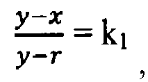
wobei k1 0,3 bis 0,5, bevorzugter 0,35 bis 0,45 und am bevorzugtesten ungefähr 0,4 beträgt, und/oder
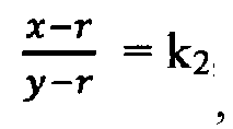
wobei k2 0,5 bis 0,7, bevorzugter 0,55 bis 0,65 und am bevorzugtesten ungefähr 0,6 beträgt, erfüllen.
wobei k1 0,3 bis 0,5, bevorzugter 0,35 bis 0,45 und am bevorzugtesten ungefähr 0,4 beträgt, und/oder
wobei k2 0,5 bis 0,7, bevorzugter 0,55 bis 0,65 und am bevorzugtesten ungefähr 0,6 beträgt, erfüllen.
11. Vorrichtung nach Anspruch 10, dadurch gekennzeichnet, dass
die austauschbaren Bodenplatten (43) unterschiedliche Formen und/oder Oberflächeneigenschaften, insbesondere unterschiedliche Antihafteigenschaften, haben, unterschiedliche Werkstoffe, insbesondere unterschiedliche Weichheits- und/oder Flexibilitätseigenschaften aufweisen, umfassen, und/oder unterschiedliche Öffnungen zum Ablassen von dem Lebensmittelprodukt durch Schleudern entzogenen Flüssigkeiten umfassen.
die austauschbaren Bodenplatten (43) unterschiedliche Formen und/oder Oberflächeneigenschaften, insbesondere unterschiedliche Antihafteigenschaften, haben, unterschiedliche Werkstoffe, insbesondere unterschiedliche Weichheits- und/oder Flexibilitätseigenschaften aufweisen, umfassen, und/oder unterschiedliche Öffnungen zum Ablassen von dem Lebensmittelprodukt durch Schleudern entzogenen Flüssigkeiten umfassen.
12. Vorrichtung nach einem der vorangehenden Ansprüche, dadurch gekennzeichnet, dass das Schleuderelement (9a, 9b) außerdem um eine dritte Drehachse (17a, 17b) gedreht
werden kann, die insbesondere hauptsächlich senkrecht zu der ersten Drehachse (11a,
11b) verläuft, hauptsächlich parallel zu der zweiten Drehachse (13) verläuft, zumindest
teilweise durch den Innenraum (15a, 15b) verläuft, sich zwischen der Bodenwand (37)
und/oder der Bodenplatte (43) und der Öffnung (41) befindet, vorzugsweise ungefähr
13 mm, insbesondere wenn der Innendurchmesser (D) des Innenraums (15a, 15b) ungefähr
1200 mm beträgt, 2% bis 3%, bevorzugter 2,5% bis 3,5%, am bevorzugtesten ungefähr
4% der Höhe (y) des Schleuderelements (9a, 9b) und/oder 5% bis 50%, bevorzugter 7,5%
bis 30%, am bevorzugtesten ungefähr 10% des Radius (r) der Ecke (35), und/oder oberhalb
der Bodenwand (37) und/oder der Bodenplatte (43), zwischen den Seitenwänden (37) verläuft
und/oder die erste Drehachse (11a, 11b) schneidet, insbesondere um das Schleuderelement
(9a, 9b) aus der Füllstellung und/oder der Schleuderstellung in die Entladestellung
oder umgekehrt zu bewegen,
und/oder dass sich im Bereich der Bodenwand (37), der Bodenplatte (43), der Seitenwand (37) und/oder der Ecke (35) zumindest teilweise eine Schicht eines Werkstoffs, der weicher als der Werkstoff der Bodenwand (37), der Bodenplatte (43) und/oder der Seitenwand (37) ist, befindet, die insbesondere als Abdeckung für die Bodenwand (37), die Bodenplatte (43), die Seitenwand (37) und/oder die Ecke (35) vorgesehen ist.
und/oder dass sich im Bereich der Bodenwand (37), der Bodenplatte (43), der Seitenwand (37) und/oder der Ecke (35) zumindest teilweise eine Schicht eines Werkstoffs, der weicher als der Werkstoff der Bodenwand (37), der Bodenplatte (43) und/oder der Seitenwand (37) ist, befindet, die insbesondere als Abdeckung für die Bodenwand (37), die Bodenplatte (43), die Seitenwand (37) und/oder die Ecke (35) vorgesehen ist.
13. Vorrichtung nach einem der vorangehenden Ansprüche, gekennzeichnet durch
mindestens ein Entlademittel (19a, 19b, 21, 27), wobei das Lebensmittelprodukt, insbesondere in der Entladestellung des Schleuderelements (9a, 9b), aus dem Innenraum (15a, 15b) zu dem Entlademittel (19a, 19b, 21, 27) bewegbar ist, vorzugsweise durch Drehen des Schleuderelements (15a, 15b) um die dritte Drehachse (17a, 17b), und/oder das Lebensmittelprodukt durch das Entlademittel (19a, 19b, 21, 27) zu einer Lebensmittelproduktausgabestelle (31) der Vorrichtung (1, 1') beförderbar ist, wobei insbesondere durch das Entlademittel (19a, 19b, 21, 27) das von unterschiedlichen Schleuderelementen (9a, 9b) aus weitergeleitete Lebensmittelprodukt zu einer Ausgabestelle (33) der Vorrichtung (1) beförderbar ist, wobei vorzugsweise das Entlademittel mindestens zwei, vorzugsweise eine Mehrzahl von Sammelmitteln (19a, 19b) umfasst, mittels derer das Lebensmittelprodukt zu der Ausgabestelle (31) befördert wird und/oder zu einem Zwischenelement (21) befördert wird, das das Lebensmittelprodukt zu der Ausgabestelle (31) befördert.
mindestens ein Entlademittel (19a, 19b, 21, 27), wobei das Lebensmittelprodukt, insbesondere in der Entladestellung des Schleuderelements (9a, 9b), aus dem Innenraum (15a, 15b) zu dem Entlademittel (19a, 19b, 21, 27) bewegbar ist, vorzugsweise durch Drehen des Schleuderelements (15a, 15b) um die dritte Drehachse (17a, 17b), und/oder das Lebensmittelprodukt durch das Entlademittel (19a, 19b, 21, 27) zu einer Lebensmittelproduktausgabestelle (31) der Vorrichtung (1, 1') beförderbar ist, wobei insbesondere durch das Entlademittel (19a, 19b, 21, 27) das von unterschiedlichen Schleuderelementen (9a, 9b) aus weitergeleitete Lebensmittelprodukt zu einer Ausgabestelle (33) der Vorrichtung (1) beförderbar ist, wobei vorzugsweise das Entlademittel mindestens zwei, vorzugsweise eine Mehrzahl von Sammelmitteln (19a, 19b) umfasst, mittels derer das Lebensmittelprodukt zu der Ausgabestelle (31) befördert wird und/oder zu einem Zwischenelement (21) befördert wird, das das Lebensmittelprodukt zu der Ausgabestelle (31) befördert.
14. Vorrichtung nach einem der vorangehenden Ansprüche, gekennzeichnet durch
mindestens eine Luftschleusenvorrichtung (23) und/oder mindestens ein zweites Ventilmittel, das insbesondere mindestens ein Drehventil (24') und/oder eine Drehluftschleuse umfasst, durch die das Lebensmittelprodukt zu der Ausgabestelle (33) befördert wird, wobei insbesondere das Lebensmittelprodukt durch das Sammelmittel (19a, 19b) und/oder das Zwischenelement (21) zu dem zweiten Ventilmittel und/oder in die Luftschleusenvorrichtung (23, 23') beförderbar ist und/oder das Lebensmittelprodukt durch mindestens ein Luftschleusenförderelement (27) und/oder das zweite Ventilmittel zu einem Luftschleusenausgang, der insbesondere die Ausgabestelle (31) der Vorrichtung (1, 1') darstellt, und/oder auf eine Produktausgabevorrichtung (33) beförderbar ist.
mindestens eine Luftschleusenvorrichtung (23) und/oder mindestens ein zweites Ventilmittel, das insbesondere mindestens ein Drehventil (24') und/oder eine Drehluftschleuse umfasst, durch die das Lebensmittelprodukt zu der Ausgabestelle (33) befördert wird, wobei insbesondere das Lebensmittelprodukt durch das Sammelmittel (19a, 19b) und/oder das Zwischenelement (21) zu dem zweiten Ventilmittel und/oder in die Luftschleusenvorrichtung (23, 23') beförderbar ist und/oder das Lebensmittelprodukt durch mindestens ein Luftschleusenförderelement (27) und/oder das zweite Ventilmittel zu einem Luftschleusenausgang, der insbesondere die Ausgabestelle (31) der Vorrichtung (1, 1') darstellt, und/oder auf eine Produktausgabevorrichtung (33) beförderbar ist.
15. Vorrichtung nach einem der vorangehenden Ansprüche, dadurch gekennzeichnet, dass das Fördermittel (7), insbesondere das Zuführungsmittel (7b) und/oder das Teilungselement
(7a), die Bratgefäßfördervorrichtung (5), das Produktzuführungsmittel, das Entlademittel
(19a, 19b), das Sammelmittel (19a, 19b), das Zwischenelement (21), das Luftschleusenförderelement
(27) und/oder die Produktausgabevorrichtung mindestens ein Förderband, mindestens
ein Kanal, mindestens eine Schurre, mindestens eine Rutsche, mindestens einen Drahtgurt
und/oder mindestens eine Rampe umfassen/umfasst.
16. Vorrichtung nach einem der vorangehenden Ansprüche, dadurch gekennzeichnet, dass die Vorrichtung (1, 1') zumindest teilweise in einem Gehäuse, insbesondere einem
Druckbehälter (3), untergebracht ist, in dem Vakuumbedingungen vorgesehen sein können.
17. Verfahren zum Schleudern mindestens eines Lebensmittelprodukts, wobei das über ein
Speisemittel (5) und ein Teilungselement (7a) zugeführte Lebensmittelprodukt durch
mindestens ein Fördermittel (7, 7a, 7b) zu mindestens einem Schleuderelement (9a,
9b), das einen Innenraum (15a, 15b) zur Aufnahme des Lebensmittelprodukts aufweist
und so angepasst ist, dass es um eine erste Drehachse (11a, 11b) gedreht wird, befördert
wird und wobei vor und/oder während der Beförderung des Lebensmittelprodukts zu dem
Schleuderelement (9a, 9b) das Fördermittel (7b) zumindest teilweise so in den Innenraum
(15a, 15b) eingeführt wird, dass mindestens ein Zuführungsmittel (7b) des Fördermittels
(7) zumindest teilweise in den Innenraum (15a, 15b) hinein- oder aus diesem herausbewegt
wird, dadurch gekennzeichnet, dass
das Zuführungsmittel (7b) so relativ zu dem Teilungselement (7a) um eine horizontale zweite Drehachse (13) geschwenkt wird, dass das Zuführungsmittel (7b) in den Innenraum (15a, 15b) abgesenkt und aus diesem herausgehoben werden kann.
das Zuführungsmittel (7b) so relativ zu dem Teilungselement (7a) um eine horizontale zweite Drehachse (13) geschwenkt wird, dass das Zuführungsmittel (7b) in den Innenraum (15a, 15b) abgesenkt und aus diesem herausgehoben werden kann.
18. Verfahren nach Anspruch 17, dadurch gekennzeichnet, dass
während oder nach der Beförderung des Lebensmittelprodukts zu dem Schleuderelement (9a, 9b) das Fördermittel zumindest teilweise aus dem Innenraum (15a, 15b) herausgezogen wird und/oder das Lebensmittelprodukt auf einer bereits vorhandenen Lebensmittelproduktschicht innerhalb des Schleuderelements (9a, 9b) platziert wird.
während oder nach der Beförderung des Lebensmittelprodukts zu dem Schleuderelement (9a, 9b) das Fördermittel zumindest teilweise aus dem Innenraum (15a, 15b) herausgezogen wird und/oder das Lebensmittelprodukt auf einer bereits vorhandenen Lebensmittelproduktschicht innerhalb des Schleuderelements (9a, 9b) platziert wird.
19. Verfahren nach Anspruch 17 oder 18, dadurch gekennzeichnet, dass
das Lebensmittelprodukt so zu dem Schleuderelement (9a, 9b) befördert und/oder von diesem wegbefördert wird, dass es zu dem Fördermittel (7, 7a, 7b) weitergeleitet wird, von einem Element des Fördermittels zu einem anderen Element des Fördermittels, von dem Fördermittel zu dem Schleuderelement und/oder von dem Schleuderelement (9a, 9b) zu einer Ausgabestelle (31) der Vorrichtung (1, 1') weitergeleitet wird durch eine Gleitbewegung und/oder mit einer minimierten Gleithöhe und/oder mit einer Geschwindigkeit im Moment des Aufpralls am Ende der Weiterleitung, die unterhalb einer vordefinierten Maximalgeschwindigkeit liegt.
das Lebensmittelprodukt so zu dem Schleuderelement (9a, 9b) befördert und/oder von diesem wegbefördert wird, dass es zu dem Fördermittel (7, 7a, 7b) weitergeleitet wird, von einem Element des Fördermittels zu einem anderen Element des Fördermittels, von dem Fördermittel zu dem Schleuderelement und/oder von dem Schleuderelement (9a, 9b) zu einer Ausgabestelle (31) der Vorrichtung (1, 1') weitergeleitet wird durch eine Gleitbewegung und/oder mit einer minimierten Gleithöhe und/oder mit einer Geschwindigkeit im Moment des Aufpralls am Ende der Weiterleitung, die unterhalb einer vordefinierten Maximalgeschwindigkeit liegt.
20. Verfahren nach einem der Ansprüche 17 bis 19, dadurch gekennzeichnet, dass
das Lebensmittelprodukt durch das Fördermittel in der Nähe einer Seitenwand (39) des Schleuderelements (9a, 9b) und/oder einer Ecke zwischen der Seitenwand (39) und einer Bodenwand (37) und/oder einer Bodenplatte (43) platziert wird.
das Lebensmittelprodukt durch das Fördermittel in der Nähe einer Seitenwand (39) des Schleuderelements (9a, 9b) und/oder einer Ecke zwischen der Seitenwand (39) und einer Bodenwand (37) und/oder einer Bodenplatte (43) platziert wird.
21. Verfahren nach einem der Ansprüche 17 bis 20, dadurch gekennzeichnet, dass
eine Länge des Zuführungsmittels (7b), insbesondere teleskopisch, verändert wird und/oder dass das Lebensmittelprodukt durch Fördermittel (7), insbesondere das Zuführungsmittel (7b), zu mindestens zwei, vorzugsweise einer Mehrzahl von Schleuderelementen (9a, 9b) befördert wird, wobei das Lebensmittelprodukt alternativ zu einem der Schleuderelemente (9a) befördert wird, insbesondere das Zuführungsmittel (7b) alternativ zumindest teilweise in einem der Schleuderelemente (9b) positioniert wird und/oder in umgekehrten Richtungen betätigt wird und/oder das Lebensmittelprodukt durch mindestens ein Teilungselement (7a) des Fördermittels (7), insbesondere durch Betätigung des Teilungselements (7a) in umgekehrter Richtung, zu mindestens zwei, insbesondere einer Mehrzahl von Zuführungsmitteln (7b) befördert wird, wobei das Lebensmittelprodukt über jedes der Zuführungsmittel (7b) zu einem jeweiligen Schleuderelement (9a, 9b), dem das Zuführungsmittel (7b) zugeordnet ist, befördert wird.
eine Länge des Zuführungsmittels (7b), insbesondere teleskopisch, verändert wird und/oder dass das Lebensmittelprodukt durch Fördermittel (7), insbesondere das Zuführungsmittel (7b), zu mindestens zwei, vorzugsweise einer Mehrzahl von Schleuderelementen (9a, 9b) befördert wird, wobei das Lebensmittelprodukt alternativ zu einem der Schleuderelemente (9a) befördert wird, insbesondere das Zuführungsmittel (7b) alternativ zumindest teilweise in einem der Schleuderelemente (9b) positioniert wird und/oder in umgekehrten Richtungen betätigt wird und/oder das Lebensmittelprodukt durch mindestens ein Teilungselement (7a) des Fördermittels (7), insbesondere durch Betätigung des Teilungselements (7a) in umgekehrter Richtung, zu mindestens zwei, insbesondere einer Mehrzahl von Zuführungsmitteln (7b) befördert wird, wobei das Lebensmittelprodukt über jedes der Zuführungsmittel (7b) zu einem jeweiligen Schleuderelement (9a, 9b), dem das Zuführungsmittel (7b) zugeordnet ist, befördert wird.
22. Verfahren nach einem der Ansprüche 17 bis 21, dadurch gekennzeichnet, dass
das Schleuderelement (9a, 9b) mit einer ersten Geschwindigkeit um die erste Drehachse (11a, 11b) gedreht wird, um dem Lebensmittelprodukt Flüssigkeit zu entziehen, wobei insbesondere während der Beförderung des Lebensmittelprodukts zu einem ersten Schleuderelement (9a), insbesondere wenn sich das Zuführungsmittel (7b) zumindest teilweise innerhalb des Innenraums (15a) des ersten Schleuderelements (9a) befindet, mindestens ein zweites Schleuderelement (9b) mit der ersten Geschwindigkeit um seine erste Drehachse (11b) gedreht wird, wobei sich das Zuführungsmittel (7b) vorzugsweise außerhalb des Innenraums (15b) des zweiten Schleuderelements (9b) befindet, und/oder das zweite Schleuderelement (9b) sich in einer Entladestellung befindet oder in diese gebracht wird, wobei insbesondere die Beschleunigung auf die erste Geschwindigkeit und/oder die Verzögerung von der ersten Geschwindigkeit gesteuert wird, um eine Relativbewegung zwischen dem Lebensmittelprodukt und dem Schleuderelement (9a, 9b) zu reduzieren und/oder eine Relativbewegung einzelner Stücke des Lebensmittelprodukts relativ zueinander zu reduzieren.
das Schleuderelement (9a, 9b) mit einer ersten Geschwindigkeit um die erste Drehachse (11a, 11b) gedreht wird, um dem Lebensmittelprodukt Flüssigkeit zu entziehen, wobei insbesondere während der Beförderung des Lebensmittelprodukts zu einem ersten Schleuderelement (9a), insbesondere wenn sich das Zuführungsmittel (7b) zumindest teilweise innerhalb des Innenraums (15a) des ersten Schleuderelements (9a) befindet, mindestens ein zweites Schleuderelement (9b) mit der ersten Geschwindigkeit um seine erste Drehachse (11b) gedreht wird, wobei sich das Zuführungsmittel (7b) vorzugsweise außerhalb des Innenraums (15b) des zweiten Schleuderelements (9b) befindet, und/oder das zweite Schleuderelement (9b) sich in einer Entladestellung befindet oder in diese gebracht wird, wobei insbesondere die Beschleunigung auf die erste Geschwindigkeit und/oder die Verzögerung von der ersten Geschwindigkeit gesteuert wird, um eine Relativbewegung zwischen dem Lebensmittelprodukt und dem Schleuderelement (9a, 9b) zu reduzieren und/oder eine Relativbewegung einzelner Stücke des Lebensmittelprodukts relativ zueinander zu reduzieren.
23. Verfahren nach einem der Ansprüche 17 bis 22, dadurch gekennzeichnet, dass
das Fördermittel (7, 7b) zumindest vorübergehend so innerhalb des Innenraums (15a, 15b) positioniert wird, dass das Lebensmittelprodukt durch eine Gleitbewegung in die Ecke (35) des Schleuderelements (9a, 9b), die zwischen einer Bodenwand (37) und/oder einer Bodenplatte (43) einerseits und einer Seitenwand (39) des Schleuderelements (9a, 9b) andererseits ausgebildet ist, befördert wird und/oder dass die Gleithöhe (hd,db), um die das Lebensmittelprodukt von dem Fördermittel (7), insbesondere dem Zuführungsmittel (7b), herabgleitet, minimiert wird.
das Fördermittel (7, 7b) zumindest vorübergehend so innerhalb des Innenraums (15a, 15b) positioniert wird, dass das Lebensmittelprodukt durch eine Gleitbewegung in die Ecke (35) des Schleuderelements (9a, 9b), die zwischen einer Bodenwand (37) und/oder einer Bodenplatte (43) einerseits und einer Seitenwand (39) des Schleuderelements (9a, 9b) andererseits ausgebildet ist, befördert wird und/oder dass die Gleithöhe (hd,db), um die das Lebensmittelprodukt von dem Fördermittel (7), insbesondere dem Zuführungsmittel (7b), herabgleitet, minimiert wird.
24. Verfahren nach einem der Ansprüche 17 bis 23, dadurch gekennzeichnet, dass
das Schleuderelement (9a, 9b) zumindest vorübergehend mit einer zweiten Geschwindigkeit, die geringer als die erste Geschwindigkeit ist, um die erste Drehachse (11a, 11b) gedreht wird, dass insbesondere während des Befüllens des Schleuderelements (9a, 9b) mit dem Lebensmittelprodukt das Schleuderelement (9a, 9b) um 360° um die erste Drehachse (11a, 11b) und/oder um mehr als 360° um die erste Drehachse (11a, 11b) gedreht wird, vorzugsweise derart, dass das Lebensmittelprodukt auf der bereits vorhandenen Lebensmittelproduktschicht innerhalb des Schleuderelements (9a, 9b) platziert wird.
das Schleuderelement (9a, 9b) zumindest vorübergehend mit einer zweiten Geschwindigkeit, die geringer als die erste Geschwindigkeit ist, um die erste Drehachse (11a, 11b) gedreht wird, dass insbesondere während des Befüllens des Schleuderelements (9a, 9b) mit dem Lebensmittelprodukt das Schleuderelement (9a, 9b) um 360° um die erste Drehachse (11a, 11b) und/oder um mehr als 360° um die erste Drehachse (11a, 11b) gedreht wird, vorzugsweise derart, dass das Lebensmittelprodukt auf der bereits vorhandenen Lebensmittelproduktschicht innerhalb des Schleuderelements (9a, 9b) platziert wird.
25. Verfahren nach einem der Ansprüche 17 bis 24, dadurch gekennzeichnet, dass
das Schleuderelement (9a, 9b) vor und/oder bei der Beförderung des Lebensmittelprodukts zu dem Schleuderelement (9a, 9b) in einer Füllstellung gehalten oder in diese gebracht wird, bei und/oder vor der Drehung des Schleuderelements (9a, 9b) mit der ersten Geschwindigkeit in einer Schleuderstellung gehalten oder in diese gebracht wird und in einer Entladestellung gehalten oder in diese gebracht wird, um das Lebensmittelprodukt aus dem Schleuderelement (9a, 9b) zu entladen, wobei in der Füllstellung und in der Schleuderstellung eine Öffnung (41) des Schleuderelements (9a, 9b) nach oben gerichtet ist, und dass das Schleuderelement (9a, 9b) um eine dritte Drehachse (17a, 17b) gedreht wird, um das Schleuderelement (9a, 9b) aus der Füllstellung oder Schleuderstellung in die Entladestellung oder aus der Entladestellung in die Füllstellung oder Schleuderstellung zu bewegen, wobei die zweite Geschwindigkeit, eine dritte Geschwindigkeit um die dritte Achse (17a, 17b), eine Beschleunigung auf die zweite Geschwindigkeit und/oder auf die dritte Geschwindigkeit und/oder eine Verzögerung von der zweiten Geschwindigkeit und/oder von der dritten Geschwindigkeit, eine Geschwindigkeit mindestens eines Entlademittels und/oder eine Geschwindigkeit des Fördermittels so gesteuert wird/werden, dass innere Kräfte innerhalb einer Lebensmittelproduktschicht minimiert werden und/oder dass eine Gleithöhe des Lebensmittelprodukts minimiert wird, wobei vorzugsweise das Lebensmittelprodukt insbesondere über die Öffnung (41) des Schleuderelements (9a, 9b) auf das Entlademittel (19a, 19b, 21, 27) entladen wird und/oder das Lebensmittelprodukt mittels des Entlademittels (19a, 19b, 21, 27) zu der Ausgabestelle (31) der Vorrichtung (1) befördert wird, wobei insbesondere das Lebensmittelprodukt von dem Schleuderelement (9a, 9b) zu dem Entlademittel (19a, 19b, 21, 27), von einem Element des Entlademittels (19a, 19b) zu einem anderen Element (21) des Entlademittels und/oder von dem Entlademittel (21) zu der Ausgabestelle (31) befördert wird durch eine Gleitbewegung und/oder mit einer minimierten Fallhöhe, insbesondere einer Fallhöhe von weniger als 150 mm, bevorzugter einer Fallhöhe von weniger als 100 mm.
das Schleuderelement (9a, 9b) vor und/oder bei der Beförderung des Lebensmittelprodukts zu dem Schleuderelement (9a, 9b) in einer Füllstellung gehalten oder in diese gebracht wird, bei und/oder vor der Drehung des Schleuderelements (9a, 9b) mit der ersten Geschwindigkeit in einer Schleuderstellung gehalten oder in diese gebracht wird und in einer Entladestellung gehalten oder in diese gebracht wird, um das Lebensmittelprodukt aus dem Schleuderelement (9a, 9b) zu entladen, wobei in der Füllstellung und in der Schleuderstellung eine Öffnung (41) des Schleuderelements (9a, 9b) nach oben gerichtet ist, und dass das Schleuderelement (9a, 9b) um eine dritte Drehachse (17a, 17b) gedreht wird, um das Schleuderelement (9a, 9b) aus der Füllstellung oder Schleuderstellung in die Entladestellung oder aus der Entladestellung in die Füllstellung oder Schleuderstellung zu bewegen, wobei die zweite Geschwindigkeit, eine dritte Geschwindigkeit um die dritte Achse (17a, 17b), eine Beschleunigung auf die zweite Geschwindigkeit und/oder auf die dritte Geschwindigkeit und/oder eine Verzögerung von der zweiten Geschwindigkeit und/oder von der dritten Geschwindigkeit, eine Geschwindigkeit mindestens eines Entlademittels und/oder eine Geschwindigkeit des Fördermittels so gesteuert wird/werden, dass innere Kräfte innerhalb einer Lebensmittelproduktschicht minimiert werden und/oder dass eine Gleithöhe des Lebensmittelprodukts minimiert wird, wobei vorzugsweise das Lebensmittelprodukt insbesondere über die Öffnung (41) des Schleuderelements (9a, 9b) auf das Entlademittel (19a, 19b, 21, 27) entladen wird und/oder das Lebensmittelprodukt mittels des Entlademittels (19a, 19b, 21, 27) zu der Ausgabestelle (31) der Vorrichtung (1) befördert wird, wobei insbesondere das Lebensmittelprodukt von dem Schleuderelement (9a, 9b) zu dem Entlademittel (19a, 19b, 21, 27), von einem Element des Entlademittels (19a, 19b) zu einem anderen Element (21) des Entlademittels und/oder von dem Entlademittel (21) zu der Ausgabestelle (31) befördert wird durch eine Gleitbewegung und/oder mit einer minimierten Fallhöhe, insbesondere einer Fallhöhe von weniger als 150 mm, bevorzugter einer Fallhöhe von weniger als 100 mm.
26. Verfahren nach einem der Ansprüche 17 bis 25, dadurch gekennzeichnet, dass
das Lebensmittelprodukt von unterschiedlichen Schleuderelementen (9a, 9b), insbesondere dem ersten Schleuderelement (9a) und dem zweiten Schleuderelement (9b), vorzugsweise mittels des Entlademittels (19a, 19b, 21, 27), zu der Ausgabestelle (31) der Vorrichtung (1) wegbefördert wird, wobei insbesondere das Entlademittel mindestens zwei, vorzugsweise eine Mehrzahl von Sammelmitteln (19a, 19b) umfasst, mittels derer das Lebensmittelprodukt zu der Ausgabestelle befördert wird oder zu mindestens einem Zwischenelement (21), das das Lebensmittelprodukt zu der Ausgabestelle (31) befördert, befördert wird.
das Lebensmittelprodukt von unterschiedlichen Schleuderelementen (9a, 9b), insbesondere dem ersten Schleuderelement (9a) und dem zweiten Schleuderelement (9b), vorzugsweise mittels des Entlademittels (19a, 19b, 21, 27), zu der Ausgabestelle (31) der Vorrichtung (1) wegbefördert wird, wobei insbesondere das Entlademittel mindestens zwei, vorzugsweise eine Mehrzahl von Sammelmitteln (19a, 19b) umfasst, mittels derer das Lebensmittelprodukt zu der Ausgabestelle befördert wird oder zu mindestens einem Zwischenelement (21), das das Lebensmittelprodukt zu der Ausgabestelle (31) befördert, befördert wird.
27. Verfahren nach einem der Ansprüche 17 bis 26, dadurch gekennzeichnet, dass
das Lebensmittelprodukt als gebratenes Produkt dem Fördermittel über mindestens eine Bratgefäßfördervorrichtung zugeführt wird und/oder als rohes Material und/oder ungebratenes Material dem Fördermittel über mindestens ein Produktzuführungsmittel zugeführt wird.
das Lebensmittelprodukt als gebratenes Produkt dem Fördermittel über mindestens eine Bratgefäßfördervorrichtung zugeführt wird und/oder als rohes Material und/oder ungebratenes Material dem Fördermittel über mindestens ein Produktzuführungsmittel zugeführt wird.
1. Dispositif (1, 1') pour la centrifugation d'au moins un produit alimentaire agencé
sur le dispositif (1, 1') via un moyen d'alimentation (5), le dispositif (1, 1') comprenant
au moins un moyen de transport (7, 7a, 7b) et au moins un élément de centrifugation
(9a, 9b) ayant un espace intérieur (15a, 15b) destiné à recevoir le produit alimentaire,
et étant conçu pour être amené à tourner autour d'un premier axe de rotation (11a,
11b), dans lequel le produit alimentaire pouvant être transporté jusque dans l'espace
intérieur (15a, 15b) via le moyen de transport (3, 5, 6', 7, 7a, 7b), le moyen de
transport comprenant un élément de division (7a) et au moins un moyen d'acheminement
(7b), dans lequel le produit alimentaire étant transporté vers le moyen d'acheminement
(7b) via l'élément de division (7a), et via le moyen d'acheminement (7b) vers l'élément
de centrifugation (9a, 9b), et dans lequel de plus le moyen de transport (7, 7b) peut
être inséré au moins partiellement dans l'espace intérieur (15a, 15b), et peut en
être extrait, de telle sorte que le moyen d'acheminement (7b) peut être positionné
au moins partiellement dans l'espace intérieur (15a, 15b) en déplaçant au moins partiellement
le moyen d'acheminement (7b), caractérisé en ce que
le moyen d'acheminement (7b) peut être tourné par rapport à l'élément de division (7a) autour d'un second axe de rotation horizontal (13), de telle sorte que le moyen d'acheminement (7b) peut être abaissé dans l'espace intérieur (15a, 15b), et être levé à l'extérieur de celui-ci.
le moyen d'acheminement (7b) peut être tourné par rapport à l'élément de division (7a) autour d'un second axe de rotation horizontal (13), de telle sorte que le moyen d'acheminement (7b) peut être abaissé dans l'espace intérieur (15a, 15b), et être levé à l'extérieur de celui-ci.
2. Dispositif selon la revendication 1, caractérisé en ce qu'une longueur du moyen d'acheminement (7b) peut être modifiée, en particulier de manière
télescopique.
3. Dispositif selon la revendication 1 ou 2, caractérisé par au moins deux éléments de centrifugation (9a, 9b), et de préférence plus, dans lequel
le produit alimentaire peut être transporté de manière alternée vers l'un des les
éléments de centrifugation (9a), et en particulier le moyen d'acheminement (7, 7a,
7b) peut-être positionné de manière alternée au moins partiellement dans l'un des
éléments de centrifugation, et/ou peut-être actionné dans des directions inverses.
4. Dispositif selon l'une quelconque des revendications précédentes, caractérisé en ce que le moyen de transport (7) comprend au moins un élément de division (7a) pour transporter
de manière alternée le produit alimentaire, en particulier par un actionnement dans
une direction inverse, vers au moins deux moyens d'acheminement (7b), et de préférence
plus, dans lequel, via chacun des moyens d'acheminement (7b), le produit alimentaire
peut être transporté vers un élément de centrifugation (9a, 9b) respectif auquel le
moyen d'acheminement (7b) est attribuée.
5. Dispositif selon la revendication 4, caractérisé en ce que le moyen d'acheminement (7b) et l'élément de division (7a) sont au moins partiellement
d'un seul tenant.
6. Dispositif selon l'une quelconque des revendications précédentes, caractérisé en ce que le second axe de rotation (13) est perpendiculaire au premier axe de rotation (11a,
11b), et/ou le moyen d'acheminement (7b) peut-être tourné via une connexion articulée,
en particulier entre le moyen d'acheminement (7b) et l'élément de division (7a).
7. Dispositif selon l'une quelconque des revendications précédentes, caractérisé en ce que le moyen d'alimentation comprend au moins un dispositif de transport de friture (5),
au moins un moyen de fourniture de produit, et/ou un premier moyen formant vanne,
comprenant en particulier au moins une vanne rotative (4') et/ou un sas à air rotatif
pour fournir le produit alimentaire au moyen de transport (7, 7a, 7b), et/ou le produit
alimentaire est fourni au moyen de transport (7, 7a, 7b).
8. Dispositif selon l'une quelconque des revendications précédentes, caractérisé en ce que l'élément de centrifugation (9a, 9b) comprend au moins une ouverture (41), de préférence
seulement une ouverture unique (41), à travers laquelle le produit alimentaire et
transporté dans et/ou à l'extérieur de l'élément de centrifugation (9a, 9b), dans
lequel de préférence dans une position de remplissage et/ou une position de centrifugation
de l'élément de centrifugation (9a, 9b), l'ouverture est orientée principalement vers
le haut et/ou est orientée principalement vers le bas dans une position d'évacuation
de l'élément de centrifugation (9a, 9b).
9. Dispositif selon la revendication 8, caractérisé en ce que l'ouverture (41) a un diamètre intérieur (d), en particulaire étant plus petit que
le diamètre intérieur maximum de l'espace intérieur (15a, 15b), et/ou a au moins partiellement
une forme de section transversale conique, le diamètre intérieur de l'ouverture étant
en particulier d'environ 70 % à 90 %, de manière plus préférée d'environ 75 % à 85
%, et de la manière la plus préférée d'environ 80 % du diamètre intérieur (D) de l'espace
intérieur (15a, 15b), l'ouverture a un angle de cône (ϕ) de 20° à 40°, de manière
préférée de 25° à 35°, de la manière la plus préférée d'environ 33,5° par rapport
au premier axe de rotation (11a, 11b), l'ouverture a une longueur de cône (y-x) de
10 % à 50 %, de préférence de 20 % à 40 %, de la manière la plus préférée d'environ
30 % de la hauteur (y) de l'élément de centrifugation (9a, 9b), en particulier une
longueur de cône d'environ 120 à environ 200 mm, de manière plus préférée d'environ
140 à environ 180 mm, et de la manière la plus préférée d'environ 160 mm, en particulier
lorsque le diamètre intérieur (D) de l'espace intérieur (15a, 15b) est environ 1200
mm, et/ou le moyen d'acheminement (7b) est incliné d'un angle (α) par rapport à un
axe horizontal et/ou un plan de l'ouverture (41), dans lequel l'angle (α) satisfait
complètement la relation
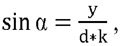
y étant la hauteur de l'élément de centrifugation, d étant le diamètre intérieur de l'ouverture (41), et k étant une constante dans une plage de 0,83 à 0,91, de manière plus préférée de 0,85 à 0,89, et de la manière la plus préférée d'environ 0,87.
y étant la hauteur de l'élément de centrifugation, d étant le diamètre intérieur de l'ouverture (41), et k étant une constante dans une plage de 0,83 à 0,91, de manière plus préférée de 0,85 à 0,89, et de la manière la plus préférée d'environ 0,87.
10. Dispositif selon l'une quelconque des revendications précédentes, caractérisé en ce que l'élément de centrifugation (9a, 9b) comprend au moins une paroi de fond (37), disposée
en particulier opposée à l'ouverture (41), et au moins une paroi latérale (39), en
particulier cylindrique, elliptique et/ou circulaire, dans lequel de préférence au
moins une plaque de fond (43), en particulaire au moins partiellement interchangeable,
peut-être positionnée au-dessus de la paroi de fond (37), et dans lequel de préférence
le coin (35) situé entre la paroi de fond (37) et/ou la plaque de fond (43) sur le
premier côté, et la paroi latérale (39) sur l'autre côté, est au moins partiellement
arrondi, en particulier avec un rayon (r), de préférence un rayon (r) d'environ 100
à 150 mm, de la manière la plus préférée d'environ 120 mm, et/ou la longueur de cône
(y-x), la hauteur (y) de l'élément de centrifugation et le rayon (r) satisfont la
relation
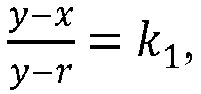
avec k1 étant de 0,3 à 0,5, de manière plus préférée de 0,35 à 0,45, et de la manière la plus préférée d'environ 0,4, et/ou
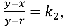
avec k2 étant de 0,5 à 0,7, de manière plus préférée de 0,55 à 0,65, et de la manière la plus préférée d'environ 0,6.
avec k1 étant de 0,3 à 0,5, de manière plus préférée de 0,35 à 0,45, et de la manière la plus préférée d'environ 0,4, et/ou
avec k2 étant de 0,5 à 0,7, de manière plus préférée de 0,55 à 0,65, et de la manière la plus préférée d'environ 0,6.
11. Dispositif selon la revendication 10, caractérisé en ce que les plaques de fonds interchangeable (43) ont des formes différentes, et/ou des propriétés
de surface différentes, en particulier des propriétés de non-adhérence différentes,
comprennent de matériaux différents, ayant en particulier des propriétés de souplesse
et/ou de flexibilité différentes, et/ou comprennent différentes ouvertures pour verser
des fluides extraits du produit alimentaire par centrifugation.
12. Dispositif selon l'une quelconque des revendications précédentes, caractérisé en ce que l'élément de centrifugation (9a, 9b) peut en outre être tourné autour d'un troisième
axe de rotation (17a, 17b), en particulier étant principalement perpendiculaire au
premier axe de rotation (11a, 11b), étant principalement parallèle au deuxième axe
de rotation (13), s'étendant au moins partiellement à travers l'espace intérieur (15a,
15b), étant positionnée entre la paroi de fond (37) et/ou la plaque de fond (43) et
l'ouverture (41), de préférence d'environ 13 mm, en particulier lorsque le diamètre
intérieur (D) de l'espace intérieur (15a, 15b) est environ 1200 mm, de 2 % à 3 %,
de manière plus préférée de 2,5 % à 3,5 %, de la manière la plus préférée d'environ
4 % de la hauteur (y) de l'élément de centrifugation (9a, 9b), et/ou de 5 % à 50 %,
de manière plus préférée de 7,5 % à 30 %, de la manière la plus préférée d'environ
10 % du rayon (r) du coin (35), et/ou au-dessus de la paroi de fond (37) et/ou de
la plaque de fond (43), s'étendant entre les parois latérales (37) et/ou recoupant
le premier axe de rotation (11a, 11b), en particulier pour transférer l'élément de
centrifugation (9a, 9b) depuis la position de remplissage et/ou la position de centrifugation
vers la position d'évacuation, ou vice versa,
et/ou en ce que dans la zone de la paroi de fond (37), de la plaque de fond (43), de la paroi latérale (37) et/ou du coin (35) est positionnée au moins partiellement une couche d'un matériau plus souple que le matériau de la paroi de fond (37), de la plaque de fond (43) et/ou de la paroi latérale (37), en particulier fourni sous la forme d'un recouvrement de la paroi de fond (37), de la plaque de fond (43), de la paroi latérale (37) et/ou du coin (35).
et/ou en ce que dans la zone de la paroi de fond (37), de la plaque de fond (43), de la paroi latérale (37) et/ou du coin (35) est positionnée au moins partiellement une couche d'un matériau plus souple que le matériau de la paroi de fond (37), de la plaque de fond (43) et/ou de la paroi latérale (37), en particulier fourni sous la forme d'un recouvrement de la paroi de fond (37), de la plaque de fond (43), de la paroi latérale (37) et/ou du coin (35).
13. Dispositif selon l'une quelconque des revendications précédentes, caractérisé par au moins un moyen d'évacuation (19a, 19b, 21, 27), dans lequel le produit alimentaire
peut être transféré, en particulier dans la position d'évacuation de l'élément de
centrifugation (9a, 9b), depuis l'espace intérieur (15a, 15b) vers le moyen d'évacuation
(19a, 19b, 21, 27), de préférence en faisant tourner l'élément de centrifugation (15a,
15b) autour du troisième axe de rotation (17a, 17b), et/ou le produit alimentaire
peut être transporté par l'intermédiaire des moyens d'évacuation (19a, 19b, 21, 27)
vers une sortie de produit alimentaire (31) du dispositif (1, 1'), dans lequel en
particulier par l'intermédiaire des moyens d'évacuation (19a, 19b, 21, 27), le produit
alimentaire transféré depuis différents éléments de centrifugation (9a, 9b) peut être
transféré vers une sortie (33) du dispositif (1), dans lequel de préférence le moyen
d'évacuation comprend au moins deux moyens de recueil (19a, 19b), et de préférence
plus, par l'intermédiaire desquels le produit alimentaire est transporté vers la sortie
(31), et/ou est transporté vers un élément intermédiaire (21) transportant le produit
alimentaire vers la sortie (31).
14. Dispositif selon l'une quelconque des revendications précédentes, caractérisé par au moins un dispositif formant sas à air (23) et/ou au moins un second moyen formant
vanne, comprenant en particulier au moins une vanne rotative (24') et/ou un sas à
air rotatif, à travers lequel le produit alimentaire est transporté vers la sortie
(33), dans lequel en particulier le produit alimentaire peut être transporté via le
moyen de recueil (19a, 19b) et/ou l'élément intermédiaire (21) vers le second moyen
formant vanne et/ou jusque dans le dispositif formant sas à air (23, 23'), et/ou le
produit alimentaire peut être transporté par au moins un élément de transport de sas
à air (27) et/ou le deuxième moyen formant vanne vers une sortie de sas à air, représentant
en particulier la sortie (31) du dispositif (1, 1') et/ou jusque sur un dispositif
de sortie de produit (33).
15. Dispositif selon l'une quelconque des revendications précédentes, caractérisé en ce que le moyen de transport (7), en particulier le moyen d'acheminement (7b) et/ou l'élément
de division (7a), le dispositif de transport de friture (5), le moyen de fourniture
de produit, le moyen d'évacuation (19a, 19b), le moyen de recueil (19a, 19b), l'élément
intermédiaire (21), l'élément de transport de sas à air (27) et/ou le dispositif de
sortie de produit comprennent au moins une courroie transporteuse, au moins un conduit,
au moins une goulotte, au moins une coulisse, au moins une bande en treillis de fils
et/ou au moins une rampe.
16. Dispositif selon l'une quelconque des revendications précédentes, caractérisé en ce que le dispositif (1, 1') est reçu au moins partiellement dans un carter, en particulier
un réservoir de pression (3), dans lequel des conditions de vide peuvent être fournies.
17. Procédé pour centrifugé au moins un produit alimentaire, dans lequel le produit alimentaire
fourni via un moyen d'alimentation (5) et un élément de division (7a) est transporté
vers au moins un élément de centrifugation (9a, 9b) ayant un espace intérieur (15a,
15b) destiné à recevoir le produit alimentaire, et étant adapté pour être tourné autour
d'un premier axe de rotation (11a, 11b) par au moins un moyen de transport (7, 7a,
7b), et dans lequel avant et/ou pendant le transport du produit alimentaire vers l'élément
de centrifugation (9a, 9b), le moyen de transport (7b) est inséré au moins partiellement
dans l'espace intérieur (15a, 15b) de telle sorte qu'au moins un moyen d'acheminement
(7b) du moyen de transport (7) est déplacé au moins partiellement dans ou à l'extérieur
de l'espace intérieur (15a, 15b), caractérisé en ce que
le moyen d'acheminement (7b) est articulé autour d'un deuxième axe de rotation horizontale (13) par rapport à l'élément de division (7a), de telle sorte que le moyen d'acheminement (7b) peut être abaisser dans l'espace intérieur (15a, 15b), et levé à l'extérieur de celui-ci.
le moyen d'acheminement (7b) est articulé autour d'un deuxième axe de rotation horizontale (13) par rapport à l'élément de division (7a), de telle sorte que le moyen d'acheminement (7b) peut être abaisser dans l'espace intérieur (15a, 15b), et levé à l'extérieur de celui-ci.
18. Procédé selon la revendication 17, caractérisé en ce que pendant ou après le transport du produit alimentaire vers l'élément de centrifugation
(9a, 9b), le moyen de transport est au moins partiellement extrait de l'espace intérieur
(15a, 15b), et/ou le produit alimentaire est placé sur une couche déjà existante de
produit alimentaire dans l'élément de centrifugation (9a, 9b).
19. Procédé selon la revendication 17 ou 18, caractérisé en ce que le produit alimentaire est transporté vers et/ou depuis l'élément de centrifugation
(9a, 9b) de telle sorte qu'il est transféré vers le moyen de transport (7, 7a, 7b),
transféré depuis un élément du moyen de transport vers un autre élément du moyen de
transport, depuis le moyen de transport vers l'élément de centrifugation et/ou depuis
l'élément de centrifugation (9a, 9b) vers une sortie (31) du dispositif (1, 1') par
un mouvement coulissant et/ou avec une hauteur de coulissement minimiser et/ou avec
une vitesse, au moment de l'impact à la fin du transfert, étant inférieure à une vitesse
maximum prédéfinie.
20. Procédé selon l'une quelconque des revendications 17 à 19, caractérisé en ce que le produit alimentaire est positionné par le moyen de transport prés d'une paroi
latérale (39) d'élément de centrifugation (9a,9b) et/ou un coin d'une paroi latérale
(39) avec une paroi de fond (37) et/ou une plaque de fond (43).
21. Procédé selon l'une quelconque des revendications 17 à 20, caractérisé en ce qu'une longueur du moyen d'acheminement (7b) est modifiée, en particulier de manière
télescopique, et/ou en ce que le produit alimentaire est transporté par le moyen de transport (7), en particulier
le moyen d'acheminement (7b), vers au moins deux éléments de centrifugation (9a, 9b),
et de préférence plus, dans lequel le produit alimentaire est transporté de manière
alternée vers un des éléments de centrifugation (9a), en particulier le moyen d'acheminement
(7b) est positionné de manière alternée au moins partiellement dans l'un des éléments
de centrifugation (9b) et/ou est actionné dans des directions inverses, et/ou le produit
alimentaire est transporté par au moins un élément de division (7a) du moyen de transport
(7), en particulier par un actionnement dans une direction inverse de l'élément de
division (7a) vers au moins deux moyens d'acheminement (7b), en particulier plus de
deux, dans lequel via chacun des moyens d'acheminement (7b), le produit alimentaire
est transporté vers un élément de centrifugation (9a, 9b) respectifs auquel le moyen
d'acheminement (7b) est attribué.
22. Procédé selon l'une quelconque des revendications 17 à 21, caractérisé en ce que l'élément de centrifugation (9a, 9b) est tourné à une première vitesse autour du
premier axe de rotation (11a, 11b) pour extraire du liquide du produit alimentaire,
dans lequel en particulier pendant que le produit alimentaire est transporté vers
un premier élément de centrifugation (9a), en particulier lorsque le moyen d'acheminement
(7b) est situé au moins partiellement dans l'espace intérieur (15a) du premier élément
de centrifugation (9a), au moins un second élément de centrifugation (9b) est tourné
à la première vitesse autour de son premier axe de rotation (11b), de préférence avec
le moyen d'acheminement (7b) étant positionné à l'extérieur de l'espace intérieur
(15b) du second élément de centrifugation (9b), et/ou le second élément de centrifugation
(9b) est dans une position d'évacuation, ou est amené dans celle-ci, dans lequel en
particulier l'accélération jusqu'à la première vitesse et/ou la décélération depuis
la première vitesse est commandé pour réduire un déplacement relatif entre le produit
alimentaire et l'élément de centrifugation (9a, 9b), et/ou pour réduire un déplacement
relatif de pièces uniques du produit alimentaire les unes par rapport aux autres.
23. Procédé selon l'une quelconque des revendications 17 à 22, caractérisé en ce que le moyen de transport (7a, 7b) est positionné dans l'espace intérieur (15a, 15b)
en moins temporairement, de sorte que le produit alimentaire est coulissé dans le
coin (35) de l'élément de centrifugation (9a, 9b) formé entre une paroi de fond (37)
et/ou une plaque de fond (43) d'une part, et une paroi latérale (39) de l'élément
de centrifugation (9a, 9b) d'autre part, et/ou en ce que la hauteur de coulissement (hd,db) du produit alimentaire depuis le moyen de transport (7), en particulier le moyen
d'acheminement (7b), est minimisée.
24. Procédé selon l'une quelconque des revendications 17 à 23, caractérisé en ce que l'élément de centrifugation (9a, 9b) est mis en rotation au moins temporairement
à une seconde vitesse, étant inférieure à la première vitesse, autour du premier axe
de rotation (11a, 11b), en particulier de telle sorte que pendant le remplissage du
produit alimentaire dans l'élément de centrifugation (9a, 9b), l'élément de centrifugation
(9a, 9b) est mis en rotation sur 360° autour du premier axe de rotation (1a, 11b),
et/ou plus de 360° autour du premier axe de rotation (11a, 11b), de préférence de
telle sorte que le produit alimentaire est placé sur la couche déjà existante de produit
alimentaire dans l'élément de centrifugation (9a, 9b).
25. Procédé selon l'une quelconque des revendications 17 à 24, caractérisé en ce que l'élément de centrifugation (9a, 9b) est maintenu ou est amené dans une position
de remplissage avant et/ou lorsque le produit alimentaire est transporté vers l'élément
de centrifugation (9a, 9b), est maintenu ou est amené dans une position de centrifugation
lorsqu'et/ou avant que l'élément de centrifugation (9a, 9b) soit mis en rotation à
la première vitesse, et est maintenu ou amené dans une position d'évacuation pour
évacuer le produit alimentaire à l'extérieur de l'élément de centrifugation (9a, 9b),
dans lequel dans la position de remplissage et dans la position de centrifugation,
une ouverture (41) de l'élément de centrifugation (9a, 9b) est orientée vers le haut,
et en ce que l'élément de centrifugation (9a, 9b) est tourné autour d'un troisième axe de rotation
(17a, 17b) pour transférer l'élément de centrifugation (9a, 9b) depuis la position
de remplissage ou la position de centrifugation jusque dans la position d'évacuation,
ou depuis la position d'évacuation jusque dans la position de remplissage ou la position
de centrifugation, dans lequel la deuxième vitesse, une troisième vitesse autour du
troisième axe (17a, 17b), une accélération jusqu'à la deuxième vitesse et/ou la troisième
vitesse et/ou une décélération depuis la deuxième vitesse et/ou depuis la troisième
vitesse, une vitesse d'au moins un moyen d'évacuation et/ou une vitesse du moyen de
transport est/sont commandées de telle sorte que des forces internes dans une couche
de produit alimentaire sont minimisées, et/ou de telle sorte qu'une hauteur de coulissement
du produit alimentaire est minimisée, dans lequel de préférence le produit alimentaire
est évacué en particulier via l'ouverture (41) de l'élément de centrifugation (9a,
9b) vers le moyen d'évacuation (19a, 19b, 21, 27), et/ou le produit alimentaire est
transporté par le moyen d'évacuation (19a, 19b, 21, 27) vers la sortie (31) du dispositif
(1), dans lequel en particulier le produit alimentaire est transporté depuis l'élément
de centrifugation (9a, 9b) vers le moyen d'évacuation (19a, 19b, 21, 27), depuis un
élément du moyen d'évacuation (19a, 19b) vers un autre élément (21) du moyen d'évacuation,
et/ou depuis le moyen d'évacuation (21) vers la sortie (31) par un mouvement de coulissement
et/ou avec une hauteur de chute minimisée, en particulier une hauteur de chute inférieure
à 150 mm, de manière plus préférée une hauteur de chute inférieure à 100 mm.
26. Procédé selon l'une quelconque des revendications 17 à 25, caractérisé en ce que le produit alimentaire est transporté depuis différents éléments de centrifugation
(9a, 9b), en particulier le premier élément de centrifugation (9a) et le second élément
de centrifugation (9b), de préférence par l'intermédiaire du moyen d'évacuation (19a,
19b, 21, 27), vers la sortie (31) du dispositif (1), dans lequel en particulier le
moyen d'évacuation comprend au moins deux moyens de recueil (19a, 19b), et de préférence
plus, par l'intermédiaire duquel le produit alimentaire est transporté vers la sortie,
ou est transporté vers au moins un élément intermédiaire (21) transportant le produit
alimentaire vers la sortie (31).
27. Procédé selon l'une quelconque des revendications 17 à 26, caractérisé en ce que le produit alimentaire est fourni sous la forme d'un produit frit au moyen de transport
via au moins un dispositif de transport de friture, et/ou sous la forme d'une matière
première et/ou d'un matériau non frit au moyen de transport via au moins un moyen
de fourniture de produit.
REFERENCES CITED IN THE DESCRIPTION
This list of references cited by the applicant is for the reader's convenience only. It does not form part of the European patent document. Even though great care has been taken in compiling the references, errors or omissions cannot be excluded and the EPO disclaims all liability in this regard.
Patent documents cited in the description
- EP1283680B1 [0004] [0006]
- DE3425955A1 [0007] [0008]
- US5307567A [0007] [0009]
- JP63296648A [0007]
- WO2006094831A1 [0007] [0011]
- JP63296648B [0010]