(57) A method of determining hydraulic fracture geometry of a zone of interest (21) in
a reservoir (23), the method being characterized by the steps of:
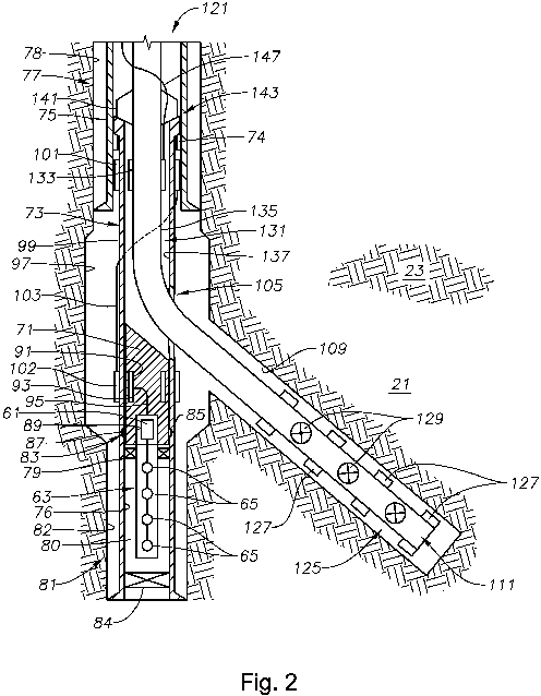
positioning an acoustic assembly (63) within a first wellbore (78) adjacent the zone
of interest (21) in a reservoir (23), the first wellbore (78) drilled within a portion
of the reservoir (23) to receive a hydraulic fracturing treatment defining the zone
of interest (21), the acoustic assembly (63) including an acoustic receiver controller
(61) and a set of one or more acoustic sensors (65) to capture fracture events within
the zone of interest (21);
inserting a drilling deflector (71) into the first wellbore (78);
drilling a second wellbore (109) to receive a fracturing fluid;
positioning a communication conduit bypass (101, 133; 103; 102, 93) within the first
wellbore (78) to extend from a first location above an interface with the second wellbore
(109) to a second location below the interface with the second wellbore (109);
inductively coupling the acoustic receiver controller (61) to a first inductive coupler
(102) connected to a first end of the communication conduit bypass (101, 133; 103;
102, 93), the first inductive coupler (102) positioned adjacent the second location
below the lateral aperture (105);
inductively coupling surface equipment (31, 38) to a second inductive coupler (101)
connected to a second opposite end of the communication conduit bypass (101, 133;
103; 102, 93), the second inductive coupler (101) positioned adjacent the first location
above the lateral aperture (105); and
communicating real-time microseismic event data to a surface unit (31), the microseismic
event data describing microseismic events detected by the acoustic assembly (63) when
performing hydraulic fracturing of the reservoir (23) in the zone of interest (21)
through the second wellbore (109).
|
|
