|
(11) | EP 2 806 656 B1 |

| (12) | EUROPEAN PATENT SPECIFICATION |
|
|
| (54) |
Loudspeaker heat control with state observation Lautsprecherwärmeregelung mit Statusbeobachtung Régulation thermique de haut-parleur avec observation d'état |
|
|
||||||||||||||||||||||||||||
| Note: Within nine months from the publication of the mention of the grant of the European patent, any person may give notice to the European Patent Office of opposition to the European patent granted. Notice of opposition shall be filed in a written reasoned statement. It shall not be deemed to have been filed until the opposition fee has been paid. (Art. 99(1) European Patent Convention). |
[0001] This invention relates to loudspeakers, and in particular, but without limitation, to compact loudspeakers suitable for use in mobile telephones and the like. More particularly, this invention relates to a method and apparatus for monitoring and/or controlling the temperature of loudspeakers.
[0002] Loudspeakers are transducers that convert an electrical signal into sound waves. In most loudspeakers, the transduction of electrical energy into acoustic energy, that is to say the sound waves, is relatively inefficient, typically less than 5% for usual direct-radiator loudspeakers, as used in the mobile phone industry. To obtain high sound pressure levels, high electric power levels must be applied, but since about 95% to 99% of the input energy is converted into heat in the voice-coil, loudspeakers tend to heat up in use.
[0003] Most of the heat can be dissipated to the local surroundings (usually the surrounding air) by radiation and convection: the rate of heat dissipation being closely related to the size, and in particular, to the surface area, of the loudspeaker. As the size of the loudspeaker is reduced, as in the case of a mobile phone's loudspeaker, the maximum achievable sound pressure level is limited by the rate of heat loss because smaller loudspeakers have proportionately less efficient heat dissipation properties compared with larger loudspeakers. The overheating of the voice-coil is one of the main causes of damage and faults in loudspeakers.
[0004] In addition, a smaller loudspeaker requires proportionately higher cone displacements to achieve the same output sound pressure as a larger loudspeaker. Increased cone displacements can lead to undesirable changes in the performance of the loudspeaker, which can ultimately lead to its failure. From the foregoing, therefore, it will be appreciated that the miniaturisation of loudspeakers introduces a number of design considerations that can affect the performance and durability of the loudspeaker.
[0005] In order to achieve competitive sound pressure levels on small or flat loudspeakers, as used in modern mobile telephones, over-driving of the loudspeaker becomes a necessity. In order to minimise or prevent damage to the loudspeaker's voice-coil by overheating or mechanical fatigue, Active Heat Control (AHC) is necessary.
[0006] AHC involves monitoring the voice-coil temperature and then adapting the amplification rate accordingly. In most situations, the direct observation of the voice-coil temperature is not possible, and so indirect observation techniques are required. The voice-coil temperature can be monitored indirectly, for example, by monitoring an observable parameter having a known relationship to the voice-coil's temperature. In many cases, the voice-coil temperature, T, is indirectly observable via the DC resistance, Re, of the loudspeaker by any of the following known expressions:
[0007] The DC resistance, Re, can be measured from the voltage, v(t), and the current, i(t), at the loudspeaker terminals. Since it is not possible to operate on DC signals with A/D convertors, indirect measurement is again necessary, and so it is known to use an additional signal probe at ∼5Hz, although in the invention, any low frequency probe signal can be used, typically, around 20Hz, such that a relationship between the voice coil temperature and the impedance is validly maintained. The probe frequency should be low enough to limit interference with audio signals, but because demodulation is used at the end, very low frequencies (e.g. 1-5 Hz) can become difficult to use in fixed point arithmetic. As such, a probe frequency of about 20Hz has been found to provide a useful and practical compromise.
[0008] It is also known to evaluate a spectrogram for both the voltage and the current during the operation of the loudspeaker, with music or speech signal playing with and without the probe signal applied. The ratio of one spectrogram to the other yields an impedance spectrum Z(f) = U(f)/I(f), from which an exponential average impedance spectrum can then be calculated, considering the current Z(f) in the update process only for spectrum bands with significant energy. Then, the frequency of the system resonance is determined (by looking for the maximum of the magnitude impedance spectrum) and the real part of Z(f) is averaged in the spectral range below the system resonance frequency. Alternatively, a normalised, least means squared algorithm can then be applied to the signal path between the voltage and the current signals (possibly down-sampled, for instance, at a rate of 20:1) during the operation of the loudspeaker, with music or speech signal playing with or without probe signal. The resulting filter models the impedance of the loudspeaker, with a filter length set to, say, 180ms. A set of five parameters originating from a simple physical model is optimized in order to fit (with a spectral least quadratic error criterion) the observed magnitude impedance spectrum |Z(f)|. The DC resistance, Re, is finally extracted from those physical model parameters by simple evaluation of the model spectrum at DC.
[0009] Thermal control and/or protection of the loudspeaker can therefore be achieved by the application of a variable gain to the signal driving the loudspeaker. In most cases, this is applied via a feedback loop derived from the indirectly-observed voice-coil temperature such that the higher the observed temperature, the greater the attenuation of the driving signal. Typically, the variable gain is applied proportionally above a threshold value, such that when the observed voice-coil temperature is below the threshold value, no attenuation is applied, but if the observed voice-coil temperature exceeds the threshold value, the rate of application of the variable gain follows a "controlling law", such as:
[0010] In fact, the application of a variable gain is more complex than this, but in any event, the controlling law attempts to force the temperature of the voice-coil back below the threshold temperature by applying an increasingly negative gain (in dB) to the driving signal until the temperature has returned to its limiting threshold value. Alternatively, a more sophisticated solution involves applying the feedback loop to the compression rate of a Dynamic Range Controller (DRC): the variable gain, in which case, depending on both the estimated voice-coil temperature and the estimated signal envelope.
[0011] Existing loudspeaker temperature control mechanisms, such as those described above, suffer from a number of practical problems:
[0012] Firstly, even assuming that the estimation of the voice-coil temperature is reliable, adaptive gain attenuation of the driving signal, when it is based on an estimation of the voice-coil temperature alone, may introduce unpleasant audio artefacts, such as pumping; and secondly, the complete signal (or frequency band in the case of a multi-band approach) is influenced by the gain control, even the lower-amplitude segments that do not cause thermal heating of the voice-coil.
[0013] As such, the known estimation of the voice-coil temperature is either: not fully reliable; or is only available from the control system with a significant delay. In general, a compromise needs to be struck between high estimate reliability (that is to say, signal-to-noise ratio for the temperature signal) and low delay (latency), but the introduction of a delay in the control feedback loop is known to cause damped or un-damped oscillations.
[0014] In particular, where a voice-coil temperature sensing solution is based on a low-power and transparent probe signal at 20Hz, reliability is achievable only with a long integration time and the where estimated voice-coil temperature is available with a latency of 1s. The use of a feedback loop, as in known in the prior art, may introduce oscillation of the compression ratio parameter at a rate of 1Hz, which causes unpleasant audio artefacts.
[0015] Published US patent application No: US2013/083928 A1 describes a speaker temperature control in which a sequence of estimated temperatures are computed, using a speaker thermal model, as a function of an audio signal that is driving the speaker. In addition, a sequence of attenuation values are computed, as a function of the estimated temperatures sequence, using an excess variable. The excess variable is defined as a difference between an estimated temperature and a thermal limit of the speaker. The audio signal is then attenuated in accordance with the sequence of attenuation values.
[0016] The paper: "Complete Thermal Protection of an Active Loudspeaker" by Chapman P (XP040371441) describes at chapter 6, and in Figure 17, an active heat controller for a loudspeaker utilising a thermal model which provides an estimate for the temperature of a bass speaker, and a gain control, which attenuates speaker to regulate its temperature.
[0017] None of the known solutions take into account the ambient air temperature, but this is, in practice, an important consideration because the ability of the loudspeaker to dissipate heat accumulated in the voice-coil is naturally greater when the air temperature is lower. Put another way, in existing systems, an error factor needs to be built in such that the signal attenuation is overestimated to err on the side of caution. The result is an adequate attenuation at relatively high ambient temperatures, at the expense of over-attenuation in cold ambient environments.
[0018] It is therefore an object of the invention to address one or more of the aforementioned problems, and in particular: noise and unpleasant audio artefacts caused by the voice-coil temperature being estimated with a low reliability; oscillation and unpleasant audio artefacts caused by the voice-coil temperature estimate being delayed; and unnecessary signal processing as a result of a lack of dependency on the actual ambient air temperature.
[0019] According to the invention, there is provided an Active Heat Controller suitable for controlling the temperature of a loudspeaker connected to it, the Active Heat Controller comprising a Dynamic Range Controller intended to be operatively interposed, in use, between an input driving signal terminal of the loudspeaker and the terminals of a voice-coil of the loudspeaker, the Dynamic Range Controller being configured to variably attenuate an input driving signal and to provide the attenuated signal as an output at the voice-coil's terminals, the Active Heat Controller comprising: a probe intended to be operatively connected, and being adapted to provide a probe signal, to the terminals of the loudspeaker's voice-coil for estimating an instantaneous temperature of the voice-coil and the Active Heat Controller being characterised by: a state observer for estimating, on the basis of a thermal model and the voice coil temperature, an instantaneous temperature of a magnet of the loudspeaker; and means for controlling an instantaneous attenuation provided by the Dynamic Range Controller in response to the estimated voice-coil and magnet temperatures; and wherein the state observer compares the heat input with a heat output of the loudspeaker to yield a value reflecting the heat flux of the loudspeaker, the temperature (T) of the voice-coil is in relation to the heat input to the loudspeaker and the heat output of the loudspeaker's magnet is based on a thermal model and uses the estimated voice-coil temperature (Tm) as an input parameter, the difference in heat input and heat output being indicative of the loudspeaker's temperature state being rising or falling. Suitably, the invention provides an Active Heat Controller (AHC) that changes the attenuation of the driving signal applied to the loudspeaker's voice-coil terminals in response to the instantaneous temperature of the voice-coil and a parameter that is indicative of the temperature of the speaker's surroundings, that is to say, the temperature of the loudspeaker's magnet, which varies relatively slowly over time. Suitably, the invention overcomes the problem of over-attenuation of the driving signal in cold environments because the ambient temperature is used to modify the DRC's parameters, as well as the voice-coil temperature. Thus, in cold environments, where heat dissipation by convention and/or conduction is relatively higher, the temperature of the magnet will naturally be relatively lower, and hence the AHC of the invention may act to reduce the amount of DRC attenuation, which may also be, the amount of signal processing required.
[0020] Such a configuration may improve the sound quality of the loudspeaker, and/or alleviate adverse audio artefacts, such as distortion, un-damped oscillation and/or pumping, and/or reduce the signal processing demand on the DRC.
[0021] The temperature of the voice-coil is estimated using a probe signal applied to the loudspeaker, which probe signal suitably yields an output related to the loudspeaker's DC resistance. Suitably, the loudspeaker's DC resistance is related to its voice-coil temperature, thus enabling the voice-coil's temperature to be estimated using the probe.
[0022] The state observer is used to estimate the temperature of the loudspeaker's magnet. The magnet's temperatures typically varies slowly over time, and is in any event indicative of the ambient temperature by virtue of the fact that the rate of heat dissipation from the loudspeaker depends on the ambient temperature. Thus, the magnet of a loudspeaker in a cold environment will cool more quickly for a given thermal input that in a warmer environment with the same thermal input.
[0023] The means for controlling the instantaneous attenuation of the Dynamic Range Controller in response to the estimated voice-coil and magnet temperatures suitably translates the voice-coil and loudspeaker magnet temperature estimates into DRC parameters. This is suitably performed in a translator, which serves to limit the driving signal such that the temperature of the voice-coil is maintained below a desired upper threshold temperature.
[0024] The state observer compares the heat input with the heat output to yield a value reflecting the heat flux of the loudspeaker. More specifically, the state observer monitors the heat input, that is to say the temperature of the voice-coil, and estimates the heat output based on a thermal model for the loudspeaker's magnet using the voice-coil temperature as an input parameter, to determine whether the loudspeaker's temperature is likely to rise or fall at any particular time. The rising or falling temperature state observed can then be passed into a translator, which shapes the parameters for the DRC, or the magnitude of the attenuation (weight) of the DRC, to maintain the loudspeaker's temperature below an upper threshold value. For example, in the case that the loudspeaker is determined to be in a falling temperature state, a weight of 0 can be applied to the DRC meaning that no temperature-regulating attenuation is applied. On the other hand, where the loudspeaker is determined to be in a rising temperature state, a finite weighting can be applied to the DRC meaning that a finite temperature-regulating attenuation is applied. The application of the weighting is suitably determined by the translator, which can apply a linear or non-linear weighting in response to the observed state of the loudspeaker.
[0025] Preferred embodiments of the invention shall now be described, by way of example only, with reference to the accompanying drawings in which:
Figure 1 is a representation of the known Zuccatti-Button thermal model of the loudspeaker;
Figure 2 is a schematic of a multiband DRC;
Figure 3 is a schematic block diagram for an AHC in accordance with the invention; and
Figure 4 is a schematic diagram of an example an AHC in accordance with the invention with two-segment parameterisation.
[0026] Referring to Figure 1, the Zuccati-Button thermal model of a loudspeaker (cf. Thermal Parameters and Power Ratings of Loudspeakers, C. Zuccatti, JAES Volume 38 Issue 1/2 pp. 34-39; February 1990) explains the dynamic of the voice-coil temperature, T(t), as a mass-spring system operating on the temperature difference T(t) - Tm(t), where Tm(t) represents the temperature of the loudspeaker magnet. Assuming that the magnet temperature, Tm(t), is known and constant, then simple considerations show that the voice coil temperature, T(t), is bounded by Tmax if the driving power, r(t), that is, the power produced by the voice-coil, is also bounded, as follows:
[0027] This model suggests that an-efficient temperature control strategy for limiting the voice-coil temperature involves applying a variable gain to the incoming signal (for example, by modulating the compression rate of a DRC) to ensure the bounding of r(t) by:
[0028] In all known thermal control solutions, the control strategy is open loop so that the control law does not need to monitor the voice-coil temperature.
[0029] The invention is based, in one aspect, on the fact although the temperature of the loudspeaker's magnet is not directly observable, assuming the parameters of the thermal model are known, the magnet's temperature can be tracked by the state observer from the measurements of the voice-coil temperature. This can be accomplished because the magnet, in most practical situations, is thermally coupled to the voice-coil, and so it is possible to estimate the magnet's temperature if the voice-coil's temperature over time is known, and the thermal parameters (thermal coupling of the voice-coil to the magnet and the dissipation of heat from the magnet) of the system are known also. Experiments have shown that the rate of change of the magnet's temperature is usually several orders of magnitude slower than that of the voice-coil, typically at least 100 times slower in experiments. Therefore, the AHC of the invention makes use of the reasonable assumption that the temperature of the magnet over time, Tm(t), is almost constant over the time-frame of the control parameters, therefore justifying the use of open-loop system.
[0030] The Zuccati-Button thermal model, as shown in Figure 1, describes the dynamic of the voice-coil temperature, T, as a linear dynamic system, in which:
[0031] Where
is the column state vector, C and Y are respectively the thermal capacity and thermal impedance matrices, r is the power produced by the voice-coil and T, Tm and Ta are respectively the voice-coil, magnetic and ambient air temperatures.
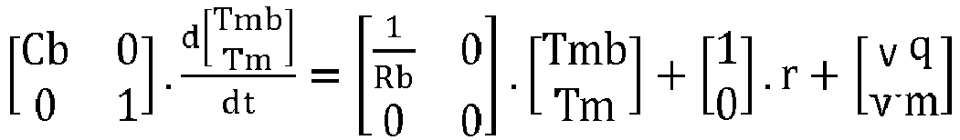
[0032] The geometric vector notation is adopted for Tmb and Tam, i.e. Tmb is, by definition, T - Tm and Tam is, by definition, Tm - Ta. Finally, the parameterisation of the model involves the thermal resistances Rb and Rm and the thermal capacities Cb and Cm:
[0033] Accepted principles indicate that the time constant of the magnetic system, Rm.Cm, is several orders slower than the time constant of the voice-coil system, τ=Rb*Cb, which is backed-up by laboratory measurements on actual mobile phone loudspeakers, which give Rb.Cb values of about 1s, whereas Rm.Cm values are several minutes. It is therefore well-founded to uncouple the voice-coil system from the magnetic system, and to consider the voice-coil system only, with Tm being now an unknown slow-varying random walk (NB: Tm integrates the slow dynamic from Tam and the unknown dynamic from Ta, which is also assumed relatively slow).
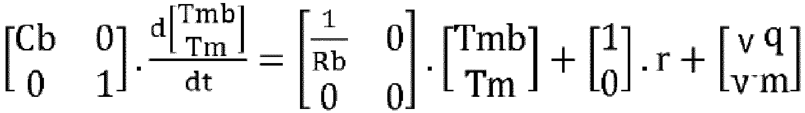
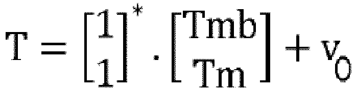
where
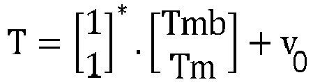
is the new state vector, vq, a Gaussian noise representing the uncertainty of the voice-coil model, vm, a Gaussian noise representing the seed of the random walk from Tm and vo, the measurement noise on the voice-coil temperature. This dynamic system, represented by the above equations, is a simplified version of the Zuccati-Button model where most of its unreliable parameters (Rm and Cm are known to be dependant from the type of stimulus applied to the loudspeaker), are replaced by a stochastic model. However, if the statistics of the noise elements and the model of the parameter are both known, then it is possible to generate a state observer that computes the best estimate of the hidden state,
given r and the observation of T. As a side-effect, the state observer regenerates an optimal estimation of the voice-coil temperature through
that can be used in further calculations. The dynamic system of the voice-coil temperature is as follows:
[0034] If a constant power r∞ is applied, then the voice-coil temperature finally reaches an asymptotic temperature T∞:
because if we assume that it exists a time t for which Tmb(t) is greater than Rb . r∞, then, by continuity of the solution Tmb(t), there exists a point where the function for Tmb(t) crosses Rb . r∞. Thus, at that time, the function derivative
is negative: the only possibility for Tmb(t) to cross Rb . r∞ is with a negative slope, forbidding the function from passing from the domain Tmb(t) < Rb . r∞ to its complementary domain. In other words, once Tmb(t) is lower than Rb . r∞, it remains lower than Rb . r∞ at any subsequent time.
[0035] The interpretation of:
is that that the dissipating heat flux in:
is proportional to the temperature gradient relative to Tm. Therefore, the larger this gradient, the larger the dissipating heat flux. Conversely, the incoming heat flux is due exclusively to the applied power r. Thus, heat in the voice-coil is accumulated and increases its temperature, T, until the dissipation heat flux balances the incoming heat flux. Balance is achieved when the gradient Tmb(t) has reached Rb.r. The condition: Tmb(t) < Rb. r∞ justifies the open-loop control and can be recast as follows:
[0036] If an estimation of the slow-varying magnetic temperature, Tm, is available from the state observer operating on:
then it is enough to limit the feeding power by
(Tmax - Tm) in order to ensure that T(t) is below Tmax at all times, thus achieving the heat control process of the invention.
[0037] An example of an AHC in accordance with the invention is described below with reference to Figures 2 and 3 of the drawings. In this exemplary embodiment of the invention, the AHC applies a variable gain to the audio signal, measures the voice-coil temperature, provides an estimate of the slow varying magnetic temperature, given the measurements of the voice-coil temperature, and then translates the magnetic temperature estimates into compression parameters.
[0038] In Figure 2, an Active Heat Controller (AHC) 10 for a loudspeaker 12 comprises a Dynamic Range Controller (DRC) 14 interposed between an audio input signal 16 and the loudspeaker 12. The DRC 14 comprises an attenuator 18 that can reduce the magnitude of the audio input signal 16 so that the loudspeaker 12 does not overheat in use. The output 20 of the DRC 14 passes through a digital-to-analogue converter 22, before being amplified 24 and passed to the terminals 26 of the loudspeaker 12. The output 20 of the DRC 14 is overlaid with a 20Hz probe signal 28, which is fed to the loudspeaker 12 also.
[0039] The attenuator 18 of the DRC 14 is controlled in a known manner by an analyser by different amounts over different amplitude ranges. This is achieved, in a known manner by an envelope follower 30 and a gain processor 32 which operates between a linear-to-logaritmic 34 and a logarithmic-to-linear 36 converter. The gain processor 32 thus adjusts the attenuator 18,. The envelope follower 30 is also connected to an output of the parameter estimator 51 because the envelope follower 30 aims to estimate the power r from the source signal 16, which estimate is based on the system impedance.
[0040] In fact, the gain control of the DRC, the output of the gain processor 32 uses a table similar to that shown in Figure 4, an illustration of a compression curve with a so-called "hard-knee" shape, i.e. resulting from a piece-wise affine function. Other possibilities exist for the compression curves, such as a "soft-knee" curve, which can be used in order to smooth the compression curve.
[0041] The application of a DRC as a variable gain can be as simple as that illustrated in Figure 3, but more evolved schemes exist. For instance, a multi-band DRC can be applied to the signal, with one DRC channel allocated for the loudspeaker resonance and a second channel for the rest of the spectrum. The attenuator 18 is then implemented respectively either as a variable parametric equalizer configured as band pass centred on the resonant frequency or as a complementary filter.. Separate compression setting and weight application are possible.
[0042] The invention 10, however, additionally comprises a weighting module 38 that multiplies the output of the gain processor 32 by a value ranging from 0 to 1, thus overriding the attenuation setting of the DRC. When the estimated magnet temperature Tm (output port of 40) is below a predefined threshold, the weighting module applies a weighting of 0 to the gain processor 32 thus deactivating the DRC 14. However, when the estimated magnet temperature (output port of 40) exceeds the predefined threshold value, Tmax, the weighting increases to a finite value thus overriding the gain processor's setting 32, which relatively under-drives the loudspeaker 12 by over-attenuating the output signal 20 at the output of the DRC 14, thus allowing the loudspeaker 12 to cool.
[0043] Figure 2 is a schematic of the multiband DRC, which is represented by block 14 in Figure 2. In the multiband DRC, there is a variable attenuator 18 whose gain is controlled by an analyser as described herein, which maps the input audio signal 16 to an attenuated signal by different amounts over different frequency and amplitude ranges.
[0044] In the illustrated multiband DRC 14, this is achieved by an envelope follower 30 and a number (in this case, a pair of) gain processors 32, 32a which operate between a linear-to-logarithmic 34 and a logarithmic-to-linear 36 converter.
[0045] The first gain processor 32 provides an output that is fed to a first weighting module 38 that multiplies the output of the gain processor 32 by a value ranging from 0 to 1, thus overriding the default attenuation setting of the DRC. The weighting module also receives an input from the translator 46 before outputting a first gain modification to a pre-equaliser 70, which is also connected to a low impedance estimation signal outputted from the parameter estimator 51. The pre-equaliser 70 output signal feeds into the probe signal 28.
[0046] Meanwhile, a second signal processor acts on a different portion of the linear-to-logarithmic converted signal via a second gain processor 32a. The output of the second gain processor 32a is fed to a second weighting module 38a, which also multiplies the output by a value ranging from 0 to 1, as determined by the translator 46. The output of the second weighting module is fed, via a logarithmic-to-linear converter 36a directly to the attenuator 18 of the DRC 14. Thus, the multiband DRC is able to modify the gain using two sets of parameters simultaneously.
[0047] The invention is predicated on knowing the instantaneous state of the loudspeaker, that is to say the thermal flux being the heat input, the heat output and hence whether the temperature of the voice-coil is likely to continue increasing, or remain in a steady-state condition whereby the thermal input balances the thermal output of the loudspeaker 12.
[0048] This is accomplished by a state observer 40, which determines the thermal state of the loudspeaker 12 during use.
[0049] The state observer monitors DC resistance of the loudspeaker's 12 voice-coil, which is indicative of the voice-coil's temperature. This is accomplished by applying the probe signal 28, the level of the probe signal 28 being chosen so that it does not interfere with the music or speech signal. It has been found that a sinusoidal probe signal at 20Hz, and -60dBFS is substantially transparent for music and speech signals, although different algorithms are possible in order to evaluate the impedance from the probe signal.
[0050] In Figure 3, the probe 28 applies a signal on top of an output signal 20 of the DRC 14, and a first analogue-to-digital converter 45 connected to the terminals 26 of the loudspeaker 12 is provided for measuring the probe signal voltage across the loudspeaker terminals 26. A second analogue-to-digital converter 47 connected in parallel to a resistor 49 wired in series across the terminals 26 of the loudspeaker 12, which is used for measuring the probe signal current in the loudspeaker 12. A parameter estimator 51 is operatively connected to the analogue-to-digital converters 47, 49 for calculating the DC resistance of the loudspeaker 12 based on the probe signal's voltage and current, the DC resistance being indicative of the loudspeaker's voice-coil temperature.
[0051] One solution consists in applying a succession of resonant filters tuned at the probe frequency and down-samplers to both the voltage and the current signals. The resulting signal, sampled at a very low frequency (e.g. 300 Hz), is finally demodulated, for instance with a discrete Teager operator, resulting in an envelope that is turned into a dB or logarithmic scale. The level difference between both envelops, in the dB or logarithmic domain, is an image of the loudspeaker resistance at 20Hz.
[0052] There is a trade-off here between acceptable SNR and acceptable latency. Indeed, the sharper the resonant filters, the better the SNR, but at the same time, the group delay of the filters increases, adding latency.
[0053] Nevertheless, and somewhat surprisingly, it has been found that this feedback loop, contrary to accepted wisdom in the art, does not happen at the audio rate: the dynamic of this feedback loop being that of the loudspeaker's magnet, which is on the order of minutes added to those of the ambient air temperature, which is also assumed to be slow. Therefore, considering both the audio rate (e.g. 48kHz) and the DRC control rate (e.g. 300Hz), the evolution of the thermal parameters (magnetic temperature) is almost imperceptible, a latency of several seconds is even not significant and SNR can be set arbitrary high.
[0054] The impedance and voice-coil temperature (the building block parameter estimation) can thus be estimated with a voltage directly sensed from the terminals of the loudspeaker (direct v-sensing). However, indirect v-sensing is possible instead by processing in the digital domain the signal sent to the DAC 22.
[0055] The construction of state observer is, in principle, straightforward but nevertheless technical. An example of the different steps required for the construction of a quadratic optimal observer (Kalman filter) is summarised below, but it will be readily apparent that many variations are possible and it is not possible to list all of those herein.
[0056] Obtaining a discrete model is the first necessary task. The bilinear transform is a popular scheme that preserves most of the spectral properties of the system. Formally, it consists in substituting the Laplace variable s:
where Ts represents the sampling rate and z the discrete shift operator. If the original continuous-time system was described with the state-space matrices (A,B,C,D), then the state-space matrices of the discrete system, (Phi, Gamma, H, J), are given by:
where the operation inv() represents the matrix inversion, the matrix I represents the identity matrix. In the present example, the transformation of the stochastic thermal model results in a second order linear system, in which the form of a linear quadratic estimator is usually:
where T[k] represents the current voice-coil measurement, r[k] the current feeding power estimate, e[k|k] the prediction error, x[k+1|k] the predicted state (i.e. the prediction of the state at time k+1, given the observation up to time k) and x[k|k] the estimated state. Kf and Kp are respectively the Kalman filter and predictor gains (they are both matrices). The Kalman gains represent a sort of weight or trade-off between the confidence of the observation and the confidence the state estimate. In its asymptotic form, those weights are constant; so the Kalman gains are. A more general form includes a time variation of the Kalman gains, illustrating the fact that initially, the confidence of the state estimate is very poor, but confidence grows gradually as more observations become available. In practical cases, the Kalman gains reach their asymptotic limits after a few seconds. Therefore, the actual observer can tabulate the first values of the Kalman gains and switch to constant gains after a while. A predictive model, interpolation, re-sampling are alternate solutions for the tabulation of the Kalman gains. Actually, any kind of approximation for the Kalman gains is usually suitable, resulting only in a moderate loss of performance.
[0057] Finally, the constructed state observer 40 uses a measurement of T and the estimation of r as inputs and generates an estimation of Tm, which is based on a thermal model 42 of the loudspeaker 12. As stated earlier, the measurement of T usually involves a latency which must be compensated by a synchronization delay 50 in the estimation of r. The operation rate of the state observer, Ts, is dictated by the spectral characteristics of the thermal system (typically a few Hz). However, it has been found to be simpler to operate the state observer at a higher rate, synchronous to the rate of control of the DRC, which is still low and acceptable for complexity purposes.
[0058] The output of the state observer 40 feeds into a translator 46, which modulates the threshold g = [r0] of the DRC compression curve, while the rest of the compression curve is configured with two segments as a brick-wall (i.e. with c = [0,1], cf. Figure 4). A slightly different translation is possible with a constant compression threshold g = [r0] but with the weight, wm, modulated as follows:
and still a compression curve configured as a brick-wall (i.e. with c = [0,1], cf. Figure 4). This translation ensures that the feeding power r verifies (when Tm is in the interval [Tmmin, Tmmax]) the following condition:
[0059] The additional degree of freedom (the parameters r0 and Tmmin are related together, which relationship is used for trading smoothness against loudness. On the one hand, when Tmmin is far from Tmmax, smoothness in the variation of the DRC parameters is maximized, limiting therefore transient artefacts. On the other hand, the higher the threshold r0 is, the less the signal is compressed resulting in a loudness which is less processed.
[0060] The invention has every advantage of known systems, but without their limitations. Indeed, the control strategy of the invention is (mainly) open-loop, therefore oscillation of the control parameters is not possible. The dynamic of the magnetic temperature, Tm(t), is very slow (in laboratory measurements, the half-life duration of the magnetic system was greater than 3 minutes); so this temperature can be reliably estimated despite unfavourable SNR ratio on the voice-coil because long integration time generates latency durations that are not significant relative to the time parameters of the magnetic system. Finally, the signal processing effort is greater when the magnetic temperature, Tm(t), is high, which can happen either because the loudspeaker has been exposed to a long heating stimulus or because the ambient air is hot. Said differently, the thermal control system described in this invention applies moderate signal dynamic compression when the ambient air is cold or when the loudspeaker has not been exposed to a long heating stimulus. In short, this invention is in general more transparent and produces less audio artefacts than any other solution.
1. An Active Heat Controller (10) suitable for controlling the temperature of a loudspeaker
(12) connected to it, the Active Heat Controller (10) comprising a Dynamic Range Controller
(14) operatively interposed between an input driving signal terminal (16) for the
loudspeaker (12) and the terminals (26) of a voice-coil of the loudspeaker (12), the
Dynamic Range Controller (14) being configured to variably attenuate an input driving
signal and to provide the attenuated signal as an output at the voice-coil's terminals
(20), the Active Heat Controller (10) comprising: a probe (28) operatively connected,
and being adapted to provide a probe signal, to the terminals (26) of the loudspeaker's
voice-coil (12) for estimating an instantaneous temperature of the voice-coil and
the Active Heat Controller being characterised by: a state observer (40) for estimating, on the basis of a thermal model and the voice
coil temperature, an instantaneous temperature of a magnet of the loudspeaker (12);
and means (38) for controlling an instantaneous attenuation provided by the Dynamic
Range Controller (14) in response to the estimated voice-coil and magnet temperatures;
and wherein the state observer (40) compares the heat input with a heat output of
the loudspeaker to yield a value reflecting the heat flux of the loudspeaker, the
temperature (T) of the voice-coil is in relation to the heat input to the loudspeaker
(12) and the heat output of the loudspeaker's magnet is based on the thermal model
(42) and uses the estimated voice-coil temperature (Tm) as an input parameter, the
difference in heat input and heat output being indicative of the loudspeaker's temperature
state being rising or falling.
2. An Active Heat Controller (10) as claimed in claim 1, wherein the probe is adapted
to overlay a probe signal to the output (20) of the Dynamic Range Controller (14),
which probe signal is also fed to the loudspeaker (12), and wherein the Active Heat
Controller comprises a first analogue-to-digital converter (45) connected to the terminals
(26) of the loudspeaker (12) for measuring the probe signal voltage across the loudspeaker
terminals (26) and a second analogue-to-digital converter (47) connected in parallel
to a resistor (49) wired in series across the terminals (26) of the loudspeaker (12)
adapted to measure the probe signal current in the loudspeaker (12), and a parameter
estimator (51) operatively connected to the analogue-to-digital converters (47, 49)
adapted to calculate the DC resistance of the loudspeaker based on the probe signal's
voltage and current, the DC resistance being indicative of the loudspeaker's voice-coil
temperature.
3. An Active Heat Controller (10) as claimed in claim 2, wherein the state observer (40)
is operatively connected to the parameter estimator (51) and the Active Heat Controller
(10) comprises estimating means adapted to estimate the temperature of the loudspeaker's
magnet (12) using a thermal model (42) of the loudspeaker (12) applied to the measured
voice-coil temperature (T).
4. An Active Heat Controller (10) as claimed in claim 3, wherein the thermal model (42)
comprises thermal parameters of the loudspeaker, the thermal parameters being any
one or more of the group comprising: the thermal coupling efficiency of the voice-coil
to the magnet; the thermal conductivity of the magnet; and the temperature-dependent
heat dissipation rate of the magnet.
5. An Active Heat Controller (10) as claimed in any preceding claim, wherein the state
observer (40) comprises an estimating means adapted to estimate the temperature of
the loudspeaker's magnet (12) using a thermal model (42) of the loudspeaker (12) applied
to the measured voice-coil temperature (T), the thermal model being a Zuccati-Button
thermal model for the loudspeaker (12).
6. An Active Heat Controller (10) as claimed in any preceding claim, wherein the state
observer (40) comprises an estimating means adapted to estimate the temperature of
the loudspeaker's magnet (12) using a thermal model (42) of the loudspeaker (12) applied
to the measured voice-coil temperature (T), the thermal model being a bilinear transform
of the equations:
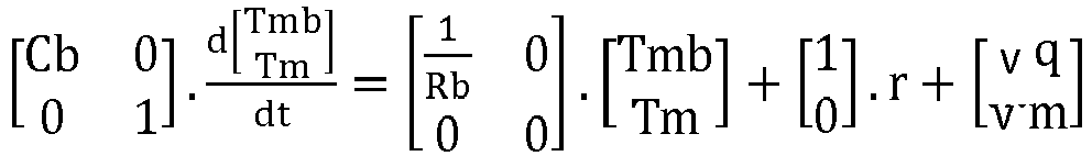
and
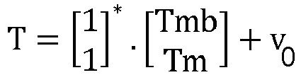
wherein: Tmb is T-Tm; Tm is the magnet temperature; Rb is thermal resistance; r is the power produced by the voice-coil and T, Tm and Ta are respectively the voice-coil, magnetic and ambient air temperatures; where vq and vm are weightings; and wherein v is a vector.
and
wherein: Tmb is T-Tm; Tm is the magnet temperature; Rb is thermal resistance; r is the power produced by the voice-coil and T, Tm and Ta are respectively the voice-coil, magnetic and ambient air temperatures; where vq and vm are weightings; and wherein v is a vector.
7. An Active Heat Controller (10) as claimed in any preceding claim, further comprising
a translator (46) adapted to limit the driving signal such that the temperature of
the voice-coil is maintained below a desired upper threshold temperature, the translator
(46) being operatively connected to the means (38) for controlling the instantaneous
attenuation of the Dynamic Range Controller (14) in response to the estimated voice-coil
(T) and magnet temperatures (Tm).
8. An Active Heat Controller (10) as claimed in claim 7, wherein the translator (46)
controls a weighting module (38) for weighting the magnitude of the attenuation of
the Dynamic Range Controller (14).
9. An Active Heat Controller (10) as claimed in claim 8, wherein when the state observer
(40) determines that the loudspeaker (12) is in a falling temperature state, a weighting
applied by the weighting module (38) of 0 can be applied to the Dynamic Range Controller
(14).
10. An Active Heat Controller (10) as claimed in claim 8 or claim 9, wherein when the
state observer (40) determines that the loudspeaker (12) is in a rising temperature
state, a finite weighting is applied by the weighting module (38) to the Dynamic Range
Controller (14).
11. An Active Heat Controller (10) as claimed in claim 9, claim 10 or claim 11, wherein
the translator (46), applies a linear or non-linear weighting by the weighting module
(38) in response to the observed state of the loudspeaker (12).
12. An Active Heat Controller (10) as claimed in any preceding claim, wherein the probe
signal (28) comprises a sinusoidal probe signal at substantially 20Hz and substantially
-60dBFS.
1. Aktiver Wärmeregler (10), geeignet zum Regeln der Temperatur eines an ihn angeschlossenen
Lautsprechers (12), wobei der aktive Wärmeregler (10) einen Dynamikbereichsregler
(14) umfasst, der betriebsfähig zwischen einer Treibersignalklemme (16) für den Lautsprecher
(12) und den Klemmen (26) einer Schwingspule des Lautsprechers (12) zwischengeschaltet
ist, wobei der Dynamikbereichsregler (14) ausgestaltet ist, ein Eingangstreibersignal
veränderbar zu dämpfen und das gedämpfte Signal als Ausgabe an den Schwingspulenklemmen
(20) bereitzustellen, wobei der aktive Wärmeregler (10) umfasst: eine Sonde (28),
die betriebsfähig angeschlossen ist, und angepasst ist, den Klemmen (26) der Lautsprecher-Schwingspule
(12) zum Schätzen einer momentanen Temperatur der Schwingspule ein Sondensignal bereitzustellen,
und wobei der aktive Wärmeregler gekennzeichnet ist durch: einen Zustandsbeobachter (40) zum Schätzen, auf Grundlage eines thermischen Modells
und der Schwingspulentemperatur, einer momentanen Temperatur eines Magneten des Lautsprechers
(12); und Mittel (38) zum Regeln einer momentanen Dämpfung, die von dem Dynamikbereichsregler
(14) in Reaktion auf die geschätzte Temperatur der Schwingspule und des Magneten bereitgestellt
wird; und wobei der Zustandsbeobachter (40) die Wärmeeingabe mit einer Wärmeausgabe
des Lautsprechers vergleicht, um einen Wert zu ergeben, der den Wärmefluss des Lautsprechers
wiedergibt, die Temperatur (T) der Schwingspule in Beziehung zur Wärmeeingabe des
Lautsprechers (12) steht und die Wärmeausgabe des Lautsprecher-Magneten auf dem thermischen
Modell (42) basiert und die geschätzte Schwingspulentemperatur (Tm) als Eingangsparameter
verwendet, wobei der Unterschied in der Wärmeeingabe und der Wärmeausgabe indikativ
dafür ist, dass die Lautsprechertemperatur ansteigt oder fällt.
2. Aktiver Wärmeregler (10) nach Anspruch 1, wobei die Sonde angepasst ist, ein Sondensignal
zum Ausgang (20) des Dynamikbereichsreglers (14) zu überlagern, wobei das Sondensignal
auch dem Lautsprecher (12) zugeführt wird, und wobei der aktive Wärmeregler einen
ersten Analog-Digital-Wandler (45) umfasst, der an die Klemmen (26) des Lautsprechers
(12) zum Messen der Sondensignalspannung über die Lautsprecherklemmen (26) angeschlossen
ist, und einen zweiten Analog-Digital-Wandler (47) der mit einem Widerstand (49) parallelgeschaltet
ist, der in Reihe über die Klemmen (26) des Lautsprechers (12) angeschlossen ist,
der angepasst ist, den Sondensignalstrom in dem Lautsprecher (12) zu messen und einen
Parameter-Schätzer (51), der betriebsfähig an die Analog-Digital-Wandler (47, 49)
angeschlossen ist, der angepasst ist, den Gleichstromwiderstand des Lautsprechers
basierend auf der Spannung und dem Strom des Sondensignals zu berechnen, wobei der
Gleichstromwiderstand indikativ für die Schwingspulentemperatur des Lautsprechers
ist.
3. Aktiver Wärmeregler (10) nach Anspruch 2, wobei der Zustandsbeobachter (40) betriebsfähig
an den Parameterschätzer (51) angeschlossen ist, und der aktive Wärmeregler (10) Schätzmittel
umfasst, die angepasst sind, die Temperatur des Lautsprechermagneten (12) unter Verwendung
eines thermischen Modells (42) des Lautsprechers (12), das auf die gemessene Schwingspulentemperatur
(T) angewandt wird, zu schätzen.
4. Aktiver Wärmeregler (10) nach Anspruch 3, wobei das thermische Modell (42) thermische
Parameter des Lautsprechers umfasst, wobei die thermischen Parameter ein beliebiger
oder mehrere Parameter aus der Gruppe ist/sind, die Folgendes umfasst: den thermalen
Kopplungswirkungsgrad der Schwingspule zum Magneten; die thermale Leitfähigkeit des
Magneten; und die temperaturabhängige Wärmeabführungsgeschwindigkeit des Magneten.
5. Aktiver Wärmeregler (10) nach einem der vorhergehenden Ansprüche, wobei der Zustandsbeobachter
(40) ein Schätzmittel umfasst, das angepasst ist, die Temperatur des Lautsprechermagneten
(12) unter Verwendung eines thermischen Modells (42) des Lautsprechers (12) angewandt
auf die gemessene Schwingspulentemperatur (T) zu schätzen, wobei das thermische Modell
für den Lautsprecher (12) ein thermisches Modell nach Zuccati-Button ist.
6. Aktiver Wärmeregler (10) nach einem der vorhergehenden Ansprüche, wobei der Zustandsbeobachter
(40) ein Schätzmittel umfasst, das angepasst ist, die Temperatur des Lautsprechermagneten
(12) unter Verwendung eines thermischen Modells (42) des Lautsprechers (12) angewandt
auf die gemessene Schwingspulentemperatur (T) zu schätzen, wobei das thermische Modell
eine bilineare Transformation folgender Gleichungen ist:
und
wobei: Tmb gleich T - Tm; Tm die Magnettemperatur ist; Rb der thermische Widerstand ist; r die von der Schwingspule erzeugte Kraft ist, T, Tm und Ta jeweils die Temperatur der Schwingspule, die magnetische und die Umgebungslufttemperatur sind; wobei vq und vm Gewichtungen sind; und wobei v ein Vektor ist.
7. Aktiver Wärmeregler (10) nach an einem der vorhergehenden Ansprüche, überdies umfassend
einen Umsetzer (46), der angepasst ist, das Treibersignal zu begrenzen, so dass die
Temperatur der Schwingspule unter einer gewünschten oberen Schwellentemperatur gehalten
wird, wobei der Umsetzer (46) betriebsfähig an das Mittel (38) zum Regeln der momentanen
Dämpfung des Dynamikbereichsreglers (14) in Reaktion auf die geschätzte Temperatur
der Schwingspule (T) und des Magneten (Tm) angeschlossen ist.
8. Aktiver Wärmeregler (10) nach Anspruch 7, wobei der Umsetzer (46) ein Gewichtungsmodul
(38) zum Gewichten der Stärke der Dämpfung des Dynamikbereichsreglers (14) regelt.
9. Aktiver Wärmeregler (10) nach Anspruch 8, wobei, wenn der Zustandsbeobachter (40)
bestimmt, dass sich der Lautsprecher (12) in einem fallenden Temperaturzustand befindet,
eine von dem Gewichtungsmodul (38) angewandte Gewichtung von 0 auf den Dynamikbereichsregler
(14) angewandt werden kann.
10. Aktiver Wärmeregler (10) nach Anspruch 8 oder 9, wobei, wenn der Zustandsbeobachter
(40) bestimmt, dass sich der Lautsprecher (12) in einem steigenden Temperatursturzzustand
befindet, eine endgültige Gewichtung von dem Gewichtungsmodul (38) auf den Dynamikbereichsregler
(14) angewandt wird.
11. Aktiver Wärmeregler (10) nach Anspruch 9, Anspruch 10, wobei der Umsetzer (46) eine
lineare oder nichtlineare Gewichtung durch das Gewichtungsmodul (38) in Reaktion auf
den beobachteten Zustand des Lautsprechers (12) anwendet.
12. Aktiver Wärmeregler (10) nach einem der vorhergehenden Ansprüche, wobei das Sondensignal
(28) ein sinusförmiges Sondensignal bei im Wesentlichen 20 Hz und im Wesentlichen
-60dBFS umfasst.
1. Régulateur de chaleur actif (10) approprié pour réguler la température d'un haut-parleur
(12) connecté à celui-ci, le régulateur de chaleur actif (10) comprenant un dispositif
de commande de plage dynamique (14) interposé de manière opérationnelle entre une
borne d'un signal de commande d'entrée (16) pour le haut-parleur (12) et les bornes
(26) d'une bobine acoustique du haut-parleur (12), le dispositif de commande de plage
dynamique (14) étant configuré pour atténuer de manière variable un signal de commande
d'entrée et pour fournir le signal atténué en tant que sortie au niveau des bornes
de la bobine acoustique (20), le régulateur de chaleur actif (10) comprenant : une
sonde (28) connectée de manière opérationnelle, et étant adaptée pour fournir un signal
de sonde, aux bornes (26) de la bobine acoustique du haut-parleur (12) pour estimer
une température instantanée de la bobine acoustique et le régulateur de chaleur actif
étant caractérisé par : un observateur d'état (40) permettant d'estimer, sur la base du modèle thermique
et de la température de la bobine acoustique, une température instantanée d'un aimant
du haut-parleur (12) ; et un moyen (38) permettant de commander une atténuation instantanée
fournie par le dispositif de commande de plage dynamique (14) en réponse aux températures
estimées de l'aimant et de la bobine acoustique ; et dans lequel l'observateur d'état
(40) compare l'entrée de chaleur à une sortie de chaleur du haut-parleur pour produire
une valeur reflétant le flux de chaleur du haut-parleur, la température (T) de la
bobine acoustique est relative à l'entrée de chaleur du haut-parleur (12) et la sortie
de chaleur de l'aimant du haut-parleur est basée sur le modèle thermique (42) et utilise
la température (Tm) estimée de la bobine acoustique en tant que paramètre d'entrée,
la différence entre l'entrée de chaleur et la sortie de chaleur étant indicative de
l'état de température du haut-parleur ascendante ou descendante.
2. Régulateur de chaleur actif (10) selon la revendication 1, dans lequel la sonde est
adaptée pour recouvrir un signal de sonde à la sortie (20) du dispositif de commande
de plage dynamique (14), ce signal de sonde est également alimenté vers le haut-parleur
(12), et dans lequel le régulateur de chaleur actif comprend un premier convertisseur
analogique à numérique (45) connecté aux bornes (26) du haut-parleur (12) permettant
de mesurer la tension du signal de sonde à travers les bornes de haut-parleur (26)
et un second convertisseur analogique à numérique (47) connecté en parallèle à une
résistance (49) câblé en série par l'intermédiaire des bornes (26) du haut-parleur
(12) adapté pour mesurer le courant du signal de sonde dans le haut-parleur (12),
et un estimateur de paramètre (51) connecté de manière opérationnelle aux convertisseurs
analogiques à numériques (47, 49) adapté pour calculer la résistance CC du haut-parleur
sur la base de la tension et du courant du signal de sonde, la résistance CC indiquant
la température de la bobine acoustique du haut-parleur.
3. Régulateur de chaleur actif (10) selon la revendication 2, dans lequel l'observateur
d'état (40) est connecté de manière opérationnelle à l'estimateur de paramètre (51)
et le contrôleur de chaleur actif (10) consiste à estimer un moyen adapté pour estimer
la température de l'aimant du haut-parleur (12) à l'aide du modèle thermique (42)
du haut-parleur (12) appliqué à la température (T) mesurée de la bobine acoustique.
4. Régulateur de chaleur actif (10) selon la revendication 3, dans lequel le modèle thermique
(42) comprend des paramètres thermiques du haut-parleur, les paramètres thermiques
étant n'importe lequel ou lesquels parmi le groupe comprenant : l'efficacité de couplage
thermique de la bobine acoustique à l'aimant ; la conductivité thermique de l'aimant
; et le taux de dissipation thermique dépendant de la température de l'aimant.
5. Régulateur de chaleur actif (10) selon l'une quelconque des revendications précédentes,
dans lequel l'observateur d'état (40) comprend un moyen d'estimation adapté pour estimer
la température de l'aimant du haut-parleur (12) à l'aide d'un modèle thermique (42)
du haut-parleur (12) appliqué à la température (T) mesurée de la bobine acoustique,
le modèle thermique étant un modèle thermique de Zuccati-Button pour le haut-parleur
(12).
6. Régulateur de chaleur actif (10) selon l'une quelconque des revendications précédentes,
dans lequel l'observateur d'état (40) comprend un moyen d'estimation adapté pour estimer
la température de l'aimant du haut-parleur (12) à l'aide d'un modèle thermique (42)
du haut-parleur (12) appliqué à la température (T) mesurée de la bobine acoustique,
le modèle thermique constituant une transformée bilinéaire des équations :
et
dans lesquelles : Tmb est T - Tm ; Tm est la température de l'aimant ; Rb est la résistance thermique ; r est la puissance produite par la bobine acoustique et T, Tm et Ta sont respectivement les températures de l'air ambiant, de l'aimant et de la bobine acoustique ; où vq et vm sont des pondérations ; et dans lesquelles v est un vecteur.
7. Régulateur de chaleur actif (10) selon l'une quelconque des revendications précédentes,
comprenant en outre un translateur (46) adapté pour limiter le signal de commande
de telle sorte que la température de la bobine acoustique est maintenue sous une température
de seuil supérieur souhaitée, le translateur (46) étant connecté de manière opérationnelle
au moyen (38) permettant de commander l'atténuation instantanée du dispositif de commande
de plage dynamique (14) en réponse aux températures estimées de l'aimant (Tm) et de
la bobine acoustique (T).
8. Régulateur de chaleur actif (10) selon la revendication 7, dans lequel le translateur
(46) commande un module de pondération (38) permettant de pondérer l'amplitude de
l'atténuation du dispositif de commande de plage dynamique (14).
9. Régulateur de chaleur actif (10) selon la revendication 8, dans lequel lorsque l'observateur
d'état (40) détermine que le haut-parleur (12) se trouve dans un état de température
descendante, une pondération appliquée par le module de pondération (38) de 0 peut
être appliquée au dispositif de commande de plage dynamique (14).
10. Régulateur de chaleur actif (10) selon la revendication 8 ou la revendication 9, dans
lequel lorsque l'observateur d'état (40) détermine que le haut-parleur (12) se trouve
dans un état de température ascendante, une pondération finie est appliquée par le
module de pondération (38) au dispositif de commande de plage dynamique (14).
11. Régulateur de chaleur actif (10) selon la revendication 9, la revendication 10 ou
la revendication 11, dans lequel le translateur (46) applique une pondération linéaire
ou non linéaire par le module de pondération (38) en réponse à l'état observé du haut-parleur
(12).
12. Régulateur de chaleur actif (10) selon l'une quelconque des revendications précédentes,
dans lequel le signal de sonde (28) comprend un signal de sonde sinusoïdal essentiellement
à 20Hz et essentiellement à -60dBFS.
REFERENCES CITED IN THE DESCRIPTION
This list of references cited by the applicant is for the reader's convenience only. It does not form part of the European patent document. Even though great care has been taken in compiling the references, errors or omissions cannot be excluded and the EPO disclaims all liability in this regard.
Patent documents cited in the description
Non-patent literature cited in the description
- CHAPMAN PComplete Thermal Protection of an Active Loudspeaker, [0016]
- C. ZUCCATTIThermal Parameters and Power Ratings of LoudspeakersJAES, 1990, vol. 38, 1/234-39 [0026]