| (19) |
 |
|
(11) |
EP 2 808 882 B1 |
| (12) |
EUROPEAN PATENT SPECIFICATION |
| (45) |
Mention of the grant of the patent: |
|
05.04.2017 Bulletin 2017/14 |
| (22) |
Date of filing: 31.05.2013 |
|
| (51) |
International Patent Classification (IPC):
|
|
| (54) |
Creepage current reducing arrangements for an electric switching device
Kriechstromverringerungsanordnungen für elektrische Schaltvorrichtung
Systèmes de réduction de courant de fuite pour un dispositif de commutation électrique
|
| (84) |
Designated Contracting States: |
|
AL AT BE BG CH CY CZ DE DK EE ES FI FR GB GR HR HU IE IS IT LI LT LU LV MC MK MT NL
NO PL PT RO RS SE SI SK SM TR |
| (43) |
Date of publication of application: |
|
03.12.2014 Bulletin 2014/49 |
| (73) |
Proprietor: Tyco Electronics Austria GmbH |
|
1210 Wien (AT) |
|
| (72) |
Inventor: |
|
- Neuhaus, Alexander
1170 Vienna (AT)
|
| (74) |
Representative: Grünecker Patent- und Rechtsanwälte
PartG mbB |
|
Leopoldstraße 4
80802 München
80802 München (DE) |
| (56) |
References cited: :
GB-A- 2 154 065
US-A- 3 996 437
|
US-A- 3 087 034
US-A- 4 249 050
|
|
| |
|
|
|
|
| |
|
| Note: Within nine months from the publication of the mention of the grant of the European
patent, any person may give notice to the European Patent Office of opposition to
the European patent
granted. Notice of opposition shall be filed in a written reasoned statement. It shall
not be deemed to
have been filed until the opposition fee has been paid. (Art. 99(1) European Patent
Convention).
|
[0001] The invention relates to an arrangement for an electric switching device such as
a relay or a contactor, comprising two opposing contacts for performing the switching
operation. The invention further relates to an electric switching device comprising
an arrangement according to the invention.
[0002] Electric switching devices such as relays or contactors are widely used in electronics.
In every switching operation, electric arcs between the opposing contacts can be created.
The strength and the lifetime of the electric arcs depend on parameters such as the
electric current amongst others. The electric arcs can lead to evaporation of the
contact material. After cooling down, the evaporated contact material may deposit
in a switching chamber which surrounds the contacts and on other components inside
the chamber. This deposited contact material may lead to creepage currents between
opened contacts. This conduction of the deposited contact material leads to a dysfunction
of the switching device, especially when high voltages are applied to the contacts.
The deposition of evaporated contact material therefore limits the lifetime of an
electric switching device.
[0003] An example of contacts surrounded by a barrier wall is disclosed in
GB-A-2154065.
[0004] It is therefore an object of the invention to provide an arrangement for an electric
switching device which limits or prevents the formation of creepage currents between
opened contacts.
[0005] The object is reached according to the invention for an arrangement for an electric
switching device as mentioned in the beginning in that at least one of the contacts
is surrounded laterally at least in parts by a barrier wall. For the electric switching
device as mentioned in the beginning, the object is reached in that the electric switching
device comprises a switching chamber, in which opposing contacts are located on terminals,
the opposing contacts being each surrounded by a barrier wall, the barrier walls being
shaped as ring walls, the barrier walls of opposing contacts forming a chamber, which
separates the contacts from the surrounding switching chamber at least in the closed
position.
[0006] The barrier wall reduces the expansion of evaporated contact material and interrupts
conductive way paths which may be formed by deposited contact material.
[0007] In the following, further improvements of the arrangement for an electric switching
device according to the invention are described. These additional improvements may
be combined independently of each other, depending on whether a particular advantage
of a particular improvement is needed in a specific application.
[0008] According to a first embodiment, a distance between the at least one contact and
its surrounding barrier wall is always smaller than a height of the contact. This
leads to a compact structure.
[0009] A compact structure can also be reached in that the distance between the at least
one contact and its surrounding barrier wall is always smaller than the half of a
contact diameter.
[0010] To effectively interrupt conductive way paths, the at least one barrier wall may
project into the direction of the opposing contact.
[0011] According to another embodiment, at least one of the contacts and its surrounding
barrier wall may be located on a terminal. At least one terminal may be moveable to
perform the switching operation. The arrangement of the contact and the barrier wall
allows for a compact structure and also a fixation of the barrier wall relative to
the contact.
[0012] To reduce the expansion of evaporated contact material, the at least one contact
may project from a base to a contact height, the barrier wall projecting from the
base at least to the contact height.
[0013] To achieve a compact structure and a continuous surrounding of the contact, the at
least one barrier wall may be shaped as a ringwall. Said ringwall preferably surrounds
the entire contact laterally.
[0014] To effectively reduce the expansion of evaporated contact material in a surrounding
switching chamber, at least in a closed position, the at least one barrier wall may
form a chamber, which separates the two contacts from a surrounding switching chamber.
The chamber may enclose the evaporated material and reduce or even prevent the expansion
of this material into the surrounding switching chamber.
[0015] In order to achieve an effective reduction of the expansion of evaporated contact
material and interruption of conductive way paths, the contacts may each comprise
at least one barrier wall, the barrier walls opposing each other.
[0016] According to another embodiment, in the closed position, one of the barrier walls
may protrude into an opening of the opposing barrier wall. According to this improvement,
both barrier walls together may form a chamber in the closed position, which reduces
or prevents the expansion of evaporated contact material.
[0017] To keep a simple design and to achieve a compact structure, in the closed position,
the opposing barrier walls may overlap.
[0018] To prevent sticking of the barrier walls in the closed position, a moving space may
extend between overlapping barrier walls in the closed position.
[0019] To achieve a simple design and to prevent sticking of the barrier walls, the opposing
walls may abut on each other in the closed position. To improve the closing of a chamber
which may be formed by the abutting barrier walls, at least one barrier wall may be
formed from an elastic material, or may be provided with an elastic sealing element
at its free end facing towards the opposing barrier wall.
[0020] To improve the interruption of conductive way paths, at least one barrier wall may
be made from an insulating material. To reduce the production costs, at least one
barrier wall may be made from a plastic material.
[0021] To achieve a compact and stable structure, at least one barrier wall may comprise
a holding structure, the holding structure extending at least in parts around a backside
of the terminal opposite to the contact.
[0022] To reduce the risk of sparkovers between a contact and its opposite barrier wall,
an insulating gap may extend between one contact and the barrier wall of the opposing
contact, at least in an open position.
[0023] To reduce the risk of sparkovers between two opposing barrier walls, an insulating
gap may extend between the barrier wall of one contact and the opposing barrier wall
of the opposing contact, at least in the open position.
[0024] In the following, the invention and its improvements are described in more detail
and in an exemplary manner using advantageous embodiments and with reference to the
drawings. The described embodiments are only possible configurations, in which, however,
the individual features as described above can be provided independent of one another
and can be omitted in the drawings:
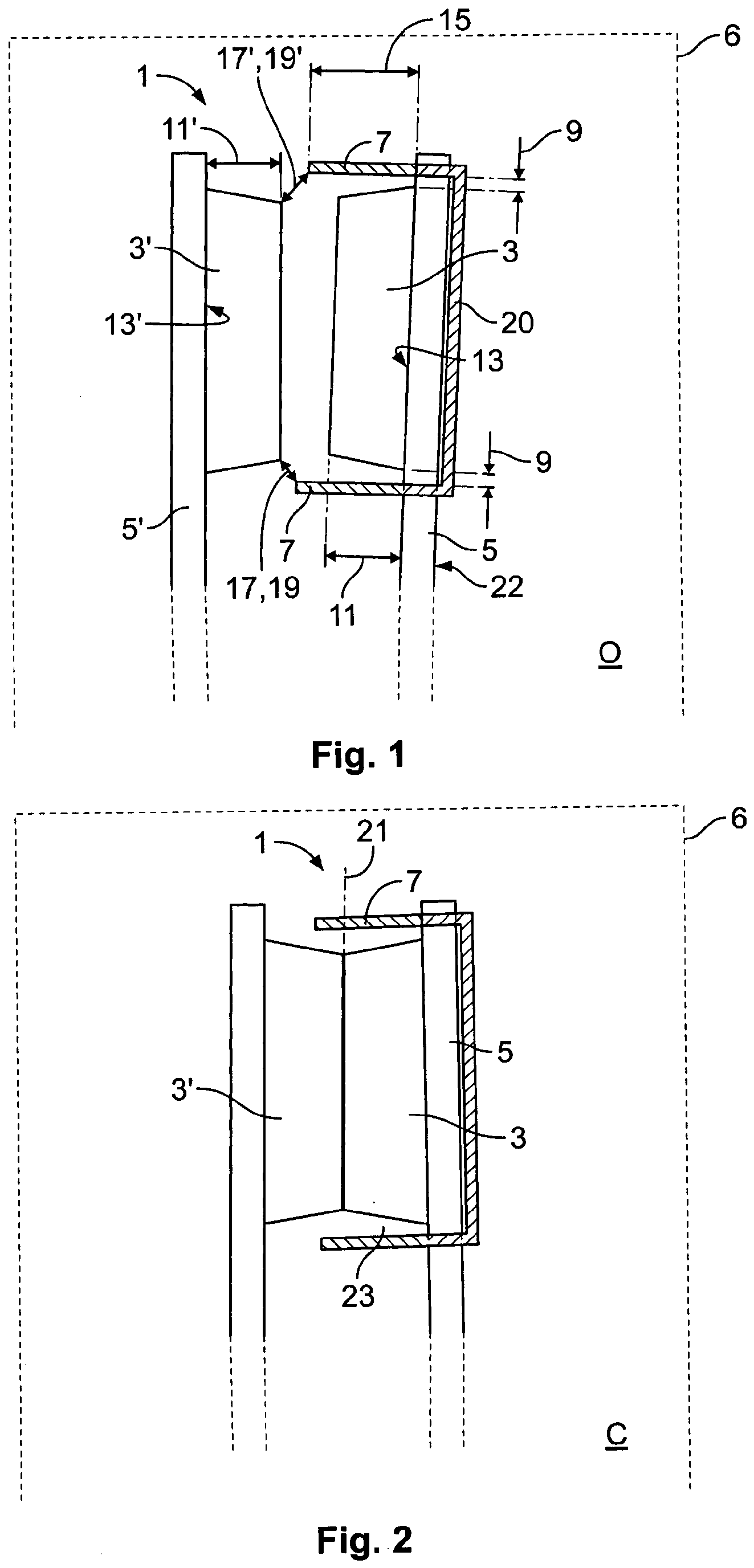
Fig. 1 is a schematic cross-sectional view of an exemplary embodiment of an arrangement
for an electric switching device in an open position;
Fig. 2 shows a schematic cross-sectional view of the same embodiment as shown in Fig.
1 in a closed position;
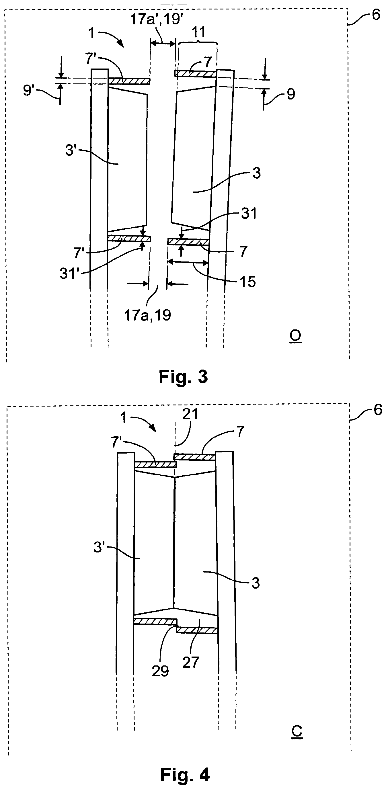
Fig. 3 shows a schematic cross-sectional view of another embodiment of the arrangement
for an electric switching device in an open position;
Fig. 4 shows a schematic cross-sectional view of the same embodiment as shown in Fig.
3 in a closed position.
[0025] Fig. 1 shows an arrangement 1 for an electric switching device. The arrangement 1
comprises two opposing contacts 3, 3'. The contacts 3, 3' are located on terminals
5, 5'. The arrangement 1 may be situated in a surrounding switching chamber 6. In
the open position O, the contacts 3, 3' are spaced apart from each other. The contacts
3', 3' may have the shape of a disc. In the cross-sectional view, the contacts 3,
3' may taper towards the opposing contacts 3', 3. The contacts 3, 3' are made by contact
material at least in part. The contact 3 is surrounded by a barrier wall 7. The barrier
wall 7 may be shaped as a ringwall. The barrier wall 7 may be made from an insulating
material. The barrier wall 7 protrudes into the direction of the opposing contact
3'.
[0026] The distance 9 between the barrier wall 7 and the contact 3 is smaller than the height
11 of the contact 3. The contacts 3, 3' project from bases 13, 13' to the contact
heights 11, 11'. The contact heights 11 and 11' are not necessarily identical. The
barrier wall 7 extends to the wall height 15. The wall height 15 is greater than the
height 11 of the contact 3.
[0027] Insulating gaps 17, 17' extend between the barrier wall 7 and the opposing contact
3'. The insulating gap lengths 19 and 19' are adapted to prevent electric sparkovers
between the barrier wall 7 and the opposing contact 3'. The insulating gaps 17, 17'
are necessary to avoid sparkovers in the case that the barrier wall 7 has conducting
properties, for example from deposited contact material.
[0028] The barrier wall 7 may comprise a holding structure 20 which extends at least partially
around a backside 22 of the terminal 5.
[0029] Fig. 2 shows the arrangement 1 as shown in Fig. 1 in the closed position C. In the
closed position C, the contacts 3, 3' contact each other. The barrier wall 7, which
projects into the direction of the opposing contact 3', surrounds the opposing contact
3' partially in the closed position C. The barrier wall 7 extends from the terminal
5 further than a contact plane 21 of the contacts 3, 3' in the closed position C.
[0030] The barrier wall 7 forms an open chamber 23 around the contacts 3, 3'. The open chamber
23 reduces the expansion of evaporated contact material. However, the open chamber
23 cannot totally prevent the expansion of evaporated contact material into the switching
chamber 6. If contact material is deposited on elements outside of the open chamber
23, the barrier wall 7 may interrupt conductive way paths or, if the barrier wall
7 itself is covered with contact material, it may extend the conductive way paths
to an extent which still allows the full function of the switching device.
[0031] Fig. 3 shows another embodiment of an arrangement 1 according to the invention in
an open position O. For the sake of clarity, only differences to the previously described
embodiment will be described hereinafter. Both contacts 3, 3' are surrounded by barrier
walls 7, 7'. The barrier walls 7, 7' project towards each other. In the open position
O, insulating gaps 17a, 17'a extend not only between a barrier wall 7, 7' and its
corresponding opposing contact 3, 3', respectively, but also between the barrier walls
7 and 7'. The lengths 19, 19' are adapted to prevent electric sparkovers between the
barrier walls 7, 7' in the case that the barrier walls 7, 7' have conducting properties.
The distance 9 between the barrier wall 7 and the contact 3 is greater than the distance
9' between the opposing barrier wall 7' and the contact 3'.
[0032] Fig. 4 shows the embodiment as described with respect to Fig. 3 in the closed position
C. In the closed position C, both barrier walls 7, 7' extend beyond the contact plane
21. In the closed position C, the barrier walls 7 and 7' overlap. The overlapping
barrier walls 7, 7' form a chamber 27 which surrounds the contacts 3, 3'. The chamber
27 effectively reduces or even prevents the expansion of evaporated contact material
into the switching chamber 6. Therefore, the risk of the formation of conductive way
paths between the contacts 3, 3' is reduced or prevented.
[0033] Between the barrier walls 7, 7' a moving space 29 may be formed, which is adapted
to prevent sticking of the barrier walls in the closed position C. The moving space
29 may be dimensioned in a way that it allows the movement of the barrier walls 7,
7' - but at the same time, prevents the expansion of evaporated contact material into
the switching chamber 6 at least to a noncritical extent.
[0034] In an alternative embodiment, the barrier walls 7, 7' may abut on each other. In
that case, both barrier walls 7, 7' extend preferably to the contact plane 21 and
accordingly the contact height 11 equals the height 15 of the barrier walls 7, 7'.
[0035] In a second alternative embodiment, one of the barrier walls 7, 7' may have a greater
wall thickness 31, 31' than the opposing barrier wall 7, 7' and a ring-like opening
in the barrier wall 7, 7'. The ring-like opening may extend into the direction of
the opposing barrier wall 7, 7' and the opposing barrier wall 7, 7' may protrude into
the ring-like opening in the closed position C.
Reference Signs List
| No. |
Part |
| 1 |
Arrangement |
| 3, 3' |
Contacts |
| 5 |
Terminal |
| 6 |
Switching chamber |
| 7, 7' |
Barrier wall |
| 9, 9' |
Distance |
| 11 |
Height of contact |
| 13, 13' |
Bases |
| 15 |
Wall height |
| 17, 17', 17a, 17'a |
Insulating gap |
| 19, 19' |
Insulating gap lengths |
| 20 |
Holding structure |
| 21 |
Contact plane |
| 22 |
Backside |
| 23 |
Open chamber |
| 27 |
Chamber |
| 29 |
Moving space |
| 31, 31' |
Wall thickness |
| O |
Open position |
| C |
Closed position |
| |
|
| |
|
| |
|
| |
|
| |
|
| |
|
| |
|
| |
|
| |
|
| |
|
| |
|
| |
|
| |
|
| |
|
1. Arrangement (1) for limiting or preventing the formation of creeping currents between
opened contacts (3, 3') of an electric switching device such as a relay or a contactor,
wherein the arrangement comprises two opposing contacts (3, 3') for performing the
switching operation and wherein at least one of the contacts (3, 3') is surrounded
laterally at least in parts by a barrier wall (7, 7'), characterised in that the barrier wall (7, 7') is made from an insulating material.
2. Arrangement (1) for an electric switching device according to claim 1, characterised in that a distance (9, 9') between the at least one contact (3, 3') and its surrounding barrier
wall (7, 7') is always smaller than a height (11) to which the at least one contact
(3, 3') projects from a base (13, 13').
3. Arrangement (1) for an electric switching device according to claim 1 or 2, characterised in that the at least one barrier wall (7, 7') projects into the direction of the opposing
contact (3', 3).
4. Arrangement (1) for an electric switching device according to one of the claims 1
to 3, characterised in that at least one of the contacts (3, 3') and its surrounding barrier wall (7, 7') are
both located on a terminal (5, 5').
5. Arrangement (1) for an electric switching device according to one of the claims 1
to 4, characterised in that the at least one contact (3, 3') projects from a base (13, 13') to a contact height
(11), the barrier wall (7, 7') projecting from the base (13, 13') at least to the
contact height (11).
6. Arrangement (1) for an electric switching device according to one of the claims 1
to 5, characterised in that the at least one barrier wall (7, 7') is shaped as a ring wall.
7. Arrangement (1) for an electric switching device according to one of the claims 1
to 6, characterised in that, at least in a closed position (C), the at least one barrier wall (7, 7') forms a
chamber (23, 27), which separates the two contacts (3, 3') from a surrounding switching
chamber (6).
8. Arrangement (1) for an electric switching device according to one of the claims 1
to 7, characterised in that the contacts (3, 3') each comprise at least one barrier wall (7, 7'), the barrier
walls (7, 7') opposing each other.
9. Arrangement (1) for an electric switching device according to claim 8, characterised in that, in the closed position (C), one of the barrier walls (7, 7') protrudes into an opening
of the opposing barrier wall (7', 7).
10. Arrangement (1) for an electric switching device according to claim 8 or 9, characterised in that, in the closed position (C), the opposing barrier walls (7, 7') overlap.
11. Arrangement (1) for an electric switching device according to one of the claims 1
to 10, characterised in that at least one barrier wall (7, 7') is made from a plastic material.
12. Arrangement (1) for an electric switching device according to one of the claims 1
to 11, characterised in that at least one barrier wall (7, 7') comprises a holding structure (20), the holding
structure extending at least in parts around a backside (22) of the terminal (5) opposite
to the contacts (3, 3').
13. Arrangement (1) for an electric switching device according to one of the claims 1
to 12, characterised in that an insulating gap (17, 17') extends between one contact (3, 3') and the barrier wall
(7', 7) of the opposing contact (3', 3), at least in an open position (O).
14. Arrangement (1) for an electric switching device according to one of the claims 8
to 13, characterised in that an insulating gap (17a, 17'a) extends between the barrier wall (7, 7') of one contact
(3, 3') and the opposing barrier wall (7', 7) of the opposing contact (3', 3), at
least in the open position (O).
15. Electric switching device comprising an arrangement (1) according to one of the claims
1 to 14, characterised in that the electric switching device comprises a switching chamber (6), in which opposing
contacts (3, 3') are located on terminals (5, 5'), the opposing contacts (3, 3') being
each surrounded by a barrier wall (7, 7'), the barrier walls (7, 7') being shaped
as ring walls, the barrier walls (7, 7') of opposing contacts (3, 3') forming a chamber
(27), which separates the contacts (3, 3') from the surrounding switching chamber
at least in the closed position (C).
1. Anordnung (1), mit der die Ausbildung von Kriechströmen zwischen geöffneten Kontakten
(3, 3') einer elektrischen Schalteinrichtung, wie beispielsweise eines Relais oder
eines Schütz, eingeschränkt oder verhindert wird, wobei die Anordnung zwei einander
gegenüberliegende Kontakte (3, 3') zum Durchführen des Schaltvorgangs umfasst und
wenigstens einer der Kontakte (3, 3') seitlich wenigstens teilweise von einer Sperrwand
(7, 7') umgeben ist, dadurch gekennzeichnet, dass die Sperrwand (7, 7') aus einem isolierenden Material besteht.
2. Anordnung (1) für eine elektrische Schalteinrichtung nach Anspruch 1, dadurch gekennzeichnet, dass ein Zwischenraum (9, 9') zwischen dem wenigstens einen Kontakt (3, 3') und seiner
umgebenden Sperrwand (7, 7') stets kleiner ist als eine Höhe (11), um die der wenigstens
eine Kontakt (3, 3') von einer Basis (13, 13') vorsteht.
3. Anordnung (1) für eine elektrische Schalteinrichtung nach Anspruch 1 oder 2, dadurch gekennzeichnet, dass die wenigstens eine Sperrwand (7, 7') in der Richtung des gegenüberliegenden Kontaktes
(3', 3) vorsteht.
4. Anordnung (1) für eine elektrische Schalteinrichtung nach einem der Ansprüche 1 bis
3, dadurch gekennzeichnet, dass sich sowohl wenigstens einer der Kontakte (3, 3') als auch seine umgebende Sperrwand
(7, 7') an einem Anschluss (5, 5') befinden.
5. Anordnung (1) für eine elektrische Schalteinrichtung nach einem der Ansprüche 1 bis
4, dadurch gekennzeichnet, dass der wenigstens eine Kontakt (3, 3') von einer Basis (13, 13') bis zu einer Kontakt-Höhe
(11) vorsteht, wobei die Sperrwand (7, 7') von der Basis (13, 13') wenigstens bis
zu der Kontakt-Höhe (11) vorsteht.
6. Anordnung (1) für eine elektrische Schalteinrichtung nach einem der Ansprüche 1 bis
5, dadurch gekennzeichnet, dass die wenigstens eine Sperrwand (7, 7') die Form einer Ringwand hat.
7. Anordnung (1) für eine elektrische Schalteinrichtung nach einem der Ansprüche 1 bis
6, dadurch gekennzeichnet, dass wenigstens in einer geschlossenen Position (C) die wenigstens eine Sperrwand (7,
7') eine Kammer (23, 27) bildet, die die zwei Kontakte (3, 3') von einer umgebenden
Schalt-Kammer (6) trennt.
8. Anordnung (1) für eine elektrische Schalteinrichtung nach einem der Ansprüche 1 bis
7, dadurch gekennzeichnet, dass die Kontakte (3, 3') jeweils wenigstens eine Sperrwand (7, 7') umfassen, wobei die
Sperrwände (7, 7') einander gegenüberliegen.
9. Anordnung (1) für eine elektrische Schalteinrichtung nach Anspruch 8, dadurch gekennzeichnet, dass in der geschlossenen Position (C) eine der Sperrwände (7, 7') in eine Öffnung der
gegenüberliegenden Sperrwand (7', 7) hinein vorsteht.
10. Anordnung (1) für eine elektrische Schalteinrichtung nach Anspruch 8 oder 9, dadurch gekennzeichnet, dass sich in der geschlossenen Position (C) die einander gegenüberliegenden Sperrwände
(7, 7')überlappen.
11. Anordnung (1) für eine elektrische Schalteinrichtung nach einem der Ansprüche 1 bis
10, dadurch gekennzeichnet, dass wenigstens eine Sperrwand (7, 7') aus einem Kunststoffmaterial besteht.
12. Anordnung (1) für eine elektrische Schalteinrichtung nach einem der Ansprüche 1 bis
11, dadurch gekennzeichnet, dass wenigstens eine Sperrwand (7, 7') eine Halte-Struktur (20) umfasst, wobei sich die
Halte-Struktur wenigstens teilweise um eine Rückseite (22) des Anschlusses (5) herum
erstreckt, die den Kontakten (3, 3') gegenüberliegt.
13. Anordnung (1) für eine elektrische Schalteinrichtung nach einem der Ansprüche 1 bis
12, dadurch gekennzeichnet, dass sich, wenigstens in einer offenen Position (O), ein isolierender Spalt (17, 17')
zwischen einem Kontakt (3, 3') und der Sperrwand (7', 7) des gegenüberliegenden Kontaktes
(3', 3) erstreckt.
14. Anordnung (1) für eine elektrische Schalteinrichtung nach einem der Ansprüche 8 bis
13, dadurch gekennzeichnet, dass sich, wenigstens in der offenen Position, ein isolierender Spalt (17a, 17'a) zwischen
der Sperrwand (7, 7') eines Kontaktes (3, 3') und der gegenüberliegenden Sperrwand
(7', 7) des gegenüberliegenden Kontaktes (3', 3) erstreckt.
15. Elektrische Schalteinrichtung, die eine Anordnung (1) nach einem der Ansprüche 1 bis
14 umfasst, dadurch gekennzeichnet, dass die elektrische Schalteinrichtung eine Schalt-Kammer (6) umfasst, in der einander
gegenüberliegende Kontakte (3, 3') an Anschlüssen (5, 5') angeordnet sind, wobei die
einander gegenüberliegenden Kontakte (3, 3') jeweils von einer Sperrwand (7, 7') umgeben
sind, die Sperrwände (7, 7') die Form von Ringwänden haben und die Sperrwände (7,
7') einander gegenüberliegender Kontakte (3, 3') eine Kammer (27) bilden, die die
Kontakte (3, 3') wenigstens in der geschlossenen Position (C) von der umgebenden Schalt-Kammer
trennt.
1. Agencement (1) pour limiter ou empêcher la formation de courants de fuite entre des
contacts ouverts (3, 3') d'un dispositif de commutation électrique tel qu'un relais
ou un contacteur l'agencement comprenant deux contacts opposés (3, 3') pour exécuter
l'opération de commutation et dans lequel au moins l'un des contacts (3, 3') est entouré
latéralement au moins en partie par une paroi faisant écran (7, 7'), caractérisé en ce que la paroi faisant écran (7, 7') est réalisée dans un matériau isolant.
2. Agencement (1) de dispositif de commutation électrique selon la revendication 1, caractérisé en ce qu'une distance (9, 9') entre l'au moins un contact (3, 3') et sa paroi faisant écran
(7, 7') entourante est toujours inférieure à une hauteur (11) par laquelle l'au moins
un contact (3, 3') fait saillie depuis une base (13, 13').
3. Agencement (1) de dispositif de commutation électrique selon la revendication 1 ou
2, caractérisé en ce que l'au moins une paroi faisant écran (7, 7') fait saillie dans la direction du contact
opposé (3', 3).
4. Agencement (1) de dispositif de commutation électrique selon l'une des revendications
1 à 3, caractérisé en ce qu'au moins l'un des contacts (3, 3') et sa paroi faisant écran (7, 7') entourante sont
tous les deux situés sur une borne (5, 5').
5. Agencement (1) de dispositif de commutation électrique selon l'une des revendications
1 à 4, caractérisé en ce que l'au moins un contact (3, 3') fait saillie depuis une base (13, 13') jusqu'à une
hauteur de contact (11), la paroi faisant écran (7, 7') faisant saillie depuis la
base (13, 13') au moins jusqu'à la hauteur de contact (11).
6. Agencement (1) de dispositif de commutation électrique selon l'une des revendications
1 à 5, caractérisé en ce que l'au moins une paroi faisant écran (7, 7') a la forme d'une paroi annulaire.
7. Agencement (1) de dispositif de commutation électrique selon l'une des revendications
1 à 6, caractérisé en ce que, au moins dans une position fermée (C), l'au moins une paroi faisant écran (7, 7')
forme une chambre (23, 27), laquelle sépare les deux contacts (3, 3') d'une chambre
de commutation périphérique (6).
8. Agencement (1) de dispositif de commutation électrique selon l'une des revendications
1 à 7, caractérisé en ce que les contacts (3, 3') comprennent chacun au moins une paroi faisant écran (7, 7'),
les parois faisant écran (7, 7') se faisant face.
9. Agencement (1) de dispositif de commutation électrique selon la revendication 8, caractérisé en ce que, dans la position fermée (C), l'une des parois faisant écran (7, 7') fait saille
dans une ouverture de la paroi faisant écran (7', 7) opposée.
10. Agencement (1) de dispositif de commutation électrique selon la revendication 8 or
9, caractérisé en ce que, dans la position fermée (C), les parois faisant écran (7, 7') se chevauchent.
11. Agencement (1) de dispositif de commutation électrique selon l'une des revendications
1 à 10, caractérisé en ce qu'au moins une paroi faisant écran (7, 7') est réalisée en un matériau plastique.
12. Agencement (1) de dispositif de commutation électrique selon l'une des revendications
1 à 11, caractérisé en ce qu'au moins une paroi faisant écran (7, 7') comprend une structure de support (20), la
structure de support s'étendant au moins en partie autour d'une partie arrière (22)
de la borne (5) opposée aux contacts (3, 3').
13. Agencement (1) de dispositif de commutation électrique selon l'une des revendications
1 à 12, caractérisé en ce qu'un espace isolant (17, 17') s'étend entre un contact (3, 3') et la paroi faisant écran
(7', 7) du contact opposé (3', 3), au moins dans une position ouverte (0).
14. Agencement (1) de dispositif de commutation selon l'une des revendications 8 à 13,
caractérisé en ce qu'un espace isolant (17a, 17'a) s'étend entre la paroi faisant écran (7, 7') d'un contact
(3, 3') et la paroi faisant écran (7', 7) opposée du contact (3', 3) opposé, au moins
dans la position ouverte (0).
15. Dispositif de commutation électrique comprenant un agencement (1) selon l'une des
revendications 1 à 14, caractérisé en ce que le dispositif de commutation électrique comprend une chambre de commutation (6),
dans laquelle des contacts opposés (3, 3') sont situés sur des bornes (5, 5'), les
contacts opposés (3, 3') étant entourés chacun par une paroi faisant écran (7, 7'),
les parois faisant écran (7, 7') ayant la forme de parois annulaires, les parois faisant
écran (7, 7') de contacts opposés (3, 3') formant une chambre (27), laquelle sépare
les contacts (3, 3') de la chambre de commutation périphérique au moins dans la position
fermée (C).
REFERENCES CITED IN THE DESCRIPTION
This list of references cited by the applicant is for the reader's convenience only.
It does not form part of the European patent document. Even though great care has
been taken in compiling the references, errors or omissions cannot be excluded and
the EPO disclaims all liability in this regard.
Patent documents cited in the description