| (19) |
 |
|
(11) |
EP 3 347 574 B1 |
| (12) |
EUROPEAN PATENT SPECIFICATION |
| (45) |
Mention of the grant of the patent: |
|
10.07.2019 Bulletin 2019/28 |
| (22) |
Date of filing: 18.08.2016 |
|
| (51) |
International Patent Classification (IPC):
|
| (86) |
International application number: |
|
PCT/BE2016/000038 |
| (87) |
International publication number: |
|
WO 2017/041146 (16.03.2017 Gazette 2017/11) |
|
| (54) |
ORC FOR TRANSFORMING WASTE HEAT FROM A HEAT SOURCE INTO MECHANICAL ENERGY AND COMPRESSOR
INSTALLATION MAKING USE OF SUCH AN ORC
ORGANISCHER RANKINE-ZYKLUS ZUR UMWANDLUNG VON ABWÄRME AUS EINER WÄRMEQUELLE IN MECHANISCHE
ENERGIE UND KOMPRESSORANLAGE MIT VERWENDUNG SOLCH EINES ORGANISCHEN RANKINE-ZYKLUS
CYCLE DE RANKINE À CALOPORTEUR ORGANIQUE (ORC) PERMETTANT DE TRANSFORMER UNE CHALEUR
RÉSIDUELLE PROVENANT D'UNE SOURCE DE CHALEUR EN ÉNERGIE MÉCANIQUE ET INSTALLATION
DE COMPRESSEUR UTILISANT UN TEL ORC
|
| (84) |
Designated Contracting States: |
|
AL AT BE BG CH CY CZ DE DK EE ES FI FR GB GR HR HU IE IS IT LI LT LU LV MC MK MT NL
NO PL PT RO RS SE SI SK SM TR |
| (30) |
Priority: |
08.09.2015 US 201562215247 P
17.08.2016 BE 201605643
|
| (43) |
Date of publication of application: |
|
18.07.2018 Bulletin 2018/29 |
| (73) |
Proprietor: Atlas Copco Airpower, Naamloze Vennootschap |
|
2610 Wilrijk (BE) |
|
| (72) |
Inventor: |
|
- ÖHMAN, Henrik
2610 Wilrijk (BE)
|
| (74) |
Representative: Van Minnebruggen, Ewan Benito Agnes et al |
|
Atlas Copco Airpower, N.V.
Airtec Division
P.O. Box 101
Boomsesteenweg 957
2610 Wilrijk
2610 Wilrijk (BE) |
| (56) |
References cited: :
FR-A1- 2 401 380
US-A1- 2010 034 684
US-A1- 2012 312 009
|
JP-A- 2013 167 241
US-A1- 2012 286 524
|
|
| |
|
|
|
|
| |
|
| Note: Within nine months from the publication of the mention of the grant of the European
patent, any person may give notice to the European Patent Office of opposition to
the European patent
granted. Notice of opposition shall be filed in a written reasoned statement. It shall
not be deemed to
have been filed until the opposition fee has been paid. (Art. 99(1) European Patent
Convention).
|
[0001] The present invention relates to an ORC for transforming waste heat from a heat source
into mechanical energy and compressor installation making use of such an ORC for transforming
its waste compression heat into mechanical energy.
[0002] Power cycles for WTP (Waste heat To Power) are well described, such as ORC, Kalina,
Trilateral Flash etc.
[0003] Such power cycles are designed to recover waste heat produced for example by a compressor
and to transform said energy into useful mechanical energy that can be used for instance
for driving a generator for generating electrical power.
[0004] The use of an ORC (Organic Rankine Cycle) is in particular known to recover waste
energy of heat sources with relatively high temperature like the heat of compressed
gas produced by a compressor installation.
[0005] Such known ORC's comprise a closed loop circuit containing a two-phase working fluid,
the circuit further comprising a liquid pump for circulating the fluid in the circuit
consecutively through an evaporator which is in thermal contact with the heat source
to evaporate the working fluid; through an expander like a turbine for transforming
the thermal energy transmitted to the gaseous working fluid produced in the evaporator
into useful mechanical energy; and finally through a condenser which is in thermal
contact with a cooling medium like water or ambient air in order to transform the
gaseous working fluid into liquid that can be returned to the evaporator for the next
working cycle of the working fluid.
[0006] In compressor installations the ORC is used for cooling the hot gasses produced by
compression by bringing these hot gasses in contact with the evaporator of the ORC
and at the same time to use the ORC for transforming the heat recovered in the evaporator
into useful energy in the expander.
[0007] The waste heat in compressor installations is available at relatively high temperatures,
typically at 150°C or higher. At the same time, the cooling needs to reduce the hot
compressed gasses to very low levels, typically less than 10°C above the temperature
of the working fluid at the entry of the evaporator.
[0008] The known power cycles for WTP, designed to operate between the temperature levels
of the working fluid such as cooling water and the compressed gas, are faced with
a performance dilemma in that they require choosing between two alternatives.
[0009] Either the power cycle uses all the available waste heat present in the compressed
gas, but suffers from a very low cycle efficiency or the power cycle uses only a part
of the heat and will only partially cool the compressed gas but at a relatively high
efficiency. In the last case, a separate air cooler is required after the power cycle
evaporator in order to reach the correct cooling of the compressed gas.
[0010] The known power cycles have been adopted to be suitable for heat sources such as
compressed gas, which have the difficulty that the temperature of the compressed gas
varies, meaning that the waste heat available varies over time.
[0011] A first approach is to cool the compressed gas with a cooling agent, often water,
then cooling the cooling agent with a power cycle, which in turn in cooled by cooling
water of ambient air. This solution introduces very large thermodynamic losses, due
to the heat exchange across large temperature differences, and leads to very low system
efficiency.
[0012] A second approach is working with varying temperature evaporation, such as Kalina
cycles and supercritical ORC. Also an ORC operating with zeotropic fluid mixes as
a working fluid is a known approach to reduce the thermodynamic losses due to varying
temperature evaporation. This approach leads to technically complex and therefore
expensive systems.
[0013] It is an objective of the present invention to give a solution to one or more of
the above-mentioned and other disadvantages.
[0014] Therefore the invention aims an ORC for transforming waste heat from a heat source
containing compressed gas into mechanical energy, the ORC comprising a closed circuit
containing a two-phase working fluid, the circuit comprising a liquid pump for circulating
the working fluid in the circuit consecutively through an evaporator which is in thermal
contact with the heat source; through an expander like a turbine for transforming
the thermal energy of the working fluid into mechanical energy; and through a condenser
which is in thermal contact with a cooling element, whereby the ORC is equipped with
means for determining the mechanical energy generated by the expander and a control
device adapted to regulate the vapour fraction of the working fluid entering the expander,
whereby the control device is adapted to regulate the afore-mentioned vapour fraction
based on the determined mechanical energy such that the mechanical energy generated
by the expander is maximum and whereby the expander is of any kind suitable to accept
a mixture of liquid and gaseous working fluid.
[0015] By regulating the vapour fraction, the ratio of liquid to gaseous or vaporous working
fluid entering the expander will be adjusted.
[0016] The mechanical energy generated by the expander can be considered as the ORC output
power.
[0017] An advantage of such an ORC according to the invention is that it uses a variable
vapour fraction at the entry of the expander to adapt to the compressed gas temperature
variations, such that a higher efficiency can be obtained compared to conventional
ORC and Trilateral Flash cycles.
[0018] Another advantage is that an ORC according to the invention is less complex and less
costly than variable evaporation temperature systems such as Kalina cycles, supercritical
ORC's and ORC's with zeotropic fluid blends.
[0019] It is important to note that in the evaporator, which is in thermal contact with
the compressed gas, the working fluid will be heated to its boiling temperature and
thereafter to at least partially evaporate the working fluid.
[0020] In other words: the ratio of heat used for preheating to the heat used for evaporation
is increased by only evaporating part of the working fluid.
[0021] This mixture of liquid working fluid and evaporated or vapourous or gaseous working
fluid will enter the expander.
[0022] By lowering for example the pump capacity, the amount of liquid working fluid that
is evaporated in the evaporator can be increased, i.e. more heat is used for the evaporation.
[0023] This will reduce the average temperature difference in the evaporator between the
working fluid absorbing heat and the compressed gas emitting the heat, yet at the
same time the physical evaporation temperature of the fluid is constant.
[0024] This will overcome the performance dilemma related to the temperature difference
between the working fluid and the compressed gas that the known power cycles for WTP
are confronted with, as explained above.
[0025] According to a preferred embodiment the control device will regulate the vapour fraction
of the working fluid entering the expander, by varying the working fluid flow through
the pump and/or by varying the working fluid flow through the expander.
[0026] Varying the working fluid flow through the pump or expander means that the pump or
expander capacity is varied.
[0027] The control device will regulate the pump and/or expander capacity and as a consequence
the vapour fraction of the working fluid entering the expander in function of the
mechanical energy generated by the expander. In particular, the control device will
regulate the pump and/or expander capacity such that this mechanical energy is maximum.
[0028] It is clear however, that many other regulations can be conceived for varying the
vapour fraction of the working fluid entering the expander. Any regulation which can
vary the vapour fraction of the working fluid entering the expander can be used for
the pending invention.
[0029] Preferably, the control device will regulate the vapour fraction of the working fluid
entering the expander in a continuous manner.
[0030] Such a regulation will allow that the vapour fraction of the working fluid entering
the expander is variable.
[0031] This means that the control device will respond to changing operating conditions
such that an optimal efficiency, i.e. a maximum WTP power output, can be achieved
at all operating conditions.
[0032] The present invention also relates to a compressor installation comprising a compressor
element for compressing a gas and a cooler for cooling the compressed gas, whereby
the compressor installation also comprises an ORC circuit according to the invention
and whereby the above-mentioned cooler is integrated in an heat exchanger which also
integrates the evaporator of the ORC for heat transfer between the cooler and the
evaporator.
[0033] With the intention of better showing the characteristics of the invention, hereafter,
as an example without any limitative character, some preferred embodiments are described
of an ORC according to the invention for transforming waste heat from a heat source
into mechanical energy and of a compressor installation making use of such an ORC,
with reference to the accompanying drawings, wherein:
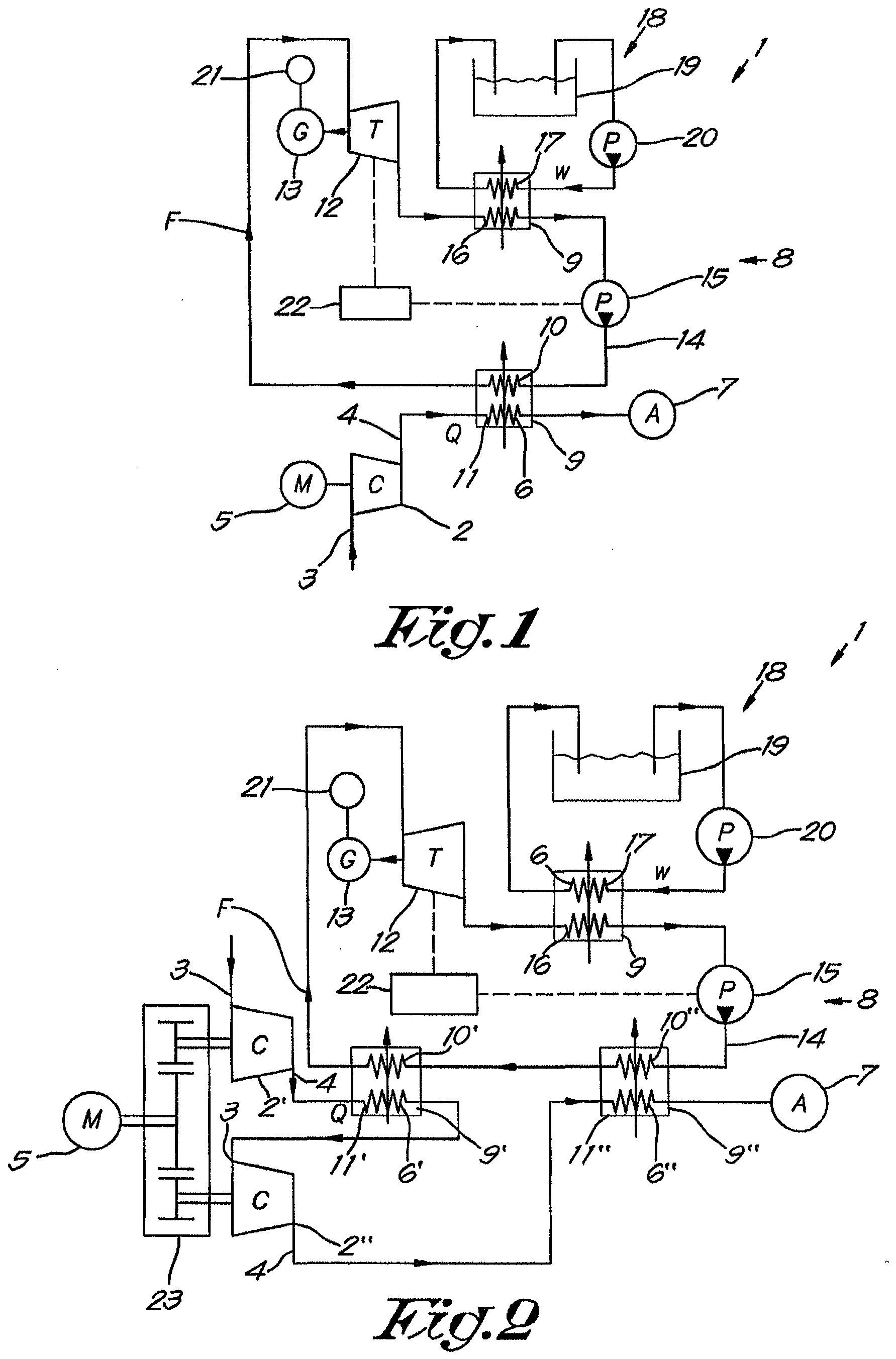
figure 1 schematically represents a single stage compressor installation making use
of an ORC system according to the invention;
figure 2 schematically represents a multi stage compressor installation according
to the invention;
figures 3 to 4 represent different embodiments of the multi stage compressor installation
according of figure 2.
[0034] The compressor installation 1 represented in figure 1 comprises a compressor element
2 with an inlet 3 and an outlet 4 and driven by a motor 5 for compressing a gas flow
Q and a cooler 6 for cooling the compressed gas before it is supplied to a net 7 of
consumers of compressed gas.
[0035] The afore-mentioned gas can be for example air or nitrogen. However, the invention
is not limited thereto.
[0036] The compressor installation 1 further comprises an ORC 8 according to the invention
wherein the above-mentioned cooler 6 is integrated in an heat exchanger 9 which also
integrates the evaporator 10 of the ORC 8 for recovering the waste heat of the compressed
gas used as a heat source 11 and transforming said heat into useful mechanical energy
by means of an expander 12 of the ORC 8, for example a turbine driving an electrical
generator 13 as shown in the example of figure 1.
[0037] The ORC 8 comprises a closed circuit 14 containing a two-phase organic working fluid
with a boiling temperature below the temperature of the heat source 11, i.e. the compressed
gas, the working fluid being continuously circulated around in the circuit 14 by means
of a liquid pump 15 in the direction as indicated with arrows F.
[0038] The working fluid is made to flow consecutively through the evaporator 10 which is
in thermal contact with the heat source 11; then through the expander 12 and finally
through a condenser 16 before being launched again by the pump 15 for a next cycle
in the circuit 14.
[0039] The condenser 16 is, in this example, in thermal contact with a cooling element 17
of a cooling circuit 18 which, in the example of figure 1, is represented as a supply
of cold water W taken from a tank 19 to circulate through the condenser 16 by means
of a pump 20.
[0040] According to the invention, the ORC 8 is equipped with means 21 for determining the
mechanical energy generated by the expander 12.
[0041] These means 21 can be for example a Power meter or Power sensor.
[0042] The ORC 8 is further equipped with a control device 22 that can regulate the vapour
fraction of the working fluid entering the expander 12.
[0043] Normal operation of the ORC 8 according to the invention is that the control device
22 will regulate the afore-mentioned vapour fraction based on the determined mechanical
energy by the means 21 such that the mechanical energy is maximum.
[0044] In the example of figure 1 and according to a preferred characteristic of the invention,
the control device 22 will regulate the vapour fraction of the working fluid entering
the expander 12, by varying the working fluid flow through the pump 15 and by varying
the working fluid flow through the expander 12.
[0045] It is of course also possible that the control device 22 will only regulate the expander
12 or the pump 15.
[0046] In this case however, the control device 22 will regulate the vapour fraction of
the working fluid entering the expander 12 by switching repeatedly between two control
algorithms.
[0047] A first control algorithm consists of varying the working fluid flow through the
pump 15 until the mechanical energy generated by the expander 12 is at a local maximum.
[0048] The second control algorithm consists of varying the working fluid flow through the
expander 12 until the mechanical energy generated by the expander 12 is at a further
optimize maximum.
[0049] The control device 22 will vary the working fluid flow through the expander 12 or
the pump 15, i.e. vary the expander 12 or pump 15 capacity, and at the same time determine
the mechanical energy generated by the expander 12, i.e. determine the ORC power output,
and will select the expander 12 or pump 15 capacity for which the determined the ORC
power output is at a maximum.
[0050] After the first control algorithm, the ORC power output will be optimized in function
of only the pump 15 capacity. This means that the ORC power output will be at a local
maximum.
[0051] By applying the second control algorithm, the ORC power output will be optimized
in function of the expander 12 capacity, such that an optimized maximum can be reached.
[0052] By switching again to the first control algorithm, the ORC power output will be optimized
again in function of the pump 15, such that changes in operating conditions can and
will be taken into account.
[0053] Such changes in operation conditions are: changes in the temperature of the compressed
air to be cooled, changes in the flow of the compressed air, changes in ambient temperatures,
changes in cooling water flow, changes in cooling water temperature or changes in
heat exchanger efficiency.
[0054] By applying such a regulation, the control device 22 will regulate the vapour fraction
of the working fluid entering the expander 12 in a continuous manner, such that changes
in operating conditions can be readily acted upon.
[0055] In this way, a maximum ORC power output can be guaranteed under all operating conditions.
[0056] In order to vary the working fluid flow through the expander 12, several options
are possible.
[0057] The expander 12 capacity can be varied by means of varying the speed of the expander
12, as in the present example or by means of a by-pass over the expander 12, by means
or slide valves and/or lift valves, by varying swept volume of the expander 12 or
by means of varying the oil injection of the expander 12.
[0058] Also to vary the working fluid flow through the pump 15, several options are possible.
[0059] The pump 15 capacity can be varied by means of varying the speed of the pump 15,
as in the present example or by means of a by-pass over the pump 15, by means of varying
swept volume of the pump 15 or by means of varying the on-off frequency of the pump
15.
[0060] According to a preferred embodiment of the invention, the vapour fraction of the
working fluid entering the expander 12 is between 10% and 99% mass fraction. It is
of course also possible that the vapour fraction of the working fluid entering the
expander 12 is kept between different limits, for example between 20% and 95% mass
fraction or between 40% and 90% mass fraction.
[0061] The expander 12 can be any kind of expander 12 capable of generating mechanical energy
by expansion of a two phase fluid supply, i.e. a mixture of liquid and gaseous working
fluid. Preferably, a volumetric expander 12 like a screw expander 12 or a mechanical
cylinder or the like which can accept a mixture of liquid and gaseous working fluid.
[0062] The compressor element 2 can also be of any kind, in particular an oil free air compressor
element 2.
[0063] It is also clear that the cooling of the condenser 16 can be realized in other ways
than in the example of figure 1, for example by blowing ambient air over the condenser
16 by means of a fan or the like.
[0064] Preferably a working fluid is used of which the boiling temperature is lower than
90°C or even lower than 60°C, depending on the temperature of the available heat source
11, i.e. the temperature of the compressed gas to be cooled.
[0065] An example of a suitable organic working fluid is 1,1,1,3,3-pentafluoropropaan. The
working fluid could be mixed with a suitable lubricant for the lubrication of at least
part of the moving parts of the ORC 8. Alternatively, the working fluid itself could
act as a lubricant, meaning that a working fluid is chosen which has lubricating properties.
[0066] In figure 2 a multistage compressor installation 1 according to the invention is
represented with in this case two compressor elements, a first stage compressor element
2' and a last stage compressor element 2" respectively, which elements 2' and 2" are
driven via a gearbox 23 by a single motor 5 and are connected in series for compressing
a gas in two incremental pressure stages.
[0067] The compressor elements 2', 2" can also be of any kind, in particular an oil free
air compressor elements.
[0068] The installation 1 is provided with a intercooler 6' for cooling the gas compressed
by the first stage compressor element 2' before it is supplied to the next element
2" and an aftercooler 6" for cooling the gas compressed by the last stage compressor
element 2" before it is supplied to the net 7.
[0069] Each of the above-mentioned coolers 6' and 6" is integrated in an heat exchanger
9' and 9", which also integrates part of the evaporator 10 of the ORC 8.
[0070] In the example shown, the ORC comprises two evaporators 10' and 10" connected in
series in the circuit 14, although it would not be excluded to have only one evaporator
10 of which a part 10' is in thermal contact with the intercooler 6', whilst another
part 10" is in thermal contact with the aftercooler 6".
[0071] Also in this case the control device 22 will be regulated according to the same method
as in figure 1.
[0072] In that case the same advantages apply as in the single stage compressor element
of figure 1.
[0073] Figure 3 gives another example of a multistage compressor installation 1 according
to the invention which differs from the embodiment of figure 4 in that the evaporators
10' and 10" are connected in parallel instead of in series but still with the same
advantages.
[0074] Figure 4 illustrates an alternative of the installation 1 of figure 3 comprising
additionally an three way valve 24 in order to split the flow of the working fluid
coming from the pump 15 into two suitable separate flows through the evaporators 10'
and 10".
[0075] Instead of using a three way valve 24 one or two restrictions or a combination of
a restriction and a valve could be used in the branches of parallel circuit connecting
the evaporators 10' and 10".
[0076] The present invention is in no way limited to the form of embodiments described by
way of an example and represented in the figures, however, such an ORC according to
the invention for transforming waste heat from a heat source into mechanical energy
and of a compressor installation making use of such an ORC can be realized in various
forms without leaving the scope of the invention.
1. ORC (Organic Rankine Cycle) for transforming waste heat from a heat source (11) containing
compressed gas into mechanical energy, the ORC (8) comprising a closed circuit (14)
containing a two-phase working fluid, the circuit (14) comprising a liquid pump (15)
for circulating the working fluid in the circuit (14) consecutively through an evaporator
(10) which is in thermal contact with the heat source (11); through an expander (12)
like a turbine for transforming the thermal energy of the working fluid into mechanical
energy; and through a condenser (16) which is in thermal contact with a cooling element
(17), characterised in that the ORC (8) is equipped with means (21) for determining the mechanical energy generated
by the expander (12) and a control device (22) adapted to regulate the vapour fraction
of the working fluid entering the expander (12), whereby the control device (22) is
adapted to regulate the aforementioned vapour fraction based on the determined mechanical
energy such that the mechanical energy generated by the expander (12) is maximum and
whereby the expander (12) is of any kind suitable to accept a mixture of liquid and
gaseous working fluid.
2. ORC according to claim 1, characterised in that the control device (22) will regulate the vapour fraction of the working fluid entering
the expander (12), by varying the working fluid flow through the pump (15) and/or
by varying the working fluid flow through the expander (12).
3. ORC according to claim 1 or 2, characterised in that the control device (22) will regulate the vapour fraction of the working fluid entering
the expander (12) in a continuous manner.
4. ORC according to claim 2 or 3, characterised in that the control device (22) will regulate the vapour fraction of the working fluid entering
the expander (12), by switching repeatedly between two control algorithms, whereby
the first control algorithm consists of varying the working fluid flow through the
pump (15) until the mechanical energy generated by the expander (12) is at a local
maximum and the second control algorithm consists of varying the working fluid flow
through the expander (12) until the mechanical energy generated by the expander (12)
is at a further optimized maximum.
5. ORC according to any of the previous claims 2 to 4, characterised in that the variation of the working fluid flow through the expander (12) is realized by
means of a by-pass over the expander (12), by means of varying the speed of the expander
(12), by means of slide valves and/or lift valves, by varying swept volume of the
expander (12) or by means of varying the oil injection of the expander (12).
6. ORC according to any of the previous claims 2 to 5, characterised in that the variation of the working fluid flow through the pump (15) is realized by means
of a by-pass over the pump (15), by means of varying the speed of the pump (15), by
means of varying swept volume of the pump (15) or by means of varying the on-off frequency
of the pump (15).
7. ORC according to any of the previous claims, characterised in that the vapour fraction of the working fluid entering the expander (12) is between 10%
and 99% mass fraction.
8. ORC according to any of the previous claims, characterised in that the expander (12) is a volumetric expander (12) or that the expander (12) is a screw
expander (12).
9. ORC according to any of the previous claims, characterised in that a working fluid is used which comprises a lubricant or which acts as a lubricant.
10. ORC according to any of the previous claims, characterised in that a working fluid is used of which the boiling temperature is lower than 90°C, preferably
is lower than 60°C.
11. Compressor installation comprising a compressor element (2) for compressing a gas
and a cooler (6) for cooling the compressed gas, characterised in that the compressor installation (1) comprises an ORC (8) according to any of the previous
claims, whereby the above-mentioned cooler (6) is integrated in an heat exchanger
(9) which also integrates the evaporator (10) of the ORC (8) for heat transfer between
the cooler (6) and the evaporator (10).
12. Compressor installation according to claim 11, characterised in that it is a multistage compressor installation (1) with at least two compressor elements
(2', 2") connected in series for compressing a gas and at least two coolers (6', 6")
acting either as an intercooler (6') between two compressor elements (2', 2") or as
an aftercooler (6") for cooling the gas compressed by the last stage compressor element
(2"), whereby the compressor installation (1) comprises an ORC (8) with at least one
evaporator (10), whereby each above-mentioned cooler (6,6') is integrated in an heat
exchanger (9', 9") which also integrates at least part of the evaporator (10) of the
ORC (8) .
13. Compressor installation according to claim 12, wherein the evaporator (10) of the
ORC (8) is composed of a plurality of evaporators or evaporator parts (10', 10"),
each evaporator or evaporator part being integrated together with an intercooler (2')
or with an aftercooler (2") in a heat exchanger (9', 9"), the evaporators or evaporator
parts (10', 10") of the ORC (8) being fluidly connected in series or in parallel in
the ORC circuit (14) .
14. Compressor installation according to claim 13, characterised in that the evaporators or evaporator parts (10', 10") are connected in parallel and that
means are provided to split the flow of the working fluid coming from the pump (15)
into separate flows through the evaporators or evaporator parts (10', 10").
15. Compressor installation according to claim 14, characterised in that the means to divide the flow of the working fluid over the evaporators or evaporator
parts (10', 10") is formed by a three way valve (24) or by a restriction and/or a
valve.
16. Compressor installation according to any of the claims 11 to 15, characterised in that the compressor element (2) or compressor elements (2', 2") are oil free air compressor
elements.
1. ORC (Organic Rankine Cycle) zum Umwandeln von Abwärme aus einer Wärmequelle (11),
die Druckgas enthält, in mechanische Energie, wobei der ORC (8) einen geschlossenen
Kreislauf (14) umfasst, der ein zweiphasiges Arbeitsfluid enthält, wobei der Kreislauf
(14) eine Flüssigkeitspumpe (15) für den Umlauf des Arbeitsfluids in dem Kreislauf
(14) nacheinander durch einen Verdampfer (10), der in Thermokontakt mit der Wärmequelle
(11) ist; durch einen Expander (12), entsprechend einer Turbine zum Umwandeln der
Wärmeenergie des Arbeitsfluids in mechanische Energie; und durch einen Kondensator
(16), der in Thermokontakt mit einem Kühlelement (17) ist, umfasst, dadurch gekennzeichnet, dass der ORC (8) mit einem Mittel (21) zum Bestimmen der mechanischen Energie, die von
dem Expander (12) erzeugt wird, und einer Steuervorrichtung (22), die zum Regulieren
des Dampfanteils des in den Expander (12) eintretenden Arbeitsfluids ausgestattet
ist, wobei die Steuervorrichtung (22) so ausgelegt ist, dass sie die vorstehend genannte
Dampffraktion, auf der Grundlage der bestimmten mechanischen Energie reguliert, so
dass die vom Expander (12) erzeugte mechanische Energie maximal ist, und wobei der
Expander (12) von jeder Art ist, die dafür geeignet ist, eine Mischung aus Flüssigkeit
und gasförmigem Arbeitsfluid aufzunehmen.
2. ORC nach Anspruch 1, dadurch gekennzeichnet, dass die Steuervorrichtung (22) den Dampfanteil des in den Expander (12) eintretenden
Arbeitsfluids durch Variieren des Arbeitsfluidstroms durch die Pumpe (15) und/oder
durch Variieren des Arbeitsfluidstroms durch den Expander (12) reguliert.
3. ORC nach Anspruch 1 oder 2, dadurch gekennzeichnet, dass die Steuervorrichtung (22) den Dampfanteil des in den Expander (12) eintretenden
Arbeitsfluids auf eine kontinuierliche Weise reguliert.
4. ORC nach Anspruch 2 oder 3, dadurch gekennzeichnet, dass die Steuervorrichtung (22) den Dampfanteil des in den Expander (12) eintretenden
Arbeitsfluids durch wiederholtes Umschalten zwischen zwei Steueralgorithmen reguliert,
wobei der erste Steueralgorithmus aus dem Variieren des Arbeitsfluidstroms durch die
Pumpe (15), bis die vom Expander (12) erzeugte mechanische Energie an einem lokalen
Maximum ist, besteht, und der zweite Steueralgorithmus aus dem Variieren des Arbeitsfluidstroms
durch den Expander (12), bis die vom Expander (12) erzeugte mechanische Energie an
einem weiteren optimierten Maximum ist, besteht.
5. ORC nach einem der vorstehenden Ansprüche 2 bis 4, dadurch gekennzeichnet, dass die Variation des Arbeitsfluidstroms durch den Expander (12) mittels einer Umleitung
über dem Expander (12), mittels Variieren der Geschwindigkeit des Expanders (12),
mittels Schieberventilen und/oder Hubventilen, durch Variieren des Hubraums des Expanders
(12) oder mittels Variieren der Öleinspritzung des Expanders (12) realisiert wird.
6. ORC nach einem der vorstehenden Ansprüche 2 bis 5, dadurch gekennzeichnet, dass die Variation des Arbeitsfluidstroms durch die Pumpe (15) mittels einer Umleitung
über die Pumpe (15), mittels Variieren der Geschwindigkeit der Pumpe (15), durch Variieren
des Hubraums der Pumpe (15) oder mittels Variieren der Ein-Aus-Frequenz der Pumpe
(15) realisiert wird.
7. ORC nach einem der vorstehenden Ansprüche, dadurch gekennzeichnet, dass der Dampfanteil des in den Expander (12) eintretenden Arbeitsfluids zwischen 10 %
und 99 % Massenanteil liegt.
8. ORC nach einem der vorstehenden Ansprüche, dadurch gekennzeichnet, dass der Expander (12) ein Volumenexpander (12) ist oder dass der Expander (12) ein Schraubenexpander(12).
9. ORC nach einem der vorstehenden Ansprüche, dadurch gekennzeichnet, dass ein Arbeitsfluid verwendet wird, das ein Schmiermittel umfasst oder das als Schmiermittel
wirkt.
10. ORC nach einem der vorstehenden Ansprüche, dadurch gekennzeichnet, dass ein Arbeitsfluid verwendet wird, dessen Siedetemperatur unter 90 °C, vorzugsweise
unter 60 °C liegt.
11. Kompressoranlage, umfassend ein Kompressorelement (2) zum Komprimieren eines Gases
und einen Kühler (6) zum Kühlen des Druckgases, dadurch gekennzeichnet, dass die Kompressoranlage (1) einen ORC (8) nach einem der vorstehenden Ansprüche umfasst,
wobei der vorstehend genannte Kühler (6) in einen Wärmeaustauscher (9) integriert
ist, der für Wärmeübertragung zwischen dem Kühler (6) und dem Verdampfer (10) auch
den Verdampfer (10) des ORC (8) integriert.
12. Kompressoranlage nach Anspruch 11, dadurch gekennzeichnet, dass sie eine mehrstufige Kompressoranlage (1) mit mindestens zwei Kompressorelementen
(2', 2"), die in Reihe verbunden sind, um ein Gas zu komprimieren, und mindestens
zwei Kühlern (6', 6"), die entweder als Zwischenkühler (6') zwischen zwei Kompressorelementen
(2', 2") oder als Nachkühler (6") zum Kühlen des vom letzten Kompressorelement (2")
komprimierten Gases wirken, ist, wobei die Kompressoranlage (1) einen ORC (8) mit
mindestens einem Verdampfer (10) umfasst, wobei jeder vorstehend genannte Kühler (6,
6') in einen Wärmeaustauscher (9', 9") integriert ist, der auch mindestens einen Teil
des Verdampfers (10) des ORC (8) integriert.
13. Kompressoranlage nach Anspruch 12, wobei der Verdampfer (10) des ORC (8) aus mehreren
Verdampfern oder Verdampferteilen (10', 10") besteht, wobei jeder Verdampfer oder
Verdampferteil zusammen mit einem Zwischenkühler (2') oder mit einem Nachkühler (2")
in einem Wärmeaustauscher (9', 9") integriert ist, wobei die Verdampfer oder Verdampferteile
(10', 10") des ORC (8) in Fluidverbindung in Reihe oder parallel in dem ORC-Kreislauf
(14) sind.
14. Kompressoranlage nach Anspruch 13, dadurch gekennzeichnet, dass die Verdampfer oder Verdampferteile (10', 10") parallel verbunden sind und dass Mittel
bereitgestellt sind, um den Strom des von der Pumpe (15) kommenden Arbeitsfluids in
separate Ströme durch die Verdampfer oder Verdampferteile (10', 10") zu trennen.
15. Kompressoranlage nach Anspruch 14, dadurch gekennzeichnet, dass die Mittel zum Aufteilen des Stroms des Arbeitsfluids auf die Verdampfer oder Verdampferteile
(10', 10") durch ein Dreiwegeventil (24) oder durch eine Drossel und/oder ein Ventil
gebildet werden.
16. Kompressoranlage nach einem der Ansprüche 11 bis 15, dadurch gekennzeichnet, dass das Kompressorelement (2) oder die Kompressorelemente (2', 2") ölfreie Luftkompressorelemente
sind.
1. ORC (machine à cycle organique de Rankine) pour transformer de la chaleur résiduelle
provenant d'une source de chaleur (11) contenant du gaz comprimé en énergie mécanique,
l'ORC (8) comprenant un circuit fermé (14) contenant un fluide de travail à deux phases,
le circuit (14) comprenant une pompe à liquide (15) pour faire circuler le fluide
de travail dans le circuit (14) consécutivement à travers un évaporateur (10) qui
est en contact thermique avec la source de chaleur (11) ; à travers un détendeur (12)
de type turbine pour transformer l'énergie thermique du fluide de travail en énergie
mécanique ; et à travers un condensateur (16) qui est en contact thermique avec un
élément de refroidissement (17), caractérisé en ce que l'ORC (8) est équipé d'un moyen (21) permettant de déterminer l'énergie mécanique
générée par le détendeur (12) et d'un dispositif de commande (22) adapté pour réguler
la fraction de vapeur du fluide de travail entrant dans le détendeur (12), de telle
manière que le dispositif de commande (22) soit adapté pour réguler la fraction de
vapeur susmentionnée en fonction de l'énergie mécanique déterminée de telle sorte
que l'énergie mécanique générée par le détendeur (12) soit maximale et de telle manière
que le détendeur (12) soit de n'importe quel type approprié pour accepter un mélange
de fluide de travail liquide et gazeux.
2. ORC selon la revendication 1, caractérisé en ce que le dispositif de commande (22) va réguler la fraction de vapeur du fluide de travail
entrant dans le détendeur (12), en faisant varier le débit de fluide de travail à
travers la pompe (15) et/ou en faisant varier le débit de fluide de travail à travers
le détendeur (12).
3. ORC selon la revendication 1 ou 2, caractérisé en ce que le dispositif de commande (22) va réguler la fraction de vapeur du fluide de travail
entrant dans le détendeur (12) de manière continue.
4. ORC selon la revendication 2 ou 3, caractérisé en ce que le dispositif de commande (22) va réguler la fraction de vapeur du fluide de travail
entrant dans le détendeur (12), en alternant à plusieurs reprises entre deux algorithmes
de commande, de telle manière que le premier algorithme de commande consiste à faire
varier le débit de fluide de travail à travers la pompe (15) jusqu'à ce que l'énergie
mécanique générée par le détendeur (12) soit à un maximum local et que le deuxième
algorithme de commande consiste à faire varier le débit de fluide de travail à travers
le détendeur (12) jusqu'à ce que l'énergie mécanique générée par le détendeur (12)
soit à un autre maximum optimisé.
5. ORC selon l'une quelconque des revendications précédentes 2 à 4, caractérisé en ce que la variation du débit de fluide de travail à travers le détendeur (12) est réalisée
au moyen d'une dérivation sur le détendeur (12), au moyen d'une variation de la vitesse
du détendeur (12), au moyen de vannes à tiroir et/ou de vannes à levée, en faisant
varier le volume balayé du détendeur (12) ou au moyen d'une variation de l'injection
d'huile du détendeur (12).
6. ORC selon l'une quelconque des revendications précédentes 2 à 5, caractérisé en ce que la variation du débit de fluide de travail à travers la pompe (15) est réalisée au
moyen d'une dérivation sur la pompe (15), au moyen d'une variation de la vitesse de
la pompe (15), au moyen d'une variation du volume balayé de la pompe (15) ou au moyen
d'une variation de la fréquence de coupure de la pompe (15).
7. ORC selon l'une quelconque des revendications précédentes, caractérisé en ce que la fraction de vapeur du fluide de travail entrant dans le détendeur (12) est comprise
entre 10 % et 99 % de fraction massique.
8. ORC selon l'une quelconque des revendications précédentes, caractérisé en ce que le détendeur (12) est un détendeur volumétrique (12) ou en ce que le détendeur (12) est un détendeur à vis (12).
9. ORC selon l'une quelconque des revendications précédentes, caractérisé en ce qu'un fluide de travail est utilisé qui comprend un lubrifiant ou qui agit comme un lubrifiant.
10. ORC selon l'une quelconque des revendications précédentes, caractérisé en ce qu'un fluide de travail est utilisé dont la température d'ébullition est inférieure à
90 °C, de préférence inférieure à 60 °C.
11. Installation de compresseur comprenant un élément de compresseur (2) pour comprimer
un gaz et un refroidisseur (6) pour refroidir le gaz comprimé, caractérisée en ce que l'installation de compresseur (1) comprend un ORC (8) selon l'une quelconque des
revendications précédentes, de telle manière que le refroidisseur précité (6) soit
intégré dans un échangeur de chaleur (9) qui intègre également l'évaporateur (10)
de l'ORC (8) pour le transfert de chaleur entre le refroidisseur (6) et l'évaporateur
(10).
12. Installation de compresseur selon la revendication 11, caractérisée en ce qu'il s'agit d'une installation de compresseur à plusieurs étages (1) avec au moins deux
éléments de compresseur (2', 2") reliés en série pour comprimer un gaz et au moins
deux refroidisseurs (6', 6") agissant soit comme un refroidisseur intermédiaire (6')
entre deux éléments de compresseur (2', 2") soit comme un post-refroidisseur (6")
pour refroidir le gaz comprimé par le dernier élément de compresseur à étages (2"),
de telle manière que l'installation de compresseur (1) comprenne un ORC (8) avec au
moins un évaporateur (10), de telle manière que chaque refroidisseur précité (6, 6')
soit intégré dans un échangeur de chaleur (9', 9") qui intègre également au moins
une partie de l'évaporateur (10) de l'ORC (8).
13. Installation de compresseur selon la revendication 12, dans laquelle l'évaporateur
(10) de l'ORC (8) est composé d'une pluralité d'évaporateurs ou de pièces d'évaporateur
(10', 10"), chaque évaporateur ou pièce d'évaporateur étant intégré avec un refroidisseur
intermédiaire (2') ou avec un post-refroidisseur (2") dans un échangeur de chaleur
(9', 9"), les évaporateurs ou pièces d'évaporateur (10', 10") de l'ORC (8) étant reliés
de manière fluidique en série ou en parallèle dans le circuit d'ORC (14).
14. Installation de compresseur selon la revendication 13, caractérisée en ce que les évaporateurs ou pièces d'évaporateur (10', 10") sont reliés en parallèle et en ce qu'un moyen est fourni pour diviser le débit du fluide de travail provenant de la pompe
(15) en débits séparés à travers les évaporateurs ou pièces d'évaporateur (10', 10").
15. Installation de compresseur selon la revendication 14, caractérisée en ce que le moyen pour diviser le débit du fluide de travail sur les évaporateurs ou pièces
d'évaporateur (10', 10") est formé par une vanne trois voies (24) ou par une restriction
et/ou une vanne.
16. Installation de compresseur selon l'une quelconque des revendications 11 à 15, caractérisée en ce que l'élément de compresseur (2) ou les éléments de compresseur (2', 2") sont des éléments
de compresseur d'air sans huile.