| (19) |
 |
|
(11) |
EP 2 057 073 B2 |
| (12) |
NEW EUROPEAN PATENT SPECIFICATION |
|
After opposition procedure |
| (45) |
Date of publication and mentionof the opposition decision: |
|
09.10.2019 Bulletin 2019/41 |
| (45) |
Mention of the grant of the patent: |
|
20.04.2016 Bulletin 2016/16 |
| (22) |
Date of filing: 30.08.2007 |
|
| (51) |
International Patent Classification (IPC):
|
| (86) |
International application number: |
|
PCT/GB2007/003299 |
| (87) |
International publication number: |
|
WO 2008/025996 (06.03.2008 Gazette 2008/10) |
|
| (54) |
IMPROVEMENTS IN OR RELATING TO PACKAGING
VERBESSERUNGEN BEIM ODER IM ZUSAMMENHANG MIT DEM VERPACKEN
AMÉLIORATIONS APPORTÉES OU ASSOCIÉES À DES APPLICATIONS D'EMBALLAGE
|
| (84) |
Designated Contracting States: |
|
DE GB IT SE |
| (30) |
Priority: |
30.08.2006 GB 0617030
|
| (43) |
Date of publication of application: |
|
13.05.2009 Bulletin 2009/20 |
| (73) |
Proprietor: ELOPAK SYSTEMS AG |
|
8152 Glattbrugg (CH) |
|
| (72) |
Inventor: |
|
- ADLER, Peter Nils
NORWAY (NO)
|
| (74) |
Representative: Turner, Richard Charles |
|
Room 3, The Rufus Centre
Steppingley Road
Flitwick, Bedfordshire MK45 1AH
Flitwick, Bedfordshire MK45 1AH (GB) |
| (56) |
References cited: :
EP-A1- 0 321 393
WO-A-01/81070
WO-A-99/17991
JP-A- 1 199 845
US-A- 5 214 905
US-A- 5 873 976
|
EP-A2- 1 066 951
WO-A-95/17300
WO-A1-2006/041377
JP-A- 7 052 255
US-A- 5 242 701
|
|
| |
|
|
|
|
| |
|
[0001] This invention relates to a sealing jaw, a method of using the jaw and a carton sealed
by the jaw.
[0002] It is known to use a pair of sealing jaws in sealing of an end fin of a plastics-coated
paperboard carton, which fin comprises two outer sealing panels and two inner sealing
panels which are sandwiched between the outer sealing panels and each folded upon
itself and which are so disposed between the outer sealing panels as to produce an
undesired central incipient channel bounded by the outer sealing panels and inwardly
folded edges of the respective inner sealing panels.
[0003] At the inner end of that channel, the inner sealing panels are directly connected
to triangular obturating panels at locations where the folding of the carton wall
material tends to product weaknesses, particularly in relation to gas-and liquid-tightness.
In respect of gable-top cartons, until provision of pour spout fitments thereon became
accepted, there was always the problem of trying to achieve two contradictory aims,
namely ease of opening (without cutting implements) and gas-and liquid-tightness.
The incipient channel mentioned above raised a particular difficulty in that, if it
was well sealed, neat folding-out of one of the inner sealing panels in forming a
pouring spout was almost impossible.
[0004] Various ways of endeavouring to seal that channel against leakage therethrough of
liquid contents of the carton (and/or of air or moisture into the carton) are known.
[0005] JP-A-1199845 discloses a method wherein a circular impression for preventing contents from leaking
through such channel in a gable top carton is formed at the lengthwise centre of at
least one side of the fin, the impression extending over both a mainly two-ply upper
part of the fin and a mainly four-ply lower part of the fin. One of the pair of sealing
jaws has its active face formed with a discontinuous horizontal protrusion extending
from end-to-end of the jaw but in two lengths joined by a circular protrusion at the
lengthwise centre of the jaw. A zig-zag protrusion extends downwardly from a top portion
of the circular protrusion to a lower portion thereof. Three vertical protrusions
at the end zones of the active face extend downwards from the horizontal protrusion
to the bottom edge of that face. There are two vertical protrusions in one end zone
and only one in the opposite end zone, thus indicating that the gable top is to have
its inner sealing panel at the latter end zone unfoldable in forming a pouring spout.
The active face of the other jaw is formed with depressions corresponding in shape
to the circular protrusion and its zig-zag diametrical protrusion. The lower half
of the active face of each jaw is set back to allow for the transition from mainly
two-ply to mainly four-ply thickness of the fin. The horizontal protrusion is at substantially
the level of that transition. The forming of the circular and zig-zag impressions
so produced in the fin is intended to encourage flow of internal plastics of the fin
into the channel to seal it against leakage therethrough. Another possibility is disclosed
in which the circular and zig-zag protrusions and depressions are omitted, the horizontal
protrusion is continuous from end-to-end of the relevant jaw and the active face of
that jaw is formed centrally of the length thereof with two short horizontal protrusions
one above the other but both below the end-to-end horizontal protrusion.
[0006] US-A-5242701 discloses a method for the shelf-stable packaging of perishable liquid food products
in hermetically sealed, easy-to-open, gable top cartons, in which the cartons are
sealed over certain critical areas of their top fins while sealing pressure over certain
other specific areas is reduced or relieved. The active face of one of the pair of
jaws has a continuous horizontal protrusion and vertical protrusions corresponding
to those of
JP-A-1199845 but also has a small central protrusion to form a stake point at the incipient channel
itself. Again, the active faces of both jaws have lower parts set back to allow for
the transition from mainly two-ply to mainly four-ply thickness of the fin, but additionally
have those lower parts recessed to achieve the reduction or relieving of sealing pressure
at the other specific areas.
[0007] WO-A-95/17300 discloses a gable top carton which has a stake seal having spaced apart legs disposed
longitudinally on opposite sides of the incipient channel formed when the carton blank
is folded to form the gable top carton. Production of the spaced apart legs is intended
to urge the material at the sides of the channel towards the centre of the channel
to effect a seal of channel. The stake seal may be in the form of an inverted U-shaped
stake seal. The active face of one jaw has a planar upper part and a set-back lower
part from which projects the protrusion to form the stake seal and also three vertical
protrusions, two in one end zone and one in the opposite end zone, thus indicating
that one of the inner sealing panels is to be unfolded in forming a pouring spout.
[0008] WO-A-99/17991 discloses a method of ultrasonically sealing the top of a gable top carton to form
a top fin. In the method a seal is effected by a first pair of jaws to produce a first
sealing pattern and, after effecting of the first sealing pattern, a second pair of
jaws produces a second sealing pattern. One jaw of each pair is an anvil and the other
jaw is an ultrasonic horn. The active face of each anvil is planar and the active
face of each horn is formed with one or more elongate, rectilinear protrusions to
produce the desired sealing patterns. In one embodiment, the final sealing pattern
consists of a horizontal seal along the two-ply thickness of the fin, a horizontal
seal along the upper part of the four-ply thickness of the fin, and another horizontal
seal along the lower part of the four-ply thickness but interrupted in the zone of
the potential channel. In another embodiment, the uppermost and the lowermost seals
are joined by vertical seals at ends thereof.
[0009] WO-A-01/81070 discloses a sealing device for a packaging laminate of, for example, an aluminium
foil carrying an outer layer of polyethylene terephthalate and an inner layer of polyethylene.
The folded-over laminate is sandwiched between sealing bars of a linear sealing device
and narrower than the sealing width, with the inner layers to be sealed to each other
being in a heated state, and subsequently a surface sealing device sandwiches the
linearly-sealed, folded-over laminate with sealing bars of a width appropriate for
sealing over the sealing width, the layers to be sealed being pressed together in
a melting state.
[0010] According to one aspect of the present invention, there is provided a jaw for use
in sealing of an end fin of a packaging carton, which fin comprises first and second
outer sealing panels and first and second inner sealing panels which are sandwiched
between said outer sealing panels and each folded upon itself and which are so disposed
between said outer sealing panels as to produce a central incipient channel bounded
by said outer sealing panels and inwardly folded edges of the respective inner sealing
panels, said jaw comprising a sealing rib extending longitudinally of an active face
of said jaw wherein said sealing rib includes a bowed middle portion, the arrangement
is such that, during the sealing, the bowing of said middle portion is away from the
middle of the carton, and there being substantially no sealing protrusions to that
side of said rib which, during the sealing, is towards the middle of the carton.
[0011] Further, the jaw comprises, to that side of the rib which, during the sealing, is
away from the middle of the carton, a second sealing rib extending longitudinally
of the active face and closely adjacent to the bowed middle portion of the first rib.
Preferably, the second sealing rib is substantially co-extensive with the first rib
longitudinally thereof and is rectilinear. The jaw may particularly be an anvil for
bearing pressure produced by an ultrasonic sealing horn for the fin.
[0012] According to another aspect of the present invention, there is provided a method
of sealing an end fin of a packaging carton, which fin comprises first and second
outer sealing panels and first and second inner sealing panels which are sandwiched
between said outer sealing panels and each folded upon itself and which are so disposed
between said outer sealing panels as to produce a central incipient channel bounded
by said outer sealing panels and inwardly folded edges of the respective inner sealing
panels, comprising temporarily clamping said fin between sealing jaws and thereby
forming, along said fin, a line of pressure and thereby a seal among said outer sealing
panels and said inner sealing panels wherein said line and thereby said seal include
a middle portion bowed away from the middle of the carton, thereby promoting closure
of said central incipient channel, and the degree of sealing pressure produced by
said clamping is greater at said line than any produced by said jaws at any location
between said line and the middle of said carton.
[0013] The method further comprises, simultaneously with the forming of the line of pressure,
forming along the fin a second line of pressure extending closely adjacent to the
first line of pressure and also among the outer sealing panels and the inner sealing
panels. The second line of pressure is to that side of the first line of pressure
away from the middle of the carton and is preferably rectilinear and formed co-extensively
with the first line of pressure. The present method is particularly suitable for ultrasonic
sealing of the fin, especially if the or each line of pressure is produced by forming
of a correspondingly shaped furrow in an outer surface of one of the outer sealing
panels by a correspondingly shaped rib on an anvil co-operating with an ultrasonic
horn.
[0014] According to a further aspect of the present invention, there is provided a packaging
carton including an end fin comprising first and second outer sealing panels and first
and second inner sealing panels which are sandwiched between said outer sealing panels
and each folded upon itself and which are so disposed between said outer sealing panels
as to produce a central incipient channel bounded by said outer sealing panels and
inwardly folded edges of the respective inner sealing panels, and a linear seal formed
among said outer sealing panels and said inner sealing panels, wherein said linear
seal includes a middle portion bowed away from the middle of the carton, whereby closure
of said central incipient channel has been promoted, and sealing tightness per unit
area at said linear seal is greater than at any location between said linear seal
and the middle of said carton.
[0015] Further, a second linear seal is formed, among the outer sealing panels and the inner
sealing panels, along the fin and extends closely adjacent to the first linear seal
and to that side of the first linear seal away from the middle of the carton. Preferably,
the second linear seal is co-extensive with the first linear seal longitudinally thereof
and is rectilinear.
[0016] Owing to the present invention, it is possible to provide a seal extending over substantially
the whole length of the fin and yet to arrange that the middle portion thereof which
promotes closure of the central incipient channel is relatively significantly spaced
away from the inner end of that channel, where the inner sealing panels may be directly
connected to triangular obturating panels at locations where the folding of the carton
wall material tends to produce weaknesses, particularly in relation to gas-and liquid-tightness,
which could be exacerbated by application of a sealing stake, e.g. a rib, immediately
adjacent thereto.
[0017] Particularly advantageously, there is disposed closely outwards of the rib or furrow
in question another rib or furrow which extends longitudinally of the jaw or fin,
as the case may be, and which has the effect of providing a barrier against outward
movement of material of the carton at the incipient channel and thus further promotes
closure of the incipient channel between the first-mentioned rib or furrow, as the
case may be, and the second-mentioned rib or furrow.
[0018] Use of ultrasonic sealing is particularly preferred. Provision of the rib(s) on the
anvil instead of on the ultrasonic horn is recommended.
[0019] In order that the invention may be clearly and completely disclosed, reference will
now be made, by way of example, to the accompanying drawings, in which:-
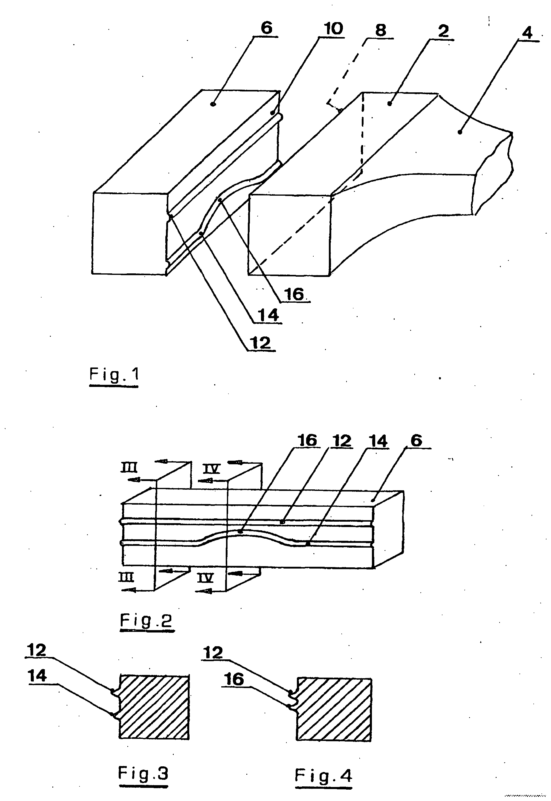
Figure 1 is an isometric perspective view of two jaws of an ultrasonic sealing device
for a top fin of a gable-topped carton;
Figure 2 is an isometric perspective view of one of the jaws of Figure 1;
Figure 3 shows a cross-section taken on the plane III-III of Figure 2;
Figure 4 shows a cross-section taken on the plane IV-IV of Figure 2; and
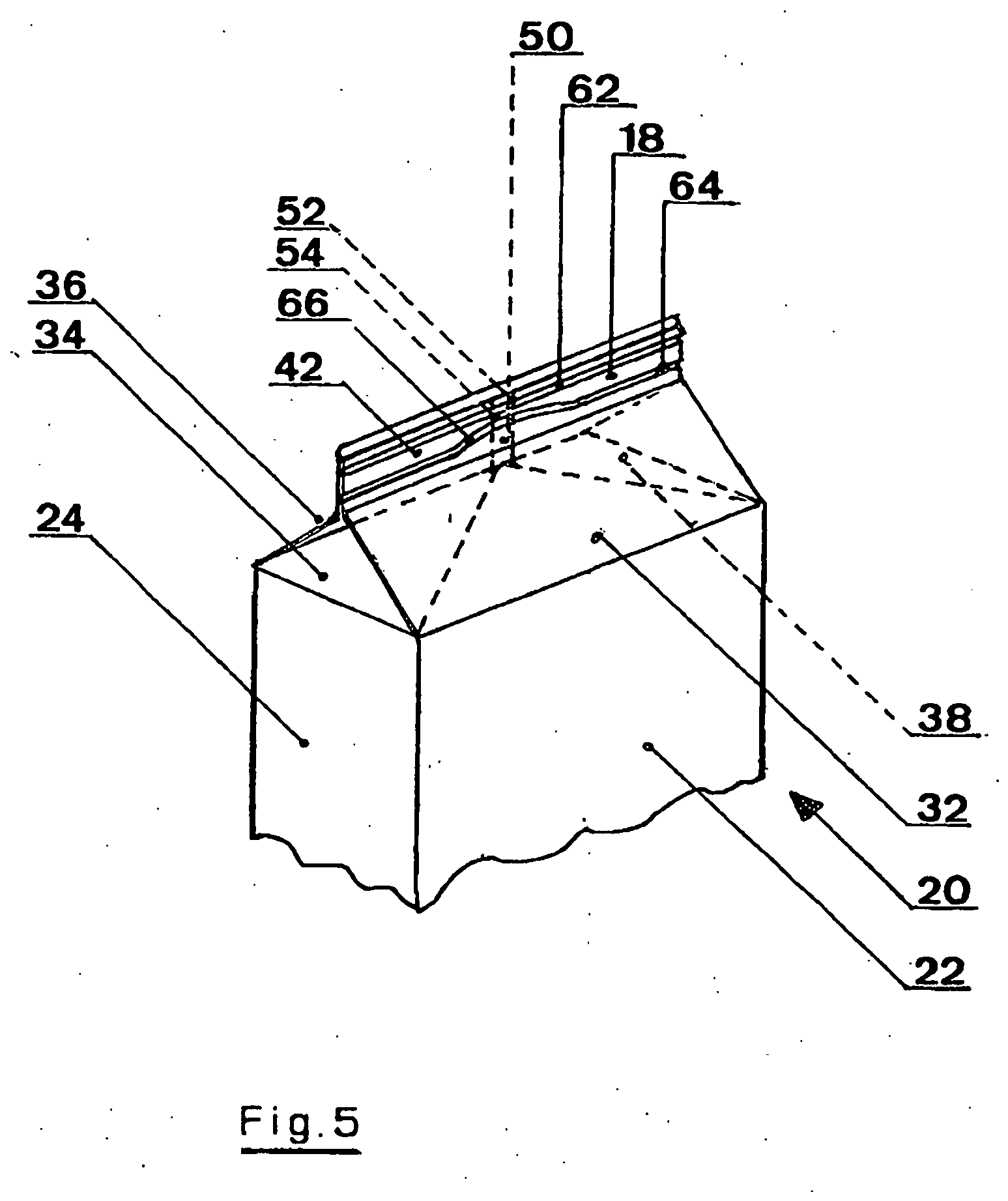
Figure 5 is an isometric perspective view of an upper portion of a gable-top carton
whereof the top fin has been sealed by the two jaws according to Figure 1.
[0020] Referring to Figures 1 to 4, the two jaws for ultrasonic sealing consist of a jaw
2 constituting the outer end portion of an ultrasonic horn 4, and a jaw 6 constituting
an anvil. The jaw 2 has an active sealing surface 8 which is planar, whilst the co-operating
active sealing surface 10 of the anvil 6 is planar except for upper and lower ribs
12 and 14 each extending the length of the surface 10. The upper rib 12 is linear
and horizontal, whilst the lower rib 14 is linear and horizontal except for an upwardly
bowed middle portion 16 thereof.
[0021] The two jaws 2 and 6 serve to render gas-and-liquid tight a top fin 18 of a conventional
gable-top carton, 20 shown in Figure 5. The carton 20 is made of a laminate including
a paperboard substrate and innermost and outermost moisture barrier layers of thermoplastics,
possibly with the interposition of an oxygen barrier layer of, for example, aluminium
foil or ethylene vinyl alcohol (EVOH) between the paperboard layer and the innermost
moisture barrier layer.
[0022] It will be understood that the carton 20 includes a loop of side panels 22,24, etc.,
a loop of top, obturating panels 32,34,36,38, etc., and a loop of sealing panels 42,
etc., providing the sealing fin 18. It will also be understood that the sealing fin
18 consists of two outer sealing panels (of which one is 42) and two inner sealing
panels which are sandwiched between the outer sealing panels and each folded upon
itself and which are so disposed between the two outer sealing panels as unwantedly
to produce a central incipient channel 50 bounded by the two outer sealing panels
and inwardly folded edges 52 and 54 of the respective inner sealing panels. It will
also be understood that, upon clamping of the fin 18 between the jaws 2 and 6 for
sealing of the fin, the ribs 12 and 14 produce in the outer surface of the sealing
panel 42, as shown in Figure 5, corresponding furrows 62 and 64, both of which extend
over the whole length of the fin 18 at levels where the inner sealing panels are sandwiched
between the outer sealing panels, so as to seal the top fin 18 in a gas-and liquid-tight
manner along its whole length. The upwardly bowed middle portion 16 of the rib 14
produces a correspondingly upwardly bowed middle portion 66 of the furrow 64. The
obturating panel 32 or 36 is provided with a pour spout fitment (not shown).
[0023] The upward bowing of the middle portion 66 of the furrow 64 has two advantages. The
first is that it takes the sealing action of the rib 14 upwardly away from the lower
ends of the edges 52 and 54, where the multi-plane folding of the laminate of the
carton 20 is more likely to produce weaknesses in gas-and liquid-tightness of the
carton 20 and so avoids exacerbating any such weaknesses through the application of
sealing pressure to such weaknesses.
[0024] A second advantage is that the bowed middle portion 66 tends to displace upwardly
towards the sealing furrow 62 innermost thermoplastics material of the laminate of
the carton 20 in the region of that part of the incipient channel 50 directly above
the portion 66, so that that material tends to be forced into the channel 50 at its
section between the furrow 62 and the portion 66, so to promote gas-and liquid-tight
sealing of that channel 50.
[0025] It will be appreciated that the system described with reference to the drawings is
applicable also to a slant-top carton, as well as to a gable-bottom or slant-bottom
carton.
[0026] The present system is particularly applicable where sealing of the sealing fin may
have to be through liquid product residues remaining on the insides of the sealing
panels of the fin after filling of the carton.
1. A jaw for use in sealing of an end fin of a packaging carton, which fin (18) comprises
first (42) and second outer sealing panels and first and second inner sealing panels
which are sandwiched between said outer sealing panels and each folded upon itself
and which are so disposed between said outer sealing panels (42) as to produce a central
incipient channel (50) bounded by said outer sealing panels (42) and inwardly folded
edges (.52,54) of the respective inner sealing panels, said jaw (6) comprising a sealing
rib (14) extending longitudinally of an active face (10) of said jaw (6), wherein
said sealing rib (14) includes a bowed middle portion (16), the arrangement is such
that, during the sealing, the bowing of said middle portion (16) is away from the
middle of the carton (20), and there are substantially no sealing protrusions to that
side of said rib (14) which, during the sealing, is towards the middle of the carton
(20), and further comprising, to that side of the rib (14) which, during the sealing,
is away from the middle of the carton (20), a second sealing rib (12) extending longitudinally
of said active face (10) and closely adjacent to said bowed middle portion (16).
2. A jaw according to claim 1, wherein said second sealing rib (12) is substantially
co-extensive with the first-mentioned sealing rib (14) longitudinally thereof.
3. A jaw according to claim 1 or 2, wherein said second sealing rib (12) is rectilinear.
4. A jaw according to any preceding claim and in the form of an anvil (6) for bearing
pressure produced by an ultrasonic sealing horn (4).
5. A method of sealing an end fin of a packaging carton, which fin (18) comprises first
(42) and second outer sealing panels and first and second inner sealing panels which
are sandwiched between said outer sealing panels and each folded upon itself and which
are so disposed between said outer sealing panels (42) as to produce a central incipient
channel (50) bounded by said outer sealing panels (42) and inwardly folded edges (52,54)
of the respective inner sealing panels, comprising temporarily clamping said fin (18)
between sealing jaws (2,6) and thereby forming, along said fin (18), a line (64) of
pressure and thereby a seal among said outer sealing panels and said inner sealing
panels, wherein said line (64) and thereby said seal (64) include a middle portion
(66) bowed away from the middle of the carton (20), thereby promoting closure of said
central incipient channel (50), and the degree of sealing pressure produced by said
clamping is greater at said line (64) than any produced by said jaws (2,6) at any
location between said line (64) and the middle of said carton (20), the method further
comprising, simultaneously with said forming, of said line (64), forming along said
fin (18) a second line (62) of pressure extending closely adjacent to the first-mentioned
line (64) of pressure and among said outer sealing panels (42) and said inner sealing
panels, said second line (62) of pressure being to that side of the first-mentioned
line (64) of pressure away from the middle of the carton (20).
6. A method according to claim 5, wherein said second line (62) of pressure is formed
co-extensively with the first-mentioned line (64) of pressure longitudinally thereof.
7. A method according claim 5 or 6, wherein said second line (62) of pressure is rectilinear.
8. A method according to any one of claims 5 to 7, wherein said sealing is ultrasonic.
9. A method according to claim 8, wherein the or each line (62,64) of pressure is produced
by forming of a correspondingly shaped furrow (62,64) in an outer surface of one (42)
of the outer sealing panels by a correspondingly shaped rib (12,14) on one (6) of
the jaws (2,6) which constitutes an anvil (6) co-operating with an ultrasonic horn
(4).
10. A packaging carton including an end fin (18) comprising first (42) and second outer
sealing panels and first and second inner sealing panels which are sandwiched between
said outer sealing panels and each folded upon itself and which are so disposed between
said outer sealing panels as to produce a central incipient channel (50) bounded by
said outer sealing panels and inwardly folded edges (52,54) of the respective inner
sealing panels, and a linear seal (64) formed among said outer sealing panels and
said inner sealing panels, wherein said linear seal (64) includes a middle portion
(66) bowed away from the middle of the carton (20), whereby closure of said central
incipient channel (50) has been promoted, and sealing tightness per unit area at said
linear seal (64) is greater than at any location between said linear seal (64) and
the middle of said carton (20), and further comprising a second linear seal (62) formed,
among said outer sealing panels and said inner sealing panels, along said fin (18)
and extending closely adjacent to the first-mentioned linear seal (64), said second
linear seal (62) being located to that side of the first-mentioned linear seal (64)
away from the middle of said carton (20).
11. A carton according to claim 10, wherein said second linear seal (62) is co-extensive
with the first-mentioned linear seal (64) longitudinally thereof.
12. A carton according to claim 11, wherein said second linear seal (62) is rectilinear.
1. Backe zur Verwendung beim Versiegeln eines Endstegs einer Verpackungsschachtel, wobei
der Steg (18) eine erste (42) und eine zweite äußere Siegelplatte und eine erste und
eine zweite innere Siegelplatte umfasst, welche zwischen den äußeren Siegelplatten
sandwichartig eingeschlossen und jeweils auf sich selbst gefaltet sind und welche
zwischen den äußeren Siegelplatten (42) angeordnet sind, um einen mittigen Anfangskanal
(50) herzustellen, der durch die äußeren Siegelplatten (42) und nach innen gefaltete
Ränder (52, 54) der jeweiligen inneren Siegelplatten gebunden ist, wobei die Backe
(6) eine Siegelrippe (14) umfasst, die sich längs zu einer aktiven Fläche (10) der
Backe (6) erstreckt, wobei die Siegelrippe (14) einen gekrümmten Mittenabschnitt (16)
aufweist, wobei die Anordnung derart ausgebildet ist, dass, während des Versiegelns,
die Krümmung des Mittenabschnitts (16) von der Mitte der Schachtel (20) weg weist
und es im Wesentlichen keine Siegelvorsprünge zu dieser Seite der Rippe (14) gibt,
welche, während des Versiegelns, zu der Mitte der Schachtel (20) hin weist, und wobei
sie ferner, zu dieser Seite der Rippe (14), welche, während des Versiegelns, von der
Mitte der Schachtel (20) weg weist, eine zweite Siegelrippe (12) umfasst, die sich
längs zu der aktiven Fläche (10) und eng benachbart zu dem gekrümmten Mittenabschnitt
(16) erstreckt.
2. Backe nach Anspruch 1, wobei die zweite Siegelrippe (12) mit der zuerst erwähnten
Siegelrippe (14) längs davon im Wesentlichen koextensiv ist.
3. Backe nach Anspruch 1 oder 2, wobei die zweite Siegelrippe (12) geradlinig ist.
4. Backe nach einem der vorhergehenden Ansprüche und in Form eines Ambosses (6) für Auflagedruck,
der durch eine Ultraschall-Siegelsonotrode (4) erzeugt wird.
5. Verfahren zum Versiegeln eines Endstegs einer Verpackungsschachtel, wobei der Steg
(18) eine erste (42) und eine zweite äußere Siegelplatte und eine erste und eine zweite
innere Siegelplatte umfasst, welche zwischen den äußeren Siegelplatten sandwichartig
eingeschlossen und auf sich selbst gefaltet sind und welche zwischen den äußeren Siegelplatten
(42) angeordnet sind, um einen mittigen Anfangskanal (50) herzustellen, der durch
die äußeren Siegelplatten (42) und nach innen gefaltete Ränder (52, 54) der jeweiligen
inneren Siegelplatten gebunden ist, umfassend ein vorübergehendes Klemmen des Stegs
(18) zwischen den Siegelbacken (2, 6) und dadurch Bilden, entlang des Stegs (18),
einer Druckleitung (64) und dadurch einer Versiegelung zwischen den äußeren Siegelplatten
und den inneren Siegelplatten, wobei die Leitung (64) und dadurch die Versiegelung
(64) einen Mittenabschnitt (66) aufweisen, der von der Mitte der Schachtel (20) weg
gekrümmt ist, wodurch ein Verschluss des mittigen Anfangskanals (50) gefördert wird
und der Grad des Siegeldrucks, der durch das Klemmen erzeugt wird, an der Leitung
(64) größer ist als einer, der durch die Backen (2, 6) an einer Stelle zwischen der
Leitung (64) und der Mitte der Schachtel (20) erzeugt wird, wobei das Verfahren ferner,
gleichzeitig mit dem Bilden der Leitung (64), ein Bilden entlang des Stegs (18) einer
zweiten Druckleitung (62) umfasst, die sich eng benachbart zu der zuerst erwähnten
Druckleitung (64) und zwischen den äußeren Siegelplatten (42) und den inneren Siegelplatten
erstreckt, wobei die zweite Druckleitung (62) zu dieser Seite der zuerst erwähnten
Druckleitung (64) von der Mitte der Schachtel (20) weg weist.
6. Verfahren nach Anspruch 5, wobei die zweite Druckleitung (62) mit der zuerst erwähnten
Druckleitung (64) längs davon koextensiv gebildet ist.
7. Verfahren nach Anspruch 5 oder 6, wobei die zweite Druckleitung (62) geradlinig ist.
8. Verfahren nach einem der Ansprüche 5 bis 7, wobei die Versiegelung eine Ultraschallversiegelung
ist.
9. Verfahren nach Anspruch 8, wobei die oder jede Druckleitung (62, 64) durch Bilden
einer entsprechend geformten Furche (62, 64) in einer äußeren Fläche von einer (42)
der äußeren Siegelplatten durch eine entsprechend geformte Rippe (12, 14) auf einer
(6) der Backen (2, 6), welche einen Amboss (6) bildet, der mit einer Ultraschallsonotrode
(4) zusammenwirkt, hergestellt wird.
10. Verpackungsschachtel, aufweisend einen Endsteg (18), umfassend eine erste (42) und
eine zweite äußere Siegelplatte und eine erste und eine zweite innere Siegelplatte,
welche zwischen den äußeren Siegelplatten sandwichartig eingeschlossen und jeweils
auf sich selbst gefaltet sind und welche zwischen den äußeren Siegelplatten angeordnet
sind, um einen mittigen Anfangskanal (50) herzustellen, der durch die äußeren Siegelplatten
und nach innen gefaltete Ränder (52, 54) der jeweiligen inneren Siegelplatten gebunden
ist, und eine lineare Versiegelung (64), die zwischen den äußeren Siegelplatten und
den inneren Siegelplatten gebildet ist, wobei die lineare Versiegelung (64) einen
Mittenabschnitt (66) aufweist, der von der Mitte der Schachtel (20) weg gekrümmt ist,
wodurch ein Verschluss des mittigen Anfangskanals (50) gefördert wurde und eine Dichtigkeit
pro Flächeneinheit an der linearen Versiegelung (64) größer ist als an einer Stelle
zwischen der linearen Versiegelung (64) und der Mitte der Schachtel (20), und ferner
umfassend eine zweite lineare Versiegelung (62), die, zwischen den äußeren Siegelplatten
und den inneren Siegelplatten, entlang des Stegs (18) und sich eng benachbart zu der
zuerst erwähnten linearen Versiegelung (64) erstreckend, gebildet ist, wobei sich
die zweite lineare Versiegelung (62) zu dieser Seite der zuerst erwähnten linearen
Versiegelung (64) von der Mitte der Schachtel (20) weg befindet.
11. Schachtel nach Anspruch 10, wobei die zweite lineare Versiegelung (62) mit der zuerst
erwähnten linearen Versiegelung (64) längs davon koextensiv ist.
12. Schachtel nach Anspruch 11, wobei die zweite lineare Versiegelung (62) geradlinig
ist.
1. Mâchoire destinée à sceller une ailette d'extrémité d'un carton d'emballage, ladite
ailette (18) comprenant des premier (42) et deuxième panneaux de soudage extérieurs
et des premier et deuxième panneaux de scellage intérieurs, lesquels sont pris en
sandwich entre lesdits panneaux de scellage extérieurs et respectivement repliés sur
eux-mêmes, et lesquels sont disposés entre lesdits panneaux de scellage extérieurs
(42) de manière à créer un canal naissant central (50) délimité par lesdits panneaux
de scellage extérieurs (42) et des bords pliés vers l'intérieur (52, 54) des panneaux
de scellage intérieurs respectifs, ladite mâchoire (6) comprenant une nervure de scellage
(14) s'étendant le long d'une face active (10) de ladite mâchoire (6), dans laquelle
ladite nervure de scellage (14) comprend une partie centrale incurvée (16), l'arrangement
étant tel que pendant le scellage, l'incurvation de ladite partie centrale (16) se
trouve à distance du milieu du carton (20), et que substantiellement aucune saillie
de scellage n'est présente sur le côté de ladite nervure (14) tourné vers le milieu
du carton (20) pendant le scellage, et comprenant en outre, sur le côté de la nervure
(14) opposé au milieu du carton (20) pendant le scellage, une deuxième nervure de
scellage (12) s'étendant le long de ladite face active (10) et de façon étroitement
à adjacente à ladite partie centrale incurvée (16).
2. Mâchoire selon la revendication 1, dans laquelle ladite nervure de scellage (12) est
substantiellement coextensive avec la nervure de scellage (14) mentionnée en premier,
le long de celle-ci.
3. Mâchoire selon la revendication 1 ou 2, dans laquelle ladite deuxième nervure de scellage
(12) est rectiligne.
4. Mâchoire selon l'une quelconque des revendications précédentes, réalisée sous la forme
d'une enclume (6) pour supporter la pression produite par une sonotrode à ultrasons
(4).
5. Procédé de scellage d'une ailette d'extrémité d'un carton d'emballage, ladite ailette
(18) comprenant des premier (42) et deuxième panneaux de soudage extérieurs et des
premier et deuxième panneaux de scellage intérieurs, lesquels sont pris en sandwich
entre lesdits panneaux de scellage extérieurs et respectivement repliés sur eux-mêmes,
et lesquels sont disposés entre lesdits panneaux de scellage extérieurs (42) de manière
à créer un canal naissant central (50) délimité par lesdits panneaux de scellage extérieurs
(42) et des bords pliés vers l'intérieur (52, 54) des panneaux de scellage intérieurs
respectifs, comprenant le serrage temporaire de ladite ailette (18) entre des mâchoires
de scellage (2, 6) et formant ainsi, le long de ladite ailette (18), une ligne de
pression (64) et donc un joint entre lesdits panneaux de scellage extérieurs et lesdits
panneaux de scellage intérieurs, dans lequel ladite ligne (64) et donc ledit joint
(64) comprennent une partie centrale (66) incurvée à l'opposé du milieu du carton
(20), favorisant ainsi la fermeture dudit canal naissant central (50), et le degré
de pression de scellage produit par ledit serrage est plus élevé au niveau de ladite
ligne (64) que n'importe lequel produit par lesdites mâchoires (2, 6) à n'importe
quel endroit entre ladite ligne (64) et le milieu dudit carton (20), le procédé comprenant
en outre, simultanément avec ladite formation de ladite ligne (64), la formation d'une
deuxième ligne de pression (62) le long de ladite ailette (18), laquelle s'étend de
manière étroitement adjacente à la ligne de pression (64) mentionnée en premier, et
entre lesdits panneaux de scellage extérieurs (42) et lesdits panneaux de scellage
intérieurs, ladite deuxième ligne de pression (62) se trouvant sur le côté de la ligne
de pression (64) mentionnée en premier opposé au milieu du carton (20).
6. Procédé selon la revendication 5, dans lequel ladite deuxième ligne de pression (62)
est formée de manière coextensive avec la ligne de pression (64) mentionnée en premier,
le long de celle-ci.
7. Procédé selon la revendication 5 ou 6, dans lequel ladite deuxième ligne de pression
(62) est rectiligne.
8. Procédé selon l'une quelconque des revendications 5 à 7, dans lequel ledit scellage
est ultrasonique.
9. Procédé selon la revendication 8, dans lequel la ou chaque ligne de pression (62,
64) est réalisée en formant un sillon de forme correspondante (62, 64) dans une surface
extérieure de l'un (42) des panneaux de scellage extérieurs au moyen d'une nervure
de forme correspondante (12, 14) sur l'une (6) des mâchoires (2, 6) constituant une
enclume (6) coopérant avec une sonotrode à ultrasons (4).
10. Carton d'emballage comprenant une ailette d'extrémité (18) comprenant des premier
(42) et deuxième panneaux de soudage extérieurs et des premier et deuxième panneaux
de scellage intérieurs, lesquels sont pris en sandwich entre lesdits panneaux de scellage
extérieurs et respectivement repliés sur eux-mêmes, et lesquels sont disposés entre
lesdits panneaux de scellage extérieurs de manière à créer un canal naissant central
(50) délimité par lesdits panneaux de scellage extérieurs et des bords pliés vers
l'intérieur (52, 54) des panneaux de scellage intérieurs respectifs, et un joint linéaire
(64) formé le long desdits panneaux de scellage extérieurs et desdits panneaux de
scellage intérieurs, dans lequel ledit joint linéaire (64) comprend une partie centrale
(66) incurvée à l'opposé du milieu du carton (20), moyennant quoi la fermeture dudit
canal naissant central (50) est favorisée, et le scellage par unité de surface au
niveau dudit joint linéaire (64) est plus fort qu'à n'importe quel endroit entre ledit
joint linéaire (64) et le milieu dudit carton (20), et comprenant en outre un deuxième
joint linéaire (62) formé, entre lesdits panneaux de scellage extérieurs et lesdits
panneaux de scellage intérieurs, le long de ladite ailette (18) et s'étendant de manière
étroitement adjacente au joint linéaire (64) mentionné en premier, ledit deuxième
joint linéaire (62) se trouvant sur le côté du joint linéaire (64) mentionné en premier
opposé au milieu dudit carton (20).
11. Carton selon la revendication 10, dans lequel ledit deuxième joint linéaire (62) est
coextensif avec le joint linéaire (62) mentionné en premier, le long de celui-ci.
12. Carton selon la revendication 11, dans lequel ledit deuxième joint linéaire (62) est
rectiligne.
REFERENCES CITED IN THE DESCRIPTION
This list of references cited by the applicant is for the reader's convenience only.
It does not form part of the European patent document. Even though great care has
been taken in compiling the references, errors or omissions cannot be excluded and
the EPO disclaims all liability in this regard.
Patent documents cited in the description