| (19) |
 |
|
(11) |
EP 2 855 230 B1 |
| (12) |
EUROPEAN PATENT SPECIFICATION |
| (45) |
Mention of the grant of the patent: |
|
09.10.2019 Bulletin 2019/41 |
| (22) |
Date of filing: 03.06.2013 |
|
| (51) |
International Patent Classification (IPC):
|
| (86) |
International application number: |
|
PCT/FI2013/050596 |
| (87) |
International publication number: |
|
WO 2013/182746 (12.12.2013 Gazette 2013/50) |
|
| (54) |
RAIL VEHICLE
SCHIENENFAHRZEUG
VÉHICULE FERROVIAIRE
|
| (84) |
Designated Contracting States: |
|
AL AT BE BG CH CY CZ DE DK EE ES FI FR GB GR HR HU IE IS IT LI LT LU LV MC MK MT NL
NO PL PT RO RS SE SI SK SM TR |
| (30) |
Priority: |
04.06.2012 FI 20125604
|
| (43) |
Date of publication of application: |
|
08.04.2015 Bulletin 2015/15 |
| (73) |
Proprietor: Helsingin kaupungin liikenneliikelaitos |
|
00099 Helsingin kaupunki (FI) |
|
| (72) |
Inventor: |
|
- HEIKKILÄ, Ollipekka
00099 Helsingin kaupunki (FI)
|
| (74) |
Representative: Kolster Oy Ab |
|
(Salmisaarenaukio 1)
P.O. Box 204
00181 Helsinki
00181 Helsinki (FI) |
| (56) |
References cited: :
EP-A1- 0 692 421
EP-A1- 1 074 448
WO-A1-95/34435
US-A- 5 036 774
US-B1- 6 167 814
|
EP-A1- 0 915 000
EP-A2- 1 741 610
FR-A1- 2 549 436
US-A1- 2001 052 305
|
|
| |
|
|
|
|
| |
|
| Note: Within nine months from the publication of the mention of the grant of the European
patent, any person may give notice to the European Patent Office of opposition to
the European patent
granted. Notice of opposition shall be filed in a written reasoned statement. It shall
not be deemed to
have been filed until the opposition fee has been paid. (Art. 99(1) European Patent
Convention).
|
Background of the invention
[0001] The invention relates to a rail vehicle, a low-floor tram in particular, comprising
a connecting car connected between two car units and supporting these car units and
being supported on a bogie unit of its own.
[0002] Tram solutions are known wherein all cars with bogies are provided with fixed bogies
that do not turn with respect to a car or that are only slightly flexible in a direction
of rotation (henceforth "fixed bogie"), which results in high lateral accelerations
of single cars.
[0003] In some trams, a central car section (the connecting car) is provided with one fixed
bogie and the car units connected thereto are each provided with a bogie allowed to
pivot around one fulcrum.
[0004] Solutions are also used wherein all bogies are bogies pivoting around one fulcrum
so that the connecting car is provided with two bogies while end cars are each provided
with one bogie. The problem with this is the limited length of the cars and the large
number of bogies with respect to the length of the combination.
[0005] A structure has also been implemented which has two bogies with two fulcrums, wherein
consecutively connected cars are allowed to pivot on said fulcrums, the ends of the
combination being provided with bogies pivoting around one fulcrum.
[0006] Hybrid structures also exist with for instance two fixed bogies and a combination
of various bogies which have one fulcrum and are located higher than other bogies,
in which case the problem is the plurality of bogies of various types and stair structures
in a passenger cabin necessitated by the bogies.
[0007] Some of the above-described bogies interconnecting the cars are bogies which in connection
with rail vehicles are called Jacob-type bogies on which the consecutive cars are
supported and articulated. A Jacob-type bogie may be fastened directly to the interconnected
cars through separate fulcrums or through an intermediate body (a connecting car or
an articulated section) articulating the cars with one another so that the bogie pivots
around one fulcrum only. In each of the above-mentioned situations the bogie structure,
including the bellows sealing the car body parts together, requires a lot of space
in a vertical direction.
[0008] A Jacob-type bogie pivoting around one fulcrum would be advantageous also in a low-floor
tram but so far it has been impossible to implement it therein in an appropriate manner.
[0009] Document
EP 1 074 448 A1 discloses a track-bound vehicle, especially railway vehicle for regional transport,
the vehicle having at least three coupled wagon boxes horizontally rotatably supported
on a corresponding running gear. A control system controls the rotation angle of the
last wagon box relative to its associated running gear depending on that of the first
wagon box.
SUMMARY OF THE INVENTION
[0010] An object of the invention is thus to solve the problems described above. This object
is achieved by the rail vehicle according to the invention, which is mainly characterized
in that the connecting car is supported on its bogie unit such that it pivots substantially
freely around one fulcrum in a horizontal plane, and equipment is arranged between
the connecting car and the car units connected thereto for keeping horizontal turning
angles between both connected car units and the connecting car almost equal in magnitude.
[0011] Preferably, the equipment for keeping the turning angles almost equal in magnitude
consists of a lever mechanism comprising a first bar articulatedly connected to one
car unit, a second bar articulatedly connected to another car unit, and an idler pivotally
mounted to the connecting car, the first bar and the second bar being articulated
on opposite sides of a fulcrum of the idler at selected distances from the fulcrum,
and whereby the first bar and the second bar as well as the idler are with respect
to a longitudinal vertical centre plane of the rail vehicle located on the same side
of the rail vehicle.
[0012] The above-mentioned preferred embodiment of the invention is thus based on installing
the lever mechanism such that it divides the angles of two long car modules and a
short connecting car module mounted therebetween on a bogie pivoting freely around
one fulcrum into angles of equal magnitudes. The mechanism may be a so-called Watt
mechanism, for instance.
[0013] The equipment for keeping said turning angles equal in magnitude may also be implemented
in another manner mechanically, hydraulically, pneumatically, electromechanically,
etc. The main thing is that it keeps the horizontal angles of the connecting car freely
pivoting on its bogie equal in magnitude with respect to the car units in front of
and behind it.
[0014] These and other preferred embodiments of the invention are disclosed in the dependent
claims.
[0015] As compared with the use of a bogie structure with two fulcrums and the use of a
non-pivoting bogie structure, the solution related to the use of the bogie structure
with one fulcrum according to the invention enables smaller lateral forces and lateral
accelerations both in the bogie structure and in the actual car structure to be achieved.
The smaller lateral forces and lateral accelerations enable a lighter and longer lasting
car and bogie structure, which means considerable savings in manufacturing, maintenance
and energy costs. Moreover, the smaller lateral forces of wheels reduce wear and tear
of a wheel ring flange and railway curves, which means considerable savings in maintenance
costs. At the same time, the risk of derailment is reduced and passenger comfort increases.
By providing the rail vehicle with bogies of the same type throughout, cost savings
in design, manufacturing and spare part costs as well as in car and railway track
maintenance costs are achieved. The invention also enables the railway track to be
built in a smaller street space since owing to the turning bogies, a less extensive
transition curve (clothoid) will suffice before the actual railway curve.
List of figures
[0016] The invention is now described in closer detail by means of some preferred embodiments
and with reference to the accompanying drawings, in which
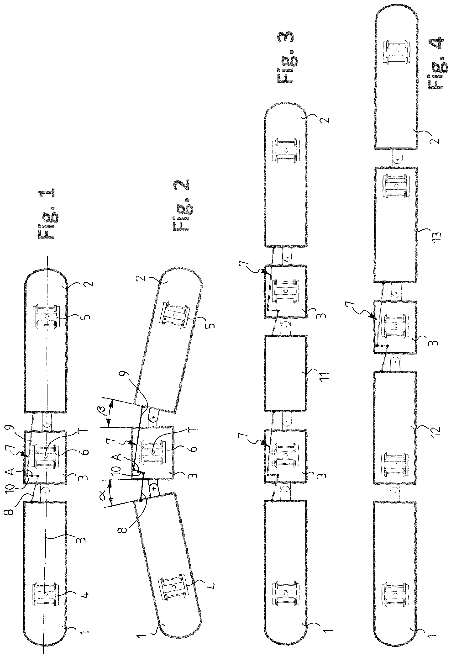
Figure 1 shows a tram provided with two car units and one connecting car therebetween;
Figure 2 shows the tram according to Figure 1 in a curve;
Figure 3 shows a tram wherein a car unit with no bogie is supported between two connecting
cars and car units with bogies are connected to other ends of the connecting cars;
Figure 4 shows a tram wherein two car units provided with bogies are connected to
both sides of a connecting car; and
Figure 5 shows a modification of the tram according to Figure 1.
Detailed description of the invention
[0017] Figures 1 and 2 show a low-floor tram comprising two car units 1 and 2 and, connected
therebetween, a connecting car 3 supporting these car units. The car units 1 and 2
are provided with bogies 4 and 5, and the connecting car 3 is provided with a bogie
6 on which the connecting car 3 is supported by its middle such that it pivots around
one fulcrum T substantially freely in a horizontal plane. In addition, between the
connecting car 3 and the car units 1 and 2 connected thereto, equipment 7 is arranged
for keeping horizontal turning angles α and β between the both connected car units
1 and 2 and the connecting car 3 almost equal in magnitude.
[0018] The equipment for keeping the turning angles α and β equal in magnitude consists
of a lever mechanism 7 comprising a first bar 8 articulatedly connected to one car
unit 1, a second bar 9 articulatedly connected to the the other car unit 2, and an
idler 10 which, in this example, is turnably pivotally mounted in a horizontal plane
(may, of course, also be in a vertical plane) to the connecting car 3, the first bar
8 and the second bar 9 being articulated on opposite sides of a fulcrum A of the idler
at selected distances from the fulcrum A, and whereby the first bar 8 and the second
bar 9 as well as the idler 10 are with respect to a longitudinal vertical centre plane
B of the rail vehicle located on the same side of the rail vehicle. In this example,
the first bar 8 and the second bar 9 differ in length, and the idler 10 is pivotally
mounted on one side of the fulcrum of the bogie 6 of the connecting car 3, as seen
in a longitudinal direction of the connecting car 3. The lever mechanism 7 may be
fastened to underside structures of the cars 1, 2, and 3, for instance. Of course,
the lever mechanism could also be constructed such that the first bar 8 and the second
bar 9 were equal in length and the idler 10 were pivotally mounted next to the fulcrum
of the bogie 6 of the connecting car 3, as seen in a sideward direction.
[0019] It can be seen in Figure 2 how the lever mechanism 7 keeps the angle α between the
car unit 1 and the connecting car 3 as well as the angle β between the car unit 2
and the connecting car 3 equal in magnitude in a curve drive situation, enabling the
above-described considerable advantages over the prior art to be achieved.
[0020] Figure 3 shows another tram embodiment according to the invention, wherein a car
unit 11 with no bogie is supported between two connecting cars 3 while the other ends
of the connecting cars 3 are connected to cars 1 and 2 provided with bogies and corresponding
to the car units of Figures 1 and 2. The lever mechanisms 7 between the connecting
cars 3 and the car units 1, 2, and 11 correspond to the lever mechanisms shown in
Figures 1 and 2 and, of course, guide the turning angles between the cars 1, 2, 3,
and 11 as in Figures 1 and 2.
[0021] Figure 4 shows yet another tram embodiment according to the invention, wherein two
car units 1, 12 and 2, 13, provided with bogies, are connected on each side of the
connecting car 3, in which case the end cars 1 and 2 are similar to those shown in
the previous figures.
[0022] The equipment for keeping said turning angles α and β almost equal in magnitude may
also be implemented in a manner other than by means of the lever mechanism 7 described
above. One such example is shown in Figure 5 wherein equipment 70 for keeping the
turning angles equal in magnitude comprises hydraulic or pneumatic cylinders 80 and
90 installed between the connecting car 3 and the car units 1 and 2 connected thereto,
whereby the cylinder 80 located in front of the connecting car 3 and the cylinder
90 located at the back of the connecting car 3 reside on opposite sides of the longitudinal
vertical centre plane B of the rail vehicle. In place of the cylinders 80 and 90,
an electromechanical arrangement could also be provided, as one of many alternative
implementations for controlling the turning angles in a controlled manner. More cylinders
80 and 90 may also be provided on both sides in order to ensure operation.
[0023] The above description of the invention is only intended to illustrate the basic idea
according to the invention. A person skilled in the art may thus vary its details
within the scope of the accompanying claims. Thus, for instance, the number of interconnected
cars may vary as necessary and differ from the above-described alternatives within
the limits set by the invention. The invention may also be applied to rail vehicles
other than trams, such as to high speed tram equipment.
1. A rail vehicle, a low-floor tram in particular, comprising a connecting car (3) connected
between two car units (1, 2, 11, 12, 13) and supporting these car units and being
supported on a bogie unit (6) of its own, characterized in that the connecting car (3) is supported on its bogie unit (6) such that it pivots substantially
freely around one fulcrum (T) in a horizontal plane, and equipment (7; 70) is arranged
between the connecting car (3) and the car units (1, 2, 11, 12, 13) connected thereto
for keeping horizontal turning angles (α, β) between both connected car units (1,
2, 11, 12, 13) and the connecting car (3) almost equal in magnitude.
2. A rail vehicle as claimed in claim 1, characterized in that the equipment for keeping the turning angles (α, β) almost equal in magnitude consists
of a lever mechanism (7) comprising a first bar (8) articulatedly connected to one
car unit (1, 11, 12), a second bar (9) articulatedly connected to another car unit
(2, 11, 13), and an idler (10) pivotally mounted to the connecting car (3), the first
bar (8) and the second bar (9) being articulated on opposite sides of a fulcrum (A)
of the idler at selected distances from the fulcrum (A), and whereby the first bar
(8) and the second bar (9) as well as the idler (10) are with respect to a longitudinal
vertical centre plane (B) of the rail vehicle located on the same side of the rail
vehicle.
3. A rail vehicle as claimed in claim 2, characterized in that the first bar (8) and the second bar (9) differ in length, and that the idler (10)
is pivotally mounted on a front or back side of a fulcrum of the bogie unit (6) of
the connecting car (3).
4. A rail vehicle as claimed in claim 2, characterized in that the first bar and the second bar are equal in length, and that the idler (10) is
pivotally mounted next to the fulcrum of the bogie unit (6) of the connecting car
(3).
5. A rail vehicle as claimed in claim 1, characterized in that the equipment for keeping the turning angles (α, β) almost equal in magnitude comprises
hydraulic or pneumatic cylinders (80, 90) installed between the connecting car (3)
and the car units (1, 2) connected thereto, whereby at least one cylinder (80) located
on one side of the connecting car and at least one cylinder (90) located on the other
side of the connecting car (3) reside on opposite sides of the longitudinal vertical
centre plane (B) of the rail vehicle.
6. A rail vehicle as claimed in claim 1, characterized in that the equipment for keeping the turning angles (α, β) almost equal in magnitude comprises
electromechanical mechanisms installed between the connecting car (3) and the car
units (1, 2, 11, 12, 13) connected thereto, whereby a mechanism located on one side
of the connecting car (3) and a mechanism located on the other side of the connecting
car (3) reside on opposite sides of the longitudinal vertical centre plane (B) of
the rail vehicle.
7. A rail vehicle as claimed in any one of the preceding claims, characterized in that car units without bogies are supported on both sides of the connecting car (3) and
car units with bogies are connected to the car units without bogies.
8. A rail vehicle as claimed in any one of claims 1 to 6, characterized in that the connecting car (3) is connected to the car units (1, 2, 12, 13) provided with
bogies (4, 5).
9. A rail vehicle as claimed in any one of claims 1 to 6, charac- terized in that between two connecting cars (3), a car unit (11) without a bogie is supported
and the other ends of the connecting cars are connected to car units (1, 2) with bogies
and, after these, possibly more car units with and/or without bogies.
1. Schienenfahrzeug, insbesondere eine Niederflurstraßenbahn, das einen Verbindungswagen
(3) umfasst, der zwischen zwei Wageneinheiten (1, 2, 11, 12, 13) verbunden ist und
diese Wageneinheiten stützt und auf einer eigenen Drehgestelleinheit (6) gestützt
ist, dadurch gekennzeichnet, dass der Verbindungswagen (3) auf seiner Drehgestelleinheit (6) derart gestützt ist, dass
er in einer horizontalen Ebene im Wesentlichen frei um einen Drehpunkt (T) schwenkt,
und eine Ausrüstung (7; 70) zum Halten von horizontalen Drehwinkeln (α, β) sowohl
zwischen den verbundenen Wageneinheiten (1, 2, 11, 12, 13) als auch dem Verbindungswagen
(3) in fast gleicher Größe zwischen dem Verbindungswagen (3) und den Wageneinheiten
(1, 2, 11, 12, 13), die damit verbunden sind, angeordnet ist.
2. Schienenfahrzeug nach Anspruch 1, dadurch gekennzeichnet, dass die Ausrüstung zum Halten der Drehwinkel (α, β) in fast gleicher Größe aus einem
Hebelmechanismus (7), der eine erste Stange (8), die gelenkig mit einer Wageneinheit
(1, 11, 12) verbunden ist, und eine zweite Stange (9), die gelenkig mit einer anderen
Wageneinheit (2, 11, 13) verbunden ist, und ein Leitrad (10), das schwenkbar am Verbindungswagen
(3) montiert ist, besteht, wobei die erste Stange (8) und die zweite Stange (9) auf
gegenüberliegenden Seiten des Drehpunkts (A) des Leitrads in ausgewählten Abständen
vom Drehpunkt (A) angelenkt sind und wodurch die erste Stange (8) und die zweite Stange
(9) sowie das Leitrad (10) mit Bezug auf eine vertikale zentrale Längsebene (B) des
Schienenfahrzeugs auf derselben Seite des Schienenfahrzeugs positioniert sind.
3. Schienenfahrzeug nach Anspruch 2, dadurch gekennzeichnet, dass die erste Stange (8) und die zweite Stange (9) von unterschiedlicher Länge sind und
dass das Leitrad (10) auf einer Vorder- oder einer Rückseite eines Drehpunkts der
Drehgestelleinheit (6) des Verbindungswagens (3) schwenkbar montiert ist.
4. Schienenfahrzeug nach Anspruch 2, dadurch gekennzeichnet, dass die erste Stange und die zweite Stange von gleicher Länge sind und dass das Leitrad
(10) neben dem Drehpunkt der Drehgestelleinheit (6) des Verbindungswagens (3) schwenkbar
montiert ist.
5. Schienenfahrzeug nach Anspruch 1, dadurch gekennzeichnet, dass die Ausrüstung zum Halten der Drehwinkel (α, β) in fast gleicher Größe hydraulische
oder pneumatische Zylinder (80, 90) umfasst, die zwischen dem Verbindungswagen (3)
und den Wageneinheiten (1, 2), die damit verbunden sind, installiert sind, wodurch
sich mindestens ein Zylinder (80), der auf einer Seite des Verbindungswagens positioniert
ist, und mindestens ein Zylinder (90), der auf der anderen Seite des Verbindungswagens
(3) positioniert ist, auf gegenüberliegenden Seiten der vertikalen zentralen Längsebene
(B) des Schienenfahrzeugs befinden.
6. Schienenfahrzeug nach Anspruch 1, dadurch gekennzeichnet, dass die Ausrüstung zum Halten der Drehwinkel (α, β) in fast gleicher Größe elektromechanische
Mechanismen umfasst, die zwischen dem Verbindungswagen (3) und den Wageneinheiten
(1, 2, 11, 12, 13), die damit verbunden sind, installiert sind, wodurch sich ein Mechanismus,
der auf einer Seite des Verbindungswagens (3) positioniert ist, und ein Mechanismus,
der auf der anderen Seite des Verbindungswagens (3) positioniert ist, auf gegenüberliegenden
Seiten der vertikalen zentralen Längsebene (B) des Schienenfahrzeugs befinden.
7. Schienenfahrzeug nach einem der vorhergehenden Ansprüche, dadurch gekennzeichnet, dass die Wageneinheiten ohne Drehgestelle auf beiden Seiten des Verbindungswagens (3)
gestützt sind, und Wageneinheiten mit Drehgestellen mit den Wageneinheiten ohne Drehgestelle
verbunden sind.
8. Schienenfahrzeug nach einem der Ansprüche 1 bis 6, dadurch gekennzeichnet, dass der Verbindungswagen (3) mit den Wageneinheiten (1, 2, 12, 13), die mit Drehgestellen
(4, 5) versehen sind, verbunden ist.
9. Schienenfahrzeug nach einem der Ansprüche 1 bis 6, dadurch gekennzeichnet, dass zwischen den Verbindungswagen (3) eine Wageneinheit (11) ohne ein Drehgestell gestützt
ist und die anderen Enden der Verbindungswagen mit Wageneinheiten (1, 2) mit Drehgestellen
verbunden sind, nach diesen möglicherweise weitere Wageneinheiten mit und/oder ohne
Drehgestelle.
1. Véhicule ferroviaire, en particulier un tramway à plancher surbaissé, comprenant une
voiture de connexion (3) connectée entre deux unités de voiture (1, 2, 11, 12, 13)
et supportant ces unités de voiture et étant supportée sur une unité de bogie (6)
d'elle-même, caractérisé en ce que la voiture de connexion (3) est supportée sur son unité de bogie (6) de sorte qu'elle
pivote sensiblement librement autour d'un pivot (T) dans un plan horizontal, et l'équipement
(7 ; 70) est agencé entre la voiture de connexion (3) et les unités de voiture (1,
2, 11, 12, 13) connectées à cette dernière pour maintenir des angles de rotation horizontaux
(α, β) entre les deux unités de voiture connectées (1, 2, 11, 12, 13) et la voiture
de connexion (3) presque égaux du point de vue de la grandeur.
2. Véhicule ferroviaire selon la revendication 1, caractérisé en ce que l'équipement pour maintenir les angles de rotation (α, β) presque égaux du point
de vue de la grandeur se compose d'un mécanisme de levier (7) comprenant une première
barre (8) connectée, par articulation, à une unité de voiture (1, 11, 12), une second
barre (9) connectée, par articulation, à une autre unité de voiture (2, 11, 13) et
une poulie folle (10) montée, de manière pivotante sur la voiture de connexion (3),
la première barre (8) et la seconde barre (9) étant articulées sur les côtés opposés
d'un pivot (A) de la poulie folle à des distances sélectionnées du pivot (A), et moyennant
quoi la première barre (8) et la seconde barre (9) ainsi que la poulie folle (10)
sont positionnées, par rapport à un plan central vertical longitudinal (B) du véhicule
ferroviaire, du même côté du véhicule ferroviaire.
3. Véhicule ferroviaire selon la revendication 2, caractérisé en ce que la première barre (8) et la seconde barre (9) sont différentes du point de vue de
la longueur, et en ce que la poulie folle (10) est montée, de manière pivotante sur un côté avant ou arrière
d'un pivot de l'unité de bogie (6) de la voiture de connexion (3).
4. Véhicule ferroviaire selon la revendication 2, caractérisé en ce que la première barre et la seconde barre sont identiques en longueur, et en ce que la poulie folle (10) est montée de manière pivotante à côté du pivot de l'unité de
bogie (6) de la voiture de connexion (3).
5. Véhicule ferroviaire selon la revendication 1, caractérisé en ce que l'équipement pour maintenir les angles de rotation (α, β) presque égaux en magnitude
comprend des cylindres hydrauliques ou pneumatiques (80, 90) installés entre la voiture
de connexion (3) et les unités de voiture (1, 2) raccordées à cette dernière, moyennant
quoi au moins un cylindre (80) positionné d'un côté de la voiture de connexion et
au moins un cylindre (90) positionné de l'autre côté de la voiture de connexion (3),
résident sur les côtés opposés du plan central vertical longitudinal (B) du véhicule
ferroviaire.
6. Véhicule ferroviaire selon la revendication 1, caractérisé en ce que l'équipement pour maintenir les angles de rotation (α, β) presque égaux du point
de vue de la grandeur comprend des mécanismes électromécaniques installés entre la
voiture de connexion (3) et les unités de voitures (1, 2, 11, 12, 13) raccordées à
cette dernière, moyennant quoi un mécanisme positionné d'un côté de la voiture de
connexion (3) et un mécanisme positionné de l'autre côté de la voiture de connexion
(3) résident sur les côtés opposés du plan central vertical longitudinal (B) du véhicule
ferroviaire.
7. Véhicule ferroviaire selon l'une quelconque des revendications précédentes, caractérisé en ce que les unités de voiture sans les bogies sont supportées des deux côtés de la voiture
de connexion (3) et les unités de voiture avec les bogies sont connectées aux unités
de voiture sans les bogies.
8. Véhicule ferroviaire selon l'une quelconque des revendications 1 à 6, caractérisé en ce que la voiture de connexion (3) est connectée aux unités de voiture (1, 2, 12, 13) prévues
avec les bogies (4, 5).
9. Véhicule ferroviaire selon l'une quelconque des revendications 1 à 6, caractérisé en ce qu'entre deux voitures de connexion (3), une unité de voiture (11) sans bogie est supportée
et les autres extrémités des voitures de connexion sont connectées à des unités de
voiture (1, 2) avec des bogies, et après celles-ci, éventuellement à plus d'unités
de voiture avec et/ou sans bogies.

REFERENCES CITED IN THE DESCRIPTION
This list of references cited by the applicant is for the reader's convenience only.
It does not form part of the European patent document. Even though great care has
been taken in compiling the references, errors or omissions cannot be excluded and
the EPO disclaims all liability in this regard.
Patent documents cited in the description