| (19) |
 |
|
(11) |
EP 3 509 962 B1 |
| (12) |
EUROPEAN PATENT SPECIFICATION |
| (45) |
Mention of the grant of the patent: |
|
18.11.2020 Bulletin 2020/47 |
| (22) |
Date of filing: 05.09.2017 |
|
| (51) |
International Patent Classification (IPC):
|
| (86) |
International application number: |
|
PCT/EP2017/072190 |
| (87) |
International publication number: |
|
WO 2018/046476 (15.03.2018 Gazette 2018/11) |
|
| (54) |
A PACK OF TISSUE PAPER ROLLS WRAPPED IN A PLASTIC FILM
MIT EINER KUNSTSTOFFFOLIE UMHÜLLTE PACKUNG VON TISSUEPAPIERROLLEN
PAQUET DE ROULEAUX DE PAPIER TOILETTE ENVELOPPÉS DANS UN FILM PLASTIQUE
|
| (84) |
Designated Contracting States: |
|
AL AT BE BG CH CY CZ DE DK EE ES FI FR GB GR HR HU IE IS IT LI LT LU LV MC MK MT NL
NO PL PT RO RS SE SI SK SM TR |
| (30) |
Priority: |
12.09.2016 IT 201600091699
|
| (43) |
Date of publication of application: |
|
17.07.2019 Bulletin 2019/29 |
| (73) |
Proprietor: Sofidel S.p.A. |
|
55016 Porcari (LU) (IT) |
|
| (72) |
Inventor: |
|
- STEFANI, Emi
55016 Porcari (LU) (IT)
|
| (74) |
Representative: Mannucci, Michele et al |
|
Ufficio Tecnico
Ing. A. Mannucci S.r.l.
Via della Scala, 4
50123 Firenze
50123 Firenze (IT) |
| (56) |
References cited: :
EP-A1- 0 454 541
WO-A1-03/072455
|
EP-A1- 2 030 911
US-A- 2 141 252
|
|
| |
|
|
|
|
| |
|
| Note: Within nine months from the publication of the mention of the grant of the European
patent, any person may give notice to the European Patent Office of opposition to
the European patent
granted. Notice of opposition shall be filed in a written reasoned statement. It shall
not be deemed to
have been filed until the opposition fee has been paid. (Art. 99(1) European Patent
Convention).
|
TECHNICAL FIELD
[0001] The present invention relates to improvements to packs of tissue paper rolls, for
example toilet paper, kitchen towels and the like.
BACKGROUND TO THE INVENTION
[0002] Tissue paper rolls, such as toilet paper rolls, kitchen towels rolls and the like,
are often wrapped in a plastic film, made for example of polypropylene, polyethylene
and the like. The film is wrapped around a group of rolls arranged in rows and layers.
The film edges are folded and welded to close the pack. Such a pack, which is in accordance
with the preamble of appended claim 1, is disclosed e.g. in
EP0454541.
[0003] The pack can even contain a high number of rolls, from six to twenty-four. The rolls
are ordered in two or more overlying layers, each of which comprises a plurality of
adjacent rolls. The rolls are arranged with the respective axes parallel to one another,
and the pack has two approximately flat opposite surfaces, onto which the edges of
the plastic film are folded and welded.
[0004] Opening these packs can be difficult. Once the plastic film has been torn and the
first roll has been taken from the pack, the remaining rolls have no longer protection.
[0005] A need therefore exits too provide packs of tissue paper rolls of the type described
above, that partially or completely overcome the drawbacks of the known packs.
Summary
[0006] In order to solve or alleviate the problems of the prior art packs, a pack of tissue
paper rolls as defined in claim 1 is provided, comprising a plurality of tissue paper
rolls adjacent to one another and wrapped in a plastic film that is closed for instance
by means of welding. The plastic film laterally wraps the rolls and is arranged with
a first longitudinal edge and a second longitudinal edge folded and closed, for example
welded, onto two approximately flat opposite surfaces, which are defined by bases
of the tissue paper rolls. Moreover, the plastic film comprises a first transverse
edge and a second transverse edge extending from one flat surface to the other, one
of the first transverse edge and second transverse edge being outside the pack and
the other transverse edge being inside the pack. A line-shaped element, having at
least one end near, or at the transverse edge of the plastic film outside the pack,
is applied to a surface of the plastic film facing preferably the inside of the pack.
By gripping this end of the line-shaped element it is possible to tear the plastic
film wrapping the rolls, thus facilitating opening the pack.
[0007] Further features and embodiments will be described below with reference to exemplary
embodiments of the inventions, and in the attached claims, that form an integral part
of the present description.
Brief description of the drawing
[0008] The invention will be better understood by following the description and the accompanying
drawings, which show non-limiting practical embodiments of the invention. More particularly,
in the drawings:
Fig. 1 shows a plastic film for a pack according to the present disclosure, in a first
embodiment;
Fig. 2 shows a plastic film similar to that of Fig. 1 in a non claimed embodiment;
Fig. 3 shows a schematic enlargement of the section according to III-III of Figs.
1 and 2;
Figs. 4 shows an axonometric view of a pack in a non claimed embodiment;
Fig. 5 shows an axonometric view of an inventive pack and
Fig.6 shows an open pack.
Detailed description of embodiments
[0009] The following detailed description of the exemplary embodiments refers to the accompanying
drawings. The same reference numbers in different drawings identify the same or similar
elements. Additionally, the drawings are not necessarily drawn to scale. Also, the
following detailed description does not limit the invention. Instead, the scope of
the invention is defined by the appended claims.
[0010] Reference throughout the specification to "one embodiment" or "an embodiment" or
"some embodiments" means that the particular feature, structure or characteristic
described in connection with an embodiment is included in at least one embodiment
of the subject matter disclosed. Thus, the appearance of the phrase "in one embodiment"
or "in an embodiment" or "in some embodiments" in various places throughout the specification
is not necessarily referring to the same embodiment(s). Further, the particular features,
structures or characteristics may be combined in any suitable manner in one or more
embodiments
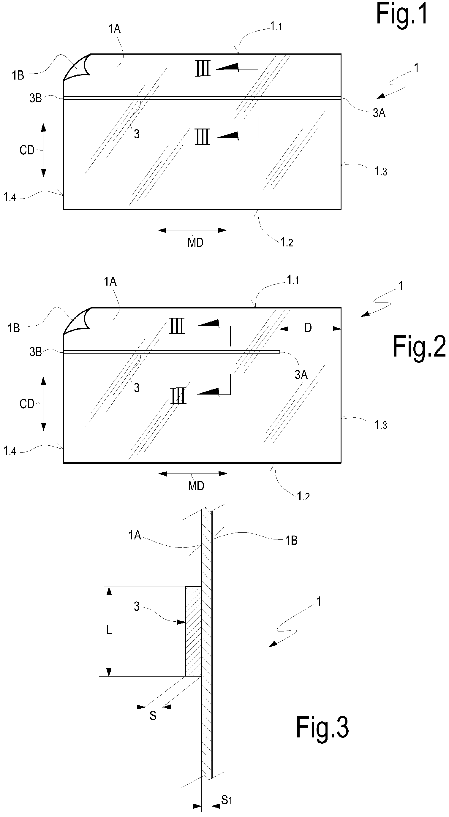
[0011] Figs.1 and 2 show a plastic film usable for making a pack according to the present
disclosure. The film, indicated as a whole with reference number 1, may be made of
polypropylene, polyester, polyethylene and paper.
[0012] The plastic film 1 has a longitudinal dimension MD and a cross dimension CD. Reference
numbers 1.1 and 1.2 designate the two longitudinal edges of the plastic film 1, and
the reference numbers 1.3 and 1.4 designate the two transverse edges of the plastic
film 1. The plastic film 1 may be obtained from a reel of plastic film produced continuously.
The longitudinal direction MD may be the direction parallel to the film winding direction
in the reel, corresponding to the machine direction, along which the film has been
produced during the extrusion process. In this case, the direction CD is the cross
direction, i.e. the direction orthogonal to the machine direction MD.
[0013] The plastic film 1 has a first surface 1A and a second surface 1B. A line-shaped
element 3 is applied to the surface 1A of the plastic film 1, which will face the
inside of the pack. The line-shaped element 3 may be constituted by a strip of polymer
material, for example PVC, polypropylene, polyamide, polyethylene or polyester.
[0014] In some embodiments, the line-shaped element 3 may be arranged so that, in the final
pack, it is on a plane approximately orthogonal to the axes of the rolls contained
in the pack.
[0015] In this context, the term "line-shaped" indicates an element having a longitudinal
dimension substantially larger than the cross dimension, in particular, for example,
by at least two orders of magnitude with respect to the maximum cross dimension. The
maximum cross dimension is, in general, the width, which is in turn by one or more
orders of magnitude larger than the thickness.
[0016] The line-shaped element 3 may be made of a plastic film, i.e. a polymer film. It
can be constituted by a thin and long strip of width comprised between 1 and 3 mm,
for instance. The thickness of the polymer film forming the line-shaped element 3
may be smaller than the width of the strip forming the line-shaped element 3 by approximately
two orders of magnitude. The line-shaped element 3 may have, for example, a thickness
comprised between 15 and 50 micrometers, preferably between 20 and 40 micrometers.
[0017] In the embodiment of Fig. 1, the line-shaped element 3 has a length equal to the
longitudinal dimension of the plastic film 1 and is applied parallel to the longitudinal
edges 1.1 and 1.2 of the plastic film 1.
[0018] In some non claimed embodiments, as shown in Fig. 2, the line-shaped element 3 may
have a length smaller than the longitudinal dimension of the plastic film 1. In the
embodiment of Fig.1 the line-shaped element 3 has a first end 3A and a second end
3B that are arranged respectively at the transverse edges 1.3 and 1.4. Vice versa,
in the embodiment of Fig. 2, only the end 3B of the line-shaped element 3 is at a
transverse edge of the plastic film 1, particularly at the transverse edge 1.4, whilst
the end 3A of the line-shaped element 3 is spaced from the transverse edge 1.3 by
a distance D, for the purposes described below.
[0019] Fig. 3 shows an enlarged cross section of the plastic film 1 according to III-III
of Fig. 1 and Fig. 2. The section is not scaled for the sake of clarity of representation.
Even if not scaled, Fig. 3 shows that the line-shaped element 3 may have a width L
larger than the thickness S. The thickness S of the line-shaped element 3 may be approximately
of the same order of magnitude as the thickness S1 of the plastic film 1.
[0020] The line-shaped element 3 may be applied to the surface 1A of the plastic film 1
by means of gluing, for example with a pressure-sensitive adhesive. In some embodiments,
the line-shaped element 3 may be applied to the surface 1A of the plastic film 1 with
an adhesive based on one or more of the following polymers: acrylic, nitrile, vinyl-ether,
EVA, SBS, SEBS, SIP, SIS, butyl rubber, natural rubber, silicone rubber.
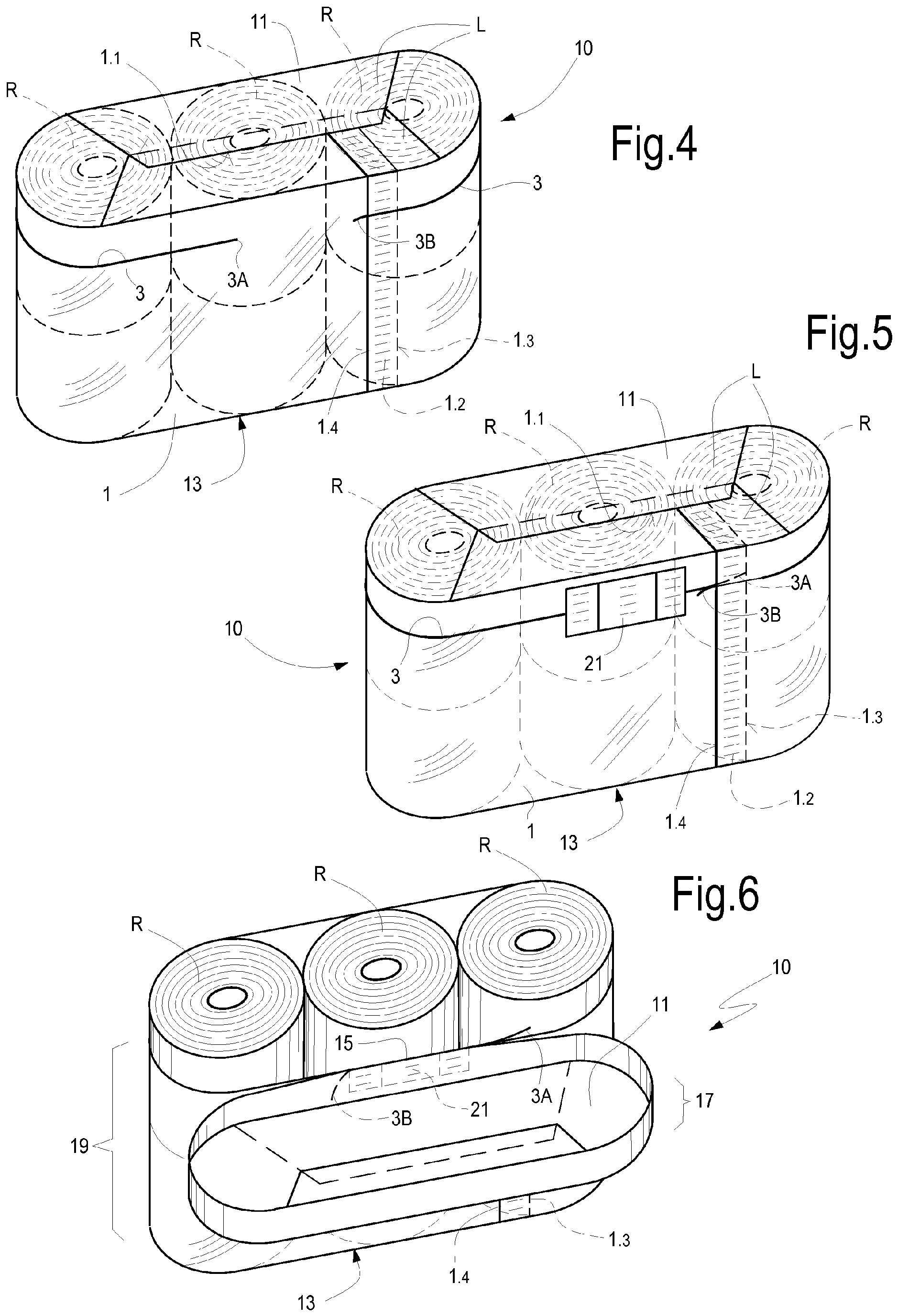
[0021] In the configuration of Fig. 1 or in that of Fig. 2, the plastic film 1 may be used
to form a pack of tissue paper rolls, as shown in Fig. 4. In this figure, the plastic
film 1 of Fig. 2 is used, wherein the line-shaped element 3 has a length smaller than
the longitudinal dimension of the plastic film 1.
[0022] In this embodiment, the pack, labeled 10 as a whole, contains an arrangement of six
tissue paper rolls R arranged on three rows, each of which comprises two rolls. It
will be clearly apparent to those skilled in the art that the number and arrangement
of the rolls may vary also significantly with respect to what illustrated in Fig.
4 just by way of non-limiting example. The pack 10 may comprise, for instance, two
or three overlying layers of rolls, each of which is formed by a matrix arrangement,
for example 2x3=6 rolls.
[0023] The plastic film 1 is wrapped around the ordered group of rolls R so as to wrap the
side surface of the pack, surrounding the rolls cylindrical surfaces. The cross dimension
of the plastic film 1 is such that it projects at two sides with respect to the flat
surfaces of the rolls R. The two portions of plastic film 1 projecting with respect
to the bases of the rolls R form edges L, which are folded and sealed onto the two
approximately flat opposite surfaces 11, 13 of the pack.
[0024] The transverse edges 1.3, 1.4 of the plastic film 1 are arranged on the side surface
of the pack and extend from one approximately flat surface of the pack to the other.
In the illustrated example, the transverse edge 1.4 of the plastic film 1 is outside
the pack, whilst the transverse edge 1.3 is inside the pack. A welding line closing
the pack 10 is provided between the two transverse edges 1.4 and 1.3. The welding
line, schematically indicated with 12, preferably extends parallel to the transverse
edges 1.4 and 1.3 and is spaced from the outer transverse edge 1.4 for example by
a distance comprised between 5 mm and 30 mm. The outer transverse edge 1.4 can be
therefore easily gripped by the user to open the pack as described below.
[0025] The folded edges of the plastic film 1 are welded in order to close the pack in the
area of the longitudinal edges 1.1 e 1.2. The pack can also be closed by means of
gluing.
[0026] The end 3A of the line-shaped element 3 is arranged inside the pack 10, while the
end 3B is arranged on the transverse edge 1.4 of the plastic film 1 and can be accessed
from the outside.
[0027] In order to easily open the pack 10, the user can grip the end 3B of the line-shaped
element 3 and pull it, moving it away from the pack 10. As the welding line 12 has
been made at a certain distance from the transverse edge 1.4, the end 3B of the line-shaped
element 3 can be gripped more easily by the user.
[0028] By pulling the line-shaped element 3 towards the outside, the plastic film 1 tears
along the line-shaped element 3.
[0029] Fig. 6 shows the pack 10 in open arrangement, after the plastic film 1 has been torn
through the action of the line-shaped element 3. Thanks to the fact that the end 3A
of the line-shaped element 3 is provided in intermediate position with respect to
the longitudinal extension of the plastic film 1, at a distance D from the transverse
edge 1.3 (Fig. 2), not the whole plastic film 1 is broken along the line defined by
the line-shaped element 3; namely a portion thereof, indicated with number 15 in Fig.
6, remains undamaged. In this way, the upper part 17 of the pack formed by the plastic
film 1, above the line-shaped element 3, may be lifted, thus freeing the upper layer
of rolls R. However, thanks to the undamaged portion 15 of plastic film 1, the upper
part 17 of the pack 10 remains fastened to the remaining part, indicated with 19,
of the plastic film 1 wrapped around the pack 10. The rolls arranged below the line-shaped
element 3 remain wrapped in the part 19 of the pack 10.
[0030] In this way it is possible, for example, to remove one roll R and to close, at least
partially, the pack using the portion 17 of the plastic film 1 like a cover hinged
to the lower part 19 of the pack 10 at the portion 15
[0031] In order to prevent the plastic film 1 from being torn beyond the end 3A of the line-shaped
element 3, a device or member is applied to the plastic film 1 to avoid tearing thereof,
for example an adhesive label, that can also serve as advertisement, decoration or
mark for the packed product.
[0032] In particular in the case of the invention where the line-shaped element 3 has a
longitudinal extension equal to the longitudinal dimension of the edges 1.1 and 1.2,
as shown in Fig. 1, it is possible to have a similar effect by using a member for
avoiding the breakage or tearing of the plastic film 1. This member may be for example
a self-adhesive label, indicated with 21 in Fig. 5. Pulling the line-shaped element
3 starting from the end 3B accessible from the outside of the pack 10 along the transverse
edge 1.3 results in the film 1 being torn up to the area where the label 21 is provided.
The label 21 avoids any subsequent tearing.
[0033] Having described the general features of the pack, now preferred features of some
embodiments will be described below.
[0034] In various embodiments of the pack, the line-shaped element may be provided with
an adhesive characterized by an adhesion to steel equal to, or lower than, 400 g/25
mm measured according to the FINAT FTM1 standard.
[0035] In some embodiments, the line-shaped element is arranged along a plane orthogonal
to the axes of the rolls R of the pack, the plane being spaced from one of the approximately
flat opposite surfaces by a distance equal to, or lower than 40%, and preferably equal
to, or lower than 30%, and more preferably equal to, or lower than 25% of the overall
distance between the two approximately flat opposite surfaces.
[0036] In possible embodiments, the plastic film 1 may have a thickness comprised between
15 and 50 micrometers, preferably between 20 and 40 micrometers. In order to enhance
the features of the pack, the plastic film 1 may have an anisotropic tensile strength
at break with different values in the direction parallel to the line-shaped element
3 and in the direction orthogonal to the line-shaped element 3.
[0037] The plastic film 1 may have a tensile strength at break in the direction parallel
to the line-shaped element 3 lower than the tensile strength at break in the direction
orthogonal to the line-shaped element 3. In some embodiments, the plastic film 1 may
have an elongation at break in the direction parallel to the line-shaped element 3
greater than the elongation at break in the direction orthogonal to the line-shaped
element 3.
[0038] For example, the plastic film 1 may have a first tensile strength at break in the
direction parallel to the line-shaped element 3 and a second tensile strength at break
in the direction orthogonal to the line-shaped element 3. The ratio between the first
tensile strength at break and the second tensile strength at break can be comprised
between 1:1 and 1:2.5, and preferably between 1:1.05 and 1:2.3, the break strength
being measured according to the ASTM D 882 standard.
[0039] Moreover, in possible embodiments, the plastic film 1 may have a first elongation
at break in the direction orthogonal to the line-shaped element 3 and a second elongation
at break in the direction parallel to the line-shaped element 3. The ratio between
the first elongation at break and the second elongation at break may be comprised
between 1:2 and 1:5.
[0040] The line-shaped element 3 may have a longitudinal elongation at break equal to, or
lower than, 50%, preferably equal to, or lower than, 40%, and more preferably equal
to, or lower than, 30%. The longitudinal tensile strength at break of the line-shaped
element 3 is preferably greater than the longitudinal tensile strength at break of
the plastic film 1. For instance, the longitudinal tensile strength at break of the
line-shaped element 3 can be preferably at least three times the longitudinal tensile
strength at break of the plastic film 1.
[0041] In advantageous exemplary embodiments, the tensile strength at break of the line-shaped
element 3 is equal to, or greater than, 20 kg/25 mm according to the AFERA 4004 standard.
1. A pack of tissue paper rolls, comprising a plurality of rolls (R) of tissue paper
that are arranged adjacent to one another with the respective axes parallel to, or
coinciding with, one another, and are wrapped in a plastic film (1); the plastic film
laterally wraps the rolls and is arranged with a first (1.1) and a second (1.2) longitudinal
edge folded and closed onto two approximately flat opposite surfaces, (11, 13) which
are defined by bases of the tissue paper rolls; wherein the plastic film comprises
a first transverse edge (1.3) and a second transverse edge (1.4) extending from one
flat surface (11) to the other (13), one (1.4) of said first transverse edge and second
transverse edge being outside the pack and the other transverse edge (1.3) being inside
the pack; characterised in that a line-shaped element (3) having a first end (3A) and a second end (3B) is applied
to a surface of the plastic film; wherein at least one (3B) of said first end and
second end of the line-shaped element is arranged near, or at the transverse edge
(1.4) of the plastic film outside the pack; and wherein the line-shaped element (3)
completely surrounds the pack and wherein a member (21) is applied to the plastic
film to prevent the plastic film from breaking, said member being applied along the
line-shaped element (3).
2. Pack according to claim 1, wherein the line-shaped element (3) is applied to the surface
of the plastic film (1) facing the inside of the pack.
3. Pack according to claim 1 or 2, wherein the line-shaped element (3) is constituted
by a strip of polymer material.
4. Pack according to one or more of the previous claims, wherein the line-shaped element
(3) is applied by means of gluing to the plastic film (1); and wherein preferably
the line-shaped element has an adhesive characterized by an adhesion to steel equal to, or lower than 400 g/25 mm measured according to the
FINAT FTM1 standard.
5. Pack according to one or more of the previous claims, wherein the line-shaped element
(3) is arranged on a plane approximately orthogonal to the axes of the rolls. (R)
6. Pack according to claim 5, wherein the plane where the line-shaped element (3) is
arranged is spaced from one of said approximately flat opposite surfaces (11, 13)
by a distance equal to, or lower than, 40%, preferably equal to, or lower than, 30%,
more preferably equal to, or lower than, 25% of the overall distance between the two
approximately flat opposite surfaces.
7. Pack according to one or more of the previous claims, wherein the thickness of the
plastic film (1) is comprised between 15 and 50 micrometers, preferably between 20
and 40 micrometers.
8. Pack according to one or more of the previous claims, wherein the plastic film (1)
has an anisotropic tensile strength at break, with different values in the direction
parallel to the line-shaped element (3) and in the direction orthogonal to the line-shaped
element (3).
9. Pack according to one or more of the previous claims, wherein the plastic film (1)
has a tensile strength at break in the direction parallel to the line-shaped element
(3) lower than the tensile strength at break in the direction orthogonal to the line-shaped
element (3).
10. Pack according to one or more of the previous claims, wherein the plastic film (1)
has an elongation at break in the direction parallel to the line-shaped element (3)
greater than the elongation at break in the direction orthogonal to the line-shaped
element (3).
11. Pack according to one or more of the previous claims, wherein the plastic film (1)
has a first tensile strength at break in the direction parallel to the line-shaped
element (3) and a second tensile strength at break in the direction orthogonal to
the line-shaped element (3); and wherein the ratio between the first tensile strength
at break and the second tensile strength at break is comprised between 1:1 and 1:2.5
and preferably between 1:1.1 and 1:2.3, the break strength being measured according
to the ASTM D 882 standard.
12. Pack according to one or more of the previous claims, wherein the plastic film (1)
has a first elongation at break in the direction orthogonal to the direction of the
line-shaped element (3) and a second elongation at break in the direction parallel
to the direction of the line-shaped element (3) and wherein the ratio between the
first elongation at break and the second elongation at break is comprised between
1:2 and 1:5.
13. Pack according to one or more of the previous claims, wherein a width of the line-shaped
element (3) is comprised between 1 and 3 mm.
14. Pack according to one or more of the previous claims, wherein a thickness of the line-shaped
element (3) is comprised between 15 and 50 micrometers, preferably between 20 and
40 micrometers.
15. Pack according to one or more of the previous claims, wherein the line-shaped element
(3) has a longitudinal elongation at break equal to, or lower than, 50%, preferably
equal to, or lower than, 40%, and more preferably equal to, or lower than, 30%.
16. Pack according to one or more of the previous claims, wherein the longitudinal tensile
strength at break of the line-shaped element (3) is greater than the longitudinal
tensile strength at break of the plastic film (1); and wherein the longitudinal tensile
strength at break of the line-shaped element (3) is preferably at least three times
the longitudinal tensile strength at break of the plastic film. (1)
17. Pack according to one or more of the previous claims, wherein the tensile strength
at break of the line-shaped element (3) is equal to, or greater than, 20 kg/25 mm
according to the AFERA 4004 standard.
1. Packung von Tissuepapierrollen, umfassend eine Mehrzahl von Rollen (R) von Tissuepapier,
die nebeneinander angeordnet sind, wobei die jeweiligen Achsen parallel zueinander
sind oder zusammenfallen, und in eine Kunststofffolie (1) eingewickelt sind; wobei
die Kunststofffolie die Rollen seitlich umhüllt, und mit einer ersten (1.1) und einer
zweiten (1.2) Längskante auf zwei ungefähr flachen gegenüberliegenden Oberflächen
(11, 13) gefaltet und geschlossen angeordnet ist, die durch Grundflächen der Tissuepapierrollen
definiert sind, wobei die Kunststofffolie eine erste Querkante (1.3) und eine zweite
Querkante (1.4) umfasst, die sich von einer ebenen Oberfläche (11) zur anderen (13)
erstrecken, wobei eine (1.4) von der genannten ersten Querkante und der zweiten Querkante
außerhalb der Packung liegt, und die andere Querkante (1.3) innerhalb der Packung
liegt; dadurch gekennzeichnet, dass ein linienförmiges Element (3) mit einem ersten Ende (3A) und einem zweiten Ende
(3B) auf eine Oberfläche der Kunststofffolie aufgebracht ist; wobei (3B) das erste
Ende und/oder das zweite Ende des linienförmigen Elements in der Nähe oder an der
Querkante (1.4) der Kunststofffolie außerhalb der Packung angeordnet ist/sind; und
wobei das linienförmige Element (3) die Packung vollständig umgibt und wobei ein Element
(21) auf die Kunststofffolie aufgebracht ist, um ein Brechen der Kunststofffolie zu
verhindern, wobei das genannte Element entlang des linienförmigen Elements (3) aufgebracht
ist.
2. Packung nach Anspruch 1, wobei das linienförmige Element (3) auf die Oberfläche der
Kunststofffolie (1) aufgebracht ist, die dem Inneren der Packung zugewandt ist.
3. Packung nach Anspruch 1 oder 2, wobei das linienförmige Element (3) aus einem Streifen
von Polymermaterial besteht.
4. Packung nach einem oder mehreren der vorhergehenden Ansprüche, wobei das linienförmige
Element (3) mittels Kleben auf die Kunststofffolie (1) aufgebracht ist; und wobei
das linienförmige Element vorzugsweise einen Klebstoff aufweist, der durch eine Haftung
an Stahl gleich 400 g/25 mm oder niedriger, gemessen nach dem FINAT FTM1-Standard,
gekennzeichnet ist.
5. Packung nach einem oder mehreren der vorhergehenden Ansprüche, wobei das linienförmige
Element (3) auf einer Ebene angeordnet ist, die ungefähr orthogonal zu den Achsen
der Rollen (R) ist.
6. Packung nach Anspruch 5, wobei die Ebene, worauf das linienförmige Element (3) angeordnet
ist, von einer der genannten, ungefähr flachen gegenüberliegenden Oberflächen (11,
13) um einen Abstand gleich oder niedriger als 40 %, vorzugsweise gleich oder niedriger
als 30 %, bevorzugter gleich oder niedriger als 25 % des Gesamtabstands zwischen den
zwei ungefähr flachen gegenüberliegenden Oberflächen beabstandet ist.
7. Packung nach einem oder mehreren der vorhergehenden Ansprüche, wobei die Dicke des
Kunststofffilms (1) zwischen 15 und 50 Mikrometer, vorzugsweise zwischen 20 und 40
Mikrometer liegt.
8. Packung nach einem oder mehreren der vorhergehenden Ansprüche, wobei die Kunststofffolie
(1) eine anisotrope Bruchzugfestigkeit mit unterschiedlichen Werten in der Richtung
parallel zum linienförmigen Element (3) und in der Richtung orthogonal zum linienförmigen
Element (3) aufweist.
9. Packung nach einem oder mehreren der vorhergehenden Ansprüche, wobei die Kunststofffolie
(1) eine Bruchzugfestigkeit in der Richtung parallel zum linienförmigen Element (3)
aufweist, die niedriger als die Bruchzugfestigkeit in der Richtung orthogonal zum
linienförmigen Element (3) ist.
10. Packung nach einem oder mehreren der vorhergehenden Ansprüche, wobei die Kunststofffolie
(1) eine Bruchdehnung in der Richtung parallel zum linienförmigen Element (3) aufweist,
die größer als die Bruchdehnung in der Richtung orthogonal zum linienförmigen Element
(3) ist.
11. Packung nach einem oder mehreren der vorhergehenden Ansprüche, wobei der Kunststofffilm
(1) eine erste Bruchzugfestigkeit in der Richtung parallel zum linienförmigen Element
(3) und eine zweite Bruchzugfestigkeit in der Richtung orthogonal zum linienförmigen
Element (3) aufweist;
und wobei das Verhältnis zwischen der ersten Bruchzugfestigkeit und der zweiten Bruchzugfestigkeit
zwischen 1:1 und 1:2,5 und vorzugsweise zwischen 1:1,1 und 1:2,3 liegt, wobei die
Bruchfestigkeit nach der Norm ASTM D 882 gemessen wird.
12. Packung nach einem oder mehreren der vorhergehenden Ansprüche, wobei die Kunststofffolie
(1) eine erste Bruchdehnung in der Richtung orthogonal zur Richtung des linienförmigen
Elements (3) und eine zweite Bruchdehnung in der Richtung parallel zur Richtung des
linienförmigen Elements (3) aufweist, und wobei das Verhältnis zwischen der ersten
Bruchdehnung und der zweiten Bruchdehnung zwischen 1:2 und 1:5 liegt.
13. Packung nach einem oder mehreren der vorhergehenden Ansprüche, wobei eine Breite des
linienförmigen Elements (3) zwischen 1 und 3 mm liegt.
14. Packung nach einem oder mehreren der vorhergehenden Ansprüche, wobei eine Dicke des
linienförmigen Elements (3) zwischen 15 und 50 Mikrometer, vorzugsweise zwischen 20
und 40 Mikrometer liegt.
15. Packung nach einem oder mehreren der vorhergehenden Ansprüche, wobei das linienförmige
Element (3) eine Längsbruchdehnung gleich oder niedriger als 50 %, vorzugsweise gleich
oder niedriger als 40 % und bevorzugter gleich oder niedriger als 30 % aufweist.
16. Packung nach einem oder mehreren der vorhergehenden Ansprüche, wobei die Längsbruchzugfestigkeit
des linienförmigen Elements (3) größer als die Längsbruchzugfestigkeit der Kunststofffolie
(1) ist; und wobei die Längsbruchzugfestigkeit des linienförmigen Elements (3) vorzugsweise
mindestens das Dreifache der Längsbruchzugfestigkeit der Kunststofffolie (1) beträgt.
17. Packung nach einem oder mehreren der vorhergehenden Ansprüche, wobei die Bruchzugfestigkeit
des linienförmigen Elements (3) gleich oder größer als 20 kg/25 mm gemäß der Norm
AFERA 4004 ist.
1. Paquet de rouleaux de papier toilette, comprenant une pluralité de rouleaux (R) de
papier toilette qui sont disposés de manière adjacente les uns aux autres avec les
axes respectifs parallèles les uns aux autres, ou coïncidant les uns avec les autres,
et qui sont enveloppés dans un film plastique (1); le film plastique enveloppe latéralement
les rouleaux et est disposé avec un premier (1.1) et un deuxième (1.2) bord longitudinal
plié et fermé sur deux surfaces opposées (11, 13), approximativement planes qui sont
définies par des bases des rouleaux de papier toilette, dans lequel le film plastique
comprend un premier bord transversal (1.3) et un deuxième bord transversal (1.4) s'étendant
d'une surface plane (11) à l'autre (13), l'un (1.4) desdits premier bord transversal
et deuxième bord transversal étant à l'extérieur du paquet et l'autre bord transversal
(1.3) étant à l'intérieur du paquet; caractérisé en ce qu'un élément (3) en forme de ligne ayant une première extrémité (3A) et une deuxième
extrémité (3B) est appliqué à une surface du film plastique ; dans lequel au moins
une (3B) desdites première extrémité et deuxième extrémité de l'élément en forme de
ligne est disposée au bord transversal (1.4) du film plastique, ou à proximité, à
l'extérieur du paquet ; et dans lequel l'élément (3) en forme de ligne entoure entièrement
le paquet et dans lequel un membre (21) est appliqué au film plastique pour éviter
que le film plastique ne se rompe, le membre étant appliqué le long de l'élément (3)
en forme de ligne.
2. Paquet selon la revendication 1, dans lequel l'élément (3) en forme de ligne est appliqué
à la surface du film plastique (1) faisant face à l'intérieur du paquet.
3. Paquet selon la revendication 1 ou 2, dans lequel l'élément (3) en forme de ligne
est constitué par une bande de matériau polymère.
4. Paquet selon une ou plusieurs des revendications précédentes, dans lequel l'élément
(3) en forme de ligne est appliqué par moyen de collage au film plastique (1) et dans
lequel, de préférence, l'élément en forme de ligne a une caractéristique d'adhésion,
par adhésion à l'acier, égale ou inférieure à 400g/25mm, mesurée selon le standard
FINAT FTM1.
5. Paquet selon une ou plusieurs des revendications précédentes, dans lequel l'élément
(3) en forme de ligne est disposé sur un plan approximativement orthogonal aux axes
des rouleaux (R).
6. Paquet selon la revendication 5, dans lequel le plan où l'élément (3) en forme de
ligne est disposé et espacé de l'une desdites surface opposées approximativement planes
(11, 13) d'une distance égale à ou inférieure à 40%, préférentiellement égale à ou
inférieure à 30%, et encore préférentiellement égale à ou inférieure à 25% de la distance
globale entre les deux surfaces opposées approximativement plates.
7. Paquet selon une ou plusieurs des revendications précédentes, dans lequel l'épaisseur
du film plastique (1) est comprise entre 15 et 50 micromètres, de préférence entre
20 et 40 micromètres.
8. Paquet selon une ou plusieurs des revendications précédentes, dans lequel le film
plastique (1) a une résistance à la rupture en tension anisotrope avec des valeurs
différentes dans la direction parallèle à l'élément (3) en forme de ligne et dans
la direction orthogonale à l'élément (3) en forme de ligne.
9. Paquet selon une ou plusieurs des revendications précédentes, dans lequel le film
plastique (1) a une résistance à la rupture en tension dans la direction parallèle
à l'élément (3) en forme de ligne plus faible que la résistance à la rupture en tension
dans la direction orthogonale à l'élément (3) en forme de ligne.
10. Paquet selon une ou plusieurs des revendications précédentes, dans lequel le film
plastique (1) présente un allongement à la rupture dans la direction parallèle à l'élément
(3) en forme de ligne plus grand que l'allongement à la rupture dans la direction
orthogonale à l'élément (3) en forme de ligne.
11. Paquet selon une ou plusieurs des revendications précédentes, dans lequel le film
plastique (1) a une première résistance à la rupture en tension dans la direction
parallèle à l'élément (3) en forme de ligne et une deuxième résistance à la rupture
en tension dans la direction orthogonale à l'élément (3) en forme de ligne, et dans
lequel le rapport entre la première résistance à la rupture en tension et la deuxième
résistance à la rupture en tension est compris entre 1:1 et 1:2.5 et de préférence
entre 1:1.1 et 1:2.3, la résistance à la rupture étant mesurée selon le standard ASTM
D 882.
12. Paquet selon une ou plusieurs des revendications précédentes, dans lequel le film
plastique (1) présente un premier allongement à la rupture dans la direction orthogonale
à la direction de l'élément (3) en forme de ligne, et une deuxième élongation à la
rupture dans la direction parallèle à l'élément (3) en forme de ligne, et dans lequel
le rapport entre la première élongation à la rupture et la deuxième élongation à la
rupture est comprise entre 1:2 et 1:5.
13. Paquet selon une ou plusieurs des revendications précédentes, dans lequel une largeur
de l'élément (3) en forme de ligne est comprise entre 1 et 3 mm.
14. Paquet selon une ou plusieurs des revendications précédentes dans lequel une épaisseur
de l'élément (3) en forme de ligne est comprise entre 15 et 50 micromètres, de préférence
entre 20 et 40 micromètres.
15. Paquet selon une ou plusieurs des revendications précédentes, dans lequel l'élément
(3) en forme de ligne présente un allongement à la rupture longitudinal égal ou inférieur
à 50%, de préférence égal ou inférieur à 40% et encore de préférence égal ou inférieur
à 30%.
16. Paquet selon une ou plusieurs des revendications précédentes, dans lequel la résistance
à la rupture en tension longitudinale de l'élément (3) en forme de ligne est supérieure
à la résistance à la rupture en tension longitudinale du film plastique (1) et dans
lequel la résistance à la rupture en tension longitudinale de l'élément (3) en forme
de ligne est de préférence d'au moins trois fois la résistance à la rupture en tension
longitudinale du film plastique (1).
17. Paquet selon une ou plusieurs des revendications précédentes, dans lequel la résistance
à la rupture en tension de l'élément (3) en forme de ligne est supérieure ou égale
à 20kg/25mm selon le standard AFERA 4004.
REFERENCES CITED IN THE DESCRIPTION
This list of references cited by the applicant is for the reader's convenience only.
It does not form part of the European patent document. Even though great care has
been taken in compiling the references, errors or omissions cannot be excluded and
the EPO disclaims all liability in this regard.
Patent documents cited in the description