| (19) |
 |
|
(11) |
EP 3 450 896 B1 |
| (12) |
EUROPEAN PATENT SPECIFICATION |
| (45) |
Mention of the grant of the patent: |
|
13.01.2021 Bulletin 2021/02 |
| (22) |
Date of filing: 25.01.2017 |
|
| (51) |
International Patent Classification (IPC):
|
| (86) |
International application number: |
|
PCT/EA2017/000001 |
| (87) |
International publication number: |
|
WO 2017/186253 (02.11.2017 Gazette 2017/44) |
|
| (54) |
PYROLYSIS FURNACE WITH EXTERNAL HEATING FOR PROCESSING SOLID CARBON-CONTAINING MATERIALS
(VARIANTS)
PYROLYSEOFEN MIT EXTERNER ERWÄRMUNG ZUR VERARBEITUNG VON FESTEN KOHLENSTOFFHALTIGEN
MATERIALIEN (VARIANTEN)
FOUR À PYROLYSE À CHAUFFAGE EXTERNE POUR LA TRANSFORMATION DE MATÉRIAUX SOLIDES CONTENANT
DES HYDROCARBURES (VARIANTES)
|
| (84) |
Designated Contracting States: |
|
AL AT BE BG CH CY CZ DE DK EE ES FI FR GB GR HR HU IE IS IT LI LT LU LV MC MK MT NL
NO PL PT RO RS SE SI SK SM TR |
| (30) |
Priority: |
26.04.2016 EA 2016003
|
| (43) |
Date of publication of application: |
|
06.03.2019 Bulletin 2019/10 |
| (73) |
Proprietor: ThermoDeg s.r.o. |
|
929 01 Dunajská Streda (SK) |
|
| (72) |
Inventor: |
|
- ZHDANOK, Vitali Aleksandrovich
Minsk (BY)
|
| (74) |
Representative: Danubia Patent & Law Office LLC |
|
Bajcsy-Zsilinszky út 16
1051 Budapest
1051 Budapest (HU) |
| (56) |
References cited: :
CN-A- 105 385 459
CN-U- 204 848 280
RU-C1- 2 146 790
RU-C1- 2 555 892
RU-C2- 2 478 573
|
CN-U- 204 324 899
RU-A- 2010 102 105
RU-C1- 2 418 246
RU-C2- 2 478 573
US-A1- 2015 362 183
|
|
| |
|
|
|
|
| |
|
| Note: Within nine months from the publication of the mention of the grant of the European
patent, any person may give notice to the European Patent Office of opposition to
the European patent
granted. Notice of opposition shall be filed in a written reasoned statement. It shall
not be deemed to
have been filed until the opposition fee has been paid. (Art. 99(1) European Patent
Convention).
|
[0001] The invention relates to power generation and the environment and is intended for
the thermal processing of solid and free-flowing materials, in particular in processes
for the pyrolysis of solid carbon-containing materials, including municipal and domestic
waste. The apparatus can also be used for activation of carbon materials, calcination,
drying and in other operational procedures associated with heating in a controlled
environment.
[0002] A method of thermal decomposition of fuels [1] is known in the prior art, in which
furnace walls are made of flameless gas burners. Fuel enters the upper part of the
furnace and, while descending, is directly exposed to infrared rays, which enables
intensification of the process. The disadvantage of the method is that radiant heat
cannot be transferred to the entire depth of the product layer.
[0003] Another prior art discloses an assembly for thermal decomposition of carbon-containing
materials [2]. The assembly comprises a rotating drum with a retort installed axisymmetrically
therein; pyrolysis gases are burned in an annular space between the retort and walls
of the drum, whereby external radiating/conductive heating of the retort is provided.
[0004] The disadvantage of the known invention is the uneven heating of the retort and the
drum.
[0005] The prior art most closely related to the present invention by its technical nature
is an externally heated pyrolysis furnace for carbonization and activation of carbon
material [3], comprising a hollow rotating body having an inlet and a discharging
side and mounted with a downward tilt towards the discharging side; a housing surrounding
the body and defining, together with the body, a plurality of heating chambers; gas
burners in each heating chamber, wherein the temperature of each chamber is independently
adjustable; annular partitions spaced apart along the rotating body to control the
movement of material through the body; means for supplying carbonaceous material to
the charging end; a feed pipe for supplying substantially oxygen-free vapour or carbon
dioxide into the rotating body.
[0006] The pyrolysis furnace is insufficiently reliable and safe due to the use of flame
gas burners and the potential for overheating the rotating body at elevated temperature
of the gas burner torch, as well as the insufficient intensity of heat exchange and
a certain complexity of maintenance.
[0007] The object of the present invention is to provide an externally heated drum-type
pyrolysis furnace for processing solid carbon-containing materials, which exhibits
enhanced reliability, safety, heat transfer efficiency and improved maintainability.
[0008] The object is attained in an externally heated pyrolysis furnace for processing solid
carbon-containing materials, comprising a base 1; a pyrolysis chamber 2 disposed on
said base and being in the shape of a cylinder with end covers 3, which are connected
to a charging tube 4 and a discharging tube 5; a heating chamber 6, which surrounds
the pyrolysis chamber 2 and includes a thermally-insulated housing 7 having disposed
therein heating elements 8 and 9, partitions 10, 11, 12 and a branch pipe 13 for the
removal of flue gases, which is situated in the upper part of the heating chamber
6; a feed pipe 14 for supplying an atmosphere of water vapour or carbon dioxide to
the pyrolysis chamber 2; and a pipe 15 for the removal of gaseous products from the
pyrolysis chamber 2. The heating chamber 6 is assembled from an upper part and a lower
part, which can be joined; each of the parts of the heating chamber 6 is provided
with two rows of heating elements 8, 9, which are arranged along the length of the
housing 7 of the heating chamber 6 symmetrically relative to a vertical plane which
passes through the axis of the pyrolysis chamber 2. The heating elements 8, 9 are
in the form of units containing at least one flameless gas burner, wherein the heating
elements 8 in the upper part of the heating chamber 6 are arranged in a checkerboard
fashion relative to the heating elements 9 in the lower part of the heating chamber
6. The partitions 10, 11, 12 comprise: two end annular partitions 10 disposed on the
edges of the heating chamber 6; a partition 11 disposed along the lower part of the
heating chamber 6; annular partitions 12 defining pairwise separate gas channels 16
for each heating element 8, 9 for exhaust gas streams leaving them. The branch pipe
13 for the removal of flue gases is provided with a heat exchanger 17, to which the
feed pipe 14 is connected for supplying an atmosphere of water vapour or carbon dioxide
to the pyrolysis chamber 2.
[0009] Alternatively to the first embodiment, in the second embodiment the partitions comprise:
two end annular partitions 10 disposed on the edges of the heating chamber 6; a partition
11 disposed along the lower part of the heating chamber 6; screening partitions 18
in the upper part of the heating chamber 6 for directing the exhaust gas stream from
the heating element 8 upward the heating chamber 6 and restricting the influence of
the heating elements 9 of the lower part of the heating chamber 6 on them; and screening
partitions 19 in the lower part of the heating chamber 6 for restricting lateral movement
of the exhaust gas stream from the heating elements 9 and the mutual influence thereof.
[0010] Furthermore, in the preferred second embodiment the screening partitions 18 consist
of two side parts made in the form of a ring segment and disposed on both sides of
each heating element 8, the side parts being coupled by a splitter directed toward
the heating elements 9. The screening partitions 19 also made in the form of a ring
segment.
[0011] In both embodiments the pyrolysis chamber 2 can be a drum-type or screw-type chamber.
[0012] In both embodiments the heat exchanger 17 is preferably coil-shaped, and the pyrolysis
chamber 2 is provided with pressure and temperature sensors.
[0013] Use of the present invention offers the following technical advantages.
- 1. The use of flameless gas burners as heating elements eliminates potential overheating
of the pyrolysis chamber walls when gas is burned in them owing to the absence of
open flame and exposure of the walls to high temperature effects, whereby reliability
and safety are enhanced.
- 2. The arrangement of heating elements in a checkerboard fashion provides even distribution
of radiation fluxes and exhaust gas streams from the heating elements over the outer
surface of the pyrolysis chamber, and the present options of arrangement of partitions
in the heating chamber housing can organize movement of flue gases from operating
heating elements such that they would not influence each other and impair their performance,
and the high-temperature combustion products (flue gases) would not go beyond the
heating chamber through its end surfaces, while evenly flowing around the pyrolysis
chamber surface with maximum contact area. Such an optimal combination of radiant
heating (by radiation) and convective heating (by contact with flue gases) of the
pyrolysis chamber in the present heating chamber design significantly intensifies
the heat exchange between the heating chamber and the pyrolysis chamber compared to
heating only by flue gases when flame gas burners are used.
- 3. The assembly of the heating chamber from upper and lower parts, which can be joined,
enhances maintainability owing to the fact that maintenance and replacement of the
pyrolysis chamber can be organized with the upper part of the heating chamber removed.
[0014] The invention is illustrated in the drawings.
Fig. 1 is a general view of an externally heated pyrolysis furnace.
Fig. 2 is a cross sectional view of an externally heated pyrolysis furnace (section
A-A, right side view).
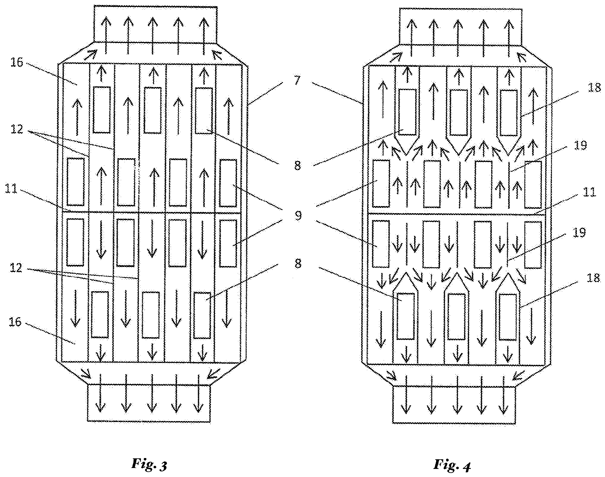
Fig. 3 is a developed view of a fragment of the heating chamber, first embodiment.
Fig. 4 is a developed view of a fragment of the heating chamber, second embodiment.
[0015] An externally heated pyrolysis furnace for processing solid carbon-containing materials
(Fig. 1, 2) comprises a base 1, in particular, a support frame, on which a pyrolysis
chamber 2 is disposed on two support racks, the pyrolysis chamber having the shape
of a cylinder with end covers 3 connected with a charging tube 4 and a discharging
tube 5; a heating chamber 6 surrounding the pyrolysis chamber 2 and including a thermally-insulated
housing 7 with heating elements 8, 9 disposed thereon. A branch pipe 13 for the removal
of flue gases is arranged in the upper part of the heating chamber 6 along its entire
length and is provided with a heat exchanger 17, preferably coil-shaped, to which
a feed pipe 14 is connected for supplying the atmosphere of water vapour or carbon
dioxide into the pyrolysis chamber 2. The pyrolysis furnace further comprises a pipe
15 for the removal of gaseous products from the pyrolysis chamber 2. The heating chamber
6 is assembled from an upper part and a lower part, which can be joined; the upper
part of the heating chamber 6 is provided with two rows of heating elements 8, and
the lower part of the heating chamber 6 is provided with two rows of heating elements
9. The heating elements 8, 9 are arranged along the length of the housing 7 of the
heating chamber 6 symmetrically relative to a vertical plane which passes through
the axis of the pyrolysis chamber 2. The heating elements 8, 9 are made in the form
of units, each unit may consist of one or more burners to reach a specified power
of the unit and/or to provide a radiating surface with a specified shape and area.
The heating elements 8 in the upper part of the heating chamber 6 are arranged in
a checkerboard fashion relative to the heating elements 9 in the lower part of the
heating chamber 6.
[0016] The invention is presented in two embodiments. According to a first embodiment, the
partitions comprise: two end annular partitions 10 (Fig. 2) disposed on the edges
of the heating chamber 6 and restricting exhaust of flue gases from the heating elements
8, 9 outward from the heating chamber 6 through its end surfaces; a partition 11 (Figs.
2, 3, 4) disposed along the lower side of the heating chamber 6 and dividing the inner
space of the heating chamber 6 into two parts to form thereby two symmetrical ascending
exhaust gas streams from the heating elements 8, 9, which flow around the pyrolysis
chamber 2 from opposite sides; annular partitions 12 (Fig. 3) defining pairwise separate
gas channels 16 for each heating element 8, 9 for flue gases exhaust from them.
[0017] The second embodiment also comprises two end annular partitions 10 (Fig.2) disposed
at ends of the heating chamber 6; a partition 11 (Figs. 2, 3, 4) disposed along the
lower part of the heating chamber 6 and dividing the internal space of the heating
chamber 6 into two parts to form thereby two symmetrical ascending exhaust gas streams
from the heating elements 8, 9, which flow around the pyrolysis chamber 2 from opposite
sides. In contract to the first embodiment, the second embodiment comprises screening
partitions 18, 19 {Fig. 4). The screening partitions 18 in the upper part of the heating
chamber 6, which direct the exhaust gas stream from the heating elements 8 upward
the heating chamber 6 and restrict the influence on them of the heating elements 9
of the lower part of the heating chamber 6, in the preferred embodiment are made from
two side parts in the form of a ring segment, which are disposed on both sides of
each heating element 8 and are connected by a splitter directed towards the heating
elements 9. The screening partitions 19 in the lower part of the heating chamber 6,
which restrict lateral movement of flue gases exhaust from the heating elements 9
and their mutual influence on each other, are also made in the form of a ring segment
in this example.
[0018] In both embodiments the pyrolysis chamber 2 can be a drum-type or screw-type chamber.
[0019] If a drum-type pyrolysis chamber 2 is used, the end covers 3 are provided with end
seals (not shown) to ensure immobility of the covers 3 when the drum-type pyrolysis
chamber 2 is rotating.
[0020] The pyrolysis chamber 2 can be provided with pressure and temperature sensors (not
shown).
[0021] The externally heated pyrolysis furnace according to the invention can use an automation
system.
[0022] The externally heated pyrolysis furnace according to the first embodiment operates
as follows.
[0023] Carbon dioxide is fed, via the feed pipe 14, into the pyrolysis chamber 2, and the
pyrolysis chamber 2 is purged to displace residual air. Combustion gas is then supplied
to the heating elements 9 and they are ignited. The pyrolysis chamber 2 is exposed
to thermal radiation from the heating elements 9, and owing to convection the heat
of flue gases resulting from operation of the heating elements, which, being pushed
away from the partition 11 dividing the internal space of the heating chamber 6 into
two symmetrical parts, move upward through the gas channels 16 defined by the annular
partitions 12 and outward from the heating chamber 6 through the branch pipe 13, while
flowing around the outer surface of the pyrolysis chamber 2 from both sides relative
to the vertical plane in which the partition 11 is disposed. Combustion gas is fed
to the heating elements 8 and they are ignited. The intensity of heating the pyrolysis
chamber 2 increases due to the additional effect of thermal radiation from the heating
elements 8 and also due to convective heat transfer from the flue gases resulting
from operation of the heating elements; these flue gases are carried away by the exhaust
gas streams from the heating elements 9, move upward and outward from the heating
chamber 6 via the branch pipe 13; therewith, the uniformity of heating the surface
of the pyrolysis chamber 2 is improved due to the checkerboard arrangement of the
heating elements 8 and 9. Flue gases resulting from the operation of the heating elements
8 and 9 leave the heating chamber 6 through the branch pipe 13, while flowing around
the heat exchanger 17 and heating the same by convention. Water vapour or carbon dioxide,
heated in the heat exchanger 17, is supplied through the feed pipe 14 into the pyrolysis
chamber 2 to provide protective atmosphere therein. Pre-ground solid carbon-containing
material is supplied via the charging tube 4 into the heated pyrolysis chamber 2,
where it contacts the inner surface of the pyrolysis chamber 2, having high temperature
owing to the heat transfer from the heating elements 8 and 9 and flue gases exhaust
from them, and the pyrolysis process takes place. Pyrolysis gas entering the pipe
15 is withdrawn outward from the pyrolysis chamber 2; solid residue resulting from
the decomposition of the solid carbon-containing material after release of pyrolysis
gas is also withdrawn outward from the pyrolysis chamber 2 through the discharging
tube 5.
[0024] Operation of the externally heated pyrolysis furnace according to the second embodiment
is different from that according to the first embodiment in that the flue gases resulting
from operation of the heating elements 9, pushed away from the partition 11, move
upward the heating chamber 6, while the screening partitions 19 restrict lateral movement
of the exhaust gas streams from adjacent heating elements 9 and mutual influence of
the heating elements 9. Then the exhaust gas flows around the outer surface of the
pyrolysis chamber 2 from both sides relative to the vertical plane, in which the partition
11 is disposed, flows around outer sides of the screening partitions 18 and leave
the heating clamber 6 via the branch pipe 13, while flowing around the heat exchanger
17 and heating the same by convention.
[0025] Flue gases resulting from operation of the heating elements 8, pushed away from the
screening partitions 18, move upward the heating chamber 6, mix with the exhaust gas
stream from the heating elements 9 and leave the heating chamber 6 via the branch
pipe 13, while flowing around the heat exchanger 17 and also heating the same by convention.
Therewith, the partitions 18 cut the flue gases resulting from operation of the heating
elements 9 and rising up to the output branch pipe 13 and do not adversely affect
ignition and performance of the heating elements 9.
[0026] References cited:
- 1. Inv. Cert. SU 167812, C10B, publ. 05.11.1965
- 2. Inv. Cert. SU 397729, F27B 7/04, publ. 1970.
- 3. Patent RU 2478573, C01B31/08, C10B47/30, C10B53/07, F27B 7/16, publ. 10.04.2013
1. An externally heated pyrolysis furnace for processing solid carbon-containing materials,
comprising a base 1; a pyrolysis chamber 2 disposed on said base and being in the
shape of a cylinder with end covers 3, which are connected to a charging tube 4 and
a discharging tube 5; a heating chamber 6, which surrounds the pyrolysis chamber 2
and includes a thermally-insulated housing 7 having disposed therein heating elements
8 and 9, partitions 10, 11, 12 and a branch pipe 13 for the removal of flue gases,
which is situated in the upper part of the heating chamber 6; a feed pipe 14 for supplying
an atmosphere of water vapour or carbon dioxide gas to the pyrolysis chamber 2; and
a pipe 15 for the removal of gaseous products from the pyrolysis chamber 2, characterized in that the heating chamber 6 is assembled from an upper part and a lower part, which can
be joined; each of the parts of the heating chamber 6 is provided with two rows of
heating elements 8, 9, which are arranged along the length of the housing 7 of the
heating chamber 6 symmetrically relative to a vertical plane passing through the axis
of the pyrolysis chamber 2; the heating elements 8, 9 are in the form of units containing
at least one flameless gas burner, wherein the heating elements 8 in the upper part
of the heating chamber 6 are arranged in a checkerboard fashion relative to the heating
elements 9 in the lower part of the heating chamber 6; the partitions 10, 11, 12 comprise:
two end annular partitions 10 disposed on the edges of the heating chamber 6; a partition
11 disposed along the lower part of the heating chamber 6; annular partitions 12 defining
pairwise separate gas channels 16 for each heating element 8, 9 for exhaust gas streams
leaving them; the branch pipe 13 for the removal of flue gases is provided with a
heat exchanger 17, to which the feed pipe 14 is connected for supplying an atmosphere
of water vapour or carbon dioxide to the pyrolysis chamber 2.
2. The furnace according to claim 1, characterized in that the pyrolysis chamber 2 is a drum-type chamber.
3. The furnace according to claim 1, characterized in that pyrolysis chamber 2 is a screw-type chamber.
4. The furnace according to 1, characterized in that heat exchanger 17 is coil-shaped.
5. The furnace according to claim 1, characterized in that the pyrolysis chamber 2 is provided with pressure and temperature sensors.
6. An externally heated pyrolysis furnace for processing solid carbon-containing materials,
comprising a base 1; a pyrolysis chamber 2 disposed on said base and being in the
shape of a cylinder with end covers 3, which are connected to a charging tube 4 and
a discharging tube 5; a heating chamber 6, which surrounds the pyrolysis chamber 2
and includes a thermally-insulated housing 7 having disposed therein heating elements
8 and 9, partitions 10, 11, 18, 19 and a branch pipe 13 for the removal of flue gases,
which is situated in the upper part of the heating chamber 6; a feed pipe 14 for supplying
an atmosphere of water vapour or carbon dioxide gas to the pyrolysis chamber 2; a
pipe 15 for the removal of gaseous products from the pyrolysis chamber 2, characterized in that the heating chamber 6 is assembled from an upper part and a lower part, which can
be joined; each of the parts of the heating chamber 6 is provided with two rows of
heating elements 8, 9, which are arranged along the length of the housing 7 of the
heating chamber 6 symmetrically relative to a vertical plane passing through the axis
of the pyrolysis chamber 2; the heating elements 8, 9 are in the form of units containing
at least one flameless gas burner, wherein the heating elements 8 in the upper part
of the heating chamber 6 are arranged in a checkerboard fashion relative to the heating
elements 9 in the lower part of the heating chamber 6; the partitions 10, 11, 18,
19 comprise: two end annular partitions 10 disposed on the edges of the heating chamber
6; a partition 11 disposed along the lower part of the heating chamber 6; screening
partitions 18 in the upper part of the heating chamber 6 for directing the exhaust
gas stream from the heating elements 8 upward the heating chamber 6 and restricting
the influence of the heating elements 9 of the lower part of the heating chamber 6
on them; screening partitions 19 in the lower part of the heating chamber 6 for restricting
lateral movement of the exhaust gas stream from the heating elements 9 and the mutual
influence thereof; the branch pipe 13 for the removal of flue gases is provided with
a heat exchanger 17, to which the feed pipe 14 is connected for supplying an atmosphere
of water vapour or carbon dioxide to the pyrolysis chamber 2.
7. The furnace according to claim 6, characterized in that the pyrolysis chamber 2 is a drum-type chamber.
8. The furnace according to claim 6, characterized in that the pyrolysis chamber 2 is an screw-type chamber.
9. The furnace according to claim 6, characterized in that the screening partitions 18 consist of two side parts made in the form of a ring
segment and disposed on both sides of each heating element 8, the side parts being
coupled by a splitter directed toward the heating elements 9.
10. The furnace according to claim 6, characterized in that the screening partitions 19 are made in the form of a ring segment.
11. The furnace according to claim 6, characterized in that the heat exchanger 17 is coil-shaped.
12. The furnace according to claim 6, characterized in that the pyrolysis chamber 2 is provided with pressure and temperature sensors.
1. Extern erwärmter Pyrolyseofen zur Verarbeitung von festen kohlenstoffhaltigen Materialien,
umfassend einen Sockel 1; eine Pyrolysekammer 2, welche auf dem Sockel angeordnet
ist und die Form eines Zylinders mit Endkappen 3 aufweist, welche mit einer Laderöhre
4 und einer Entladungsröhre 5 verbunden sind; eine Heizkammer 6, welche die Pyrolysekammer
2 umgibt und ein thermisch isoliertes Gehäuse 7 mit darin angeordneten Heizelementen
8 und 9, Abteilungen 10, 11, 12 und ein Verzweigungsrohr 13 für die Entfernung von
Rauchgasen, welches sich im oberen Teil der Heizkammer 6 befindet, beinhaltet; ein
Zuleitungsrohr 14 zum Zuführen einer Atmosphäre von Wasserdampf oder Kohlendioxidgas
zu der Pyrolysekammer 2; und ein Rohr 15 für die Entfernung von gasförmigen Produkten
aus der Pyrolysekammer 2, dadurch gekennzeichnet, dass die Heizkammer 6 aus einem oberen Teil und einem unteren Teil besteht, welche zusammengesetzt
werden können; jeder der Teile der Heizkammer 6 mit zwei Reihen von Heizelementen
8, 9 versehen ist, welche entlang der Länge des Gehäuses 7 der Heizkammer 6 symmetrisch
relativ zu einer vertikalen Ebene angeordnet sind, welche durch die Achse der Pyrolysekammer
2 geführt ist; die Heizelemente 8, 9 die Form von Einheiten aufweisen, welche zumindest
einen flammenlosen Gasbrenner beinhalten, wobei die Heizelemente 8 in dem oberen Teil
der Heizkammer 6 in der Art eines Schachbretts relativ zu den Heizelementen 9 in dem
unteren Teil der Heizkammer 6 angeordnet sind; die Abteilungen 10, 11, 12 umfassen:
zwei ringförmige Endabteilungen 10, welche an den Rändern der Heizkammer 6 angeordnet
sind; eine Abteilung 11, welche entlang des unteren Teils der Heizkammer 6 angeordnet
ist; ringförmige Abteilungen 12, welche paarweise getrennte Gaskanäle 16 für jedes
Heizelement 8, 9 für Abgasströme definieren, welche sie verlassen; das Verzweigungsrohr
13 für die Entfernung von Rauchgasen mit einem Wärmetauscher 17 versehen ist, mit
welchem das Zuleitungsrohr 14 verbunden ist, um eine Atmosphäre von Wasserdampf oder
Kohlendioxidgas für die Pyrolysekammer 2 zuzuführen.
2. Ofen nach Anspruch 1, dadurch gekennzeichnet, dass die Pyrolysekammer 2 eine Trommelkammer ist.
3. Ofen nach Anspruch 1, dadurch gekennzeichnet, dass die Pyrolysekammer 2 eine schraubenförmige Kammer ist.
4. Ofen nach 1, dadurch gekennzeichnet, dass der Wärmetauscher 17 spulenförmig ist.
5. Ofen nach Anspruch 1, dadurch gekennzeichnet, dass die Pyrolysekammer 2 mit Druck- und Temperatursensoren versehen ist.
6. Extern erwärmter Pyrolyseofen zur Verarbeitung von festen kohlenstoffhaltigen Materialien,
umfassend einen Sockel 1; eine Pyrolysekammer 2, welche auf dem Sockel angeordnet
ist und die Form eines Zylinders mit Endkappen 3 aufweist, welche mit einer Laderöhre
4 und einer Entladungsröhre 5 verbunden sind; eine Heizkammer 6, welche die Pyrolysekammer
2 umgibt und ein thermisch isoliertes Gehäuse 7 mit darin angeordneten Heizelementen
8 und 9, Abteilungen 10, 11, 18, 19 und ein Verzweigungsrohr 13 für die Entfernung
von Rauchgasen, welches sich im oberen Teil der Heizkammer 6 befindet, beinhaltet;
ein Zuleitungsrohr 14 zum Zuführen einer Atmosphäre von Wasserdampf oder Kohlendioxidgas
zu der Pyrolysekammer 2; ein Rohr 15 für die Entfernung von gasförmigen Produkten
aus der Pyrolysekammer 2, dadurch gekennzeichnet, dass die Heizkammer 6 aus einem oberen Teil und einem unteren Teil besteht, welche zusammengesetzt
werden können; jeder der Teile der Heizkammer 6 mit zwei Reihen von Heizelementen
8, 9 versehen ist, welche entlang der Länge des Gehäuses 7 der Heizkammer 6 symmetrisch
relativ zu einer vertikalen Ebene angeordnet sind, welche durch die Achse der Pyrolysekammer
2 geführt ist; die Heizelemente 8, 9 die Form von Einheiten aufweisen, welche zumindest
einen flammenlosen Gasbrenner beinhalten, wobei die Heizelemente 8 in dem oberen Teil
der Heizkammer 6 in der Art eines Schachbretts relativ zu den Heizelementen 9 in dem
unteren Teil der Heizkammer 6 angeordnet sind; die Abteilungen 10, 11, 18, 19 umfassen:
zwei ringförmige Endabteilungen 10, welche an den Rändern der Heizkammer 6 angeordnet
sind; eine Abteilung 11, welche entlang des unteren Teils der Heizkammer 6 angeordnet
ist; Trennabteilungen 18 in dem oberen Teil der Heizkammer 6 zum Leiten des Abgasstroms
von den Heizelementen 8 die Heizkammer 6 hinauf und Beschränken des Einflusses der
Heizelemente 9 des unteren Teils der Heizkammer 6 auf sie; Trennabteilungen 19 in
dem unteren Teil der Heizkammer 6 zum Beschränken seitlicher Bewegung des Abgasstroms
von den Heizkammer 9 und der gegenseitigen Beeinflussung davon; das Verzweigungsrohr
13 für die Entfernung von Rauchgasen mit einem Wärmetauscher 17 versehen ist, mit
welchem das Zuleitungsrohr 14 verbunden ist, um eine Atmosphäre von Wasserdampf oder
Kohlendioxidgas für die Pyrolysekammer 2 zuzuführen.
7. Ofen nach Anspruch 6, dadurch gekennzeichnet, dass die Pyrolysekammer 2 eine Trommelkammer ist.
8. Ofen nach Anspruch 6, dadurch gekennzeichnet, dass die Pyrolysekammer 2 eine schraubenförmige Kammer ist.
9. Ofen nach Anspruch 6, dadurch gekennzeichnet, dass die Trennabteilungen 18 aus zwei Seitenteilen bestehen, welche in Form eines Ringsegments
hergestellt und an beiden Seiten jedes Heizelements 8 angeordnet sind, wobei die Seitenteile
durch einen Splitter gekoppelt sind, welcher zu den Heizelementen 9 hin gerichtet
ist.
10. Ofen nach Anspruch 6, dadurch gekennzeichnet, dass die Trennabteilungen 19 in Form eines Ringsegments hergestellt sind.
11. Ofen nach Anspruch 6, dadurch gekennzeichnet, dass der Wärmetauscher 17 spulenförmig ist.
12. Ofen nach Anspruch 6, dadurch gekennzeichnet, dass die Pyrolysekammer 2 mit Druck- und Temperatursensoren versehen ist.
1. Four à pyrolyse chauffé extérieurement pour la transformation de matériaux solides
contenant des hydrocarbures, comprenant une base 1; une chambre à pyrolyse 2 disposée
sur ladite base et qui se présente sous la forme d'un cylindre avec des coiffes terminales
3, qui sont raccordées à un tube de chargement 4 et à un tube de déchargement 5 ;
une chambre de chauffage 6, qui entoure la chambre à pyrolyse 2 et inclut un boîtier
thermiquement isolé 7 dans lequel sont disposés des éléments de chauffage 8 et 9,
des cloisons 10, 11, 12 et un tuyau d'embranchement 13 pour le retrait de gaz de combustion,
qui est situé dans la partie supérieure de la chambre de chauffage 6; un tuyau d'alimentation
14 pour fournir une atmosphère de vapeur d'eau ou de gaz d'anhydride carbonique à
la chambre à pyrolyse 2 ; et un tuyau 15 pour le retrait de produits gazeux de la
chambre à pyrolyse 2, caractérisé en ce que la chambre de chauffage 6 est assemblée avec une partie supérieure et une partie
inférieure qui peuvent être jointes ; chacune des parties de la chambre de chauffage
6 est pourvue de deux rangées d'éléments de chauffage 8, 9, qui sont agencées sur
la longueur du boîtier 7 de la chambre de chauffage 6 en symétrie par rapport à un
plan vertical passant par l'axe de la chambre à pyrolyse 2 ; les éléments de chauffage
8, 9 se présentent sous la forme d'unités contenant au moins un brûleur à gaz sans
flamme, dans lequel les éléments de chauffage 8 de la partie supérieure de la chambre
de chauffage 6 sont agencés en damier par rapport aux éléments de chauffage 9 de la
partie inférieure de la chambre de chauffage 6 ; les cloisons 10, 11, 12 comprennent
deux cloisons annulaires terminales 10 disposées sur les bords de la chambre de chauffage
6; une cloison 11 disposée le long de la partie inférieure de la chambre de chauffage
6; des cloisons annulaires 12 définissant des canaux à gaz 16 séparés par paires pour
chaque élément de chauffage 8, 9 pour des courants de gaz d'échappement qui les quittent
; le tuyau d'embranchement 13 pour le retrait de gaz de combustion est pourvu d'un
échangeur de chaleur 17 auquel le tuyau d'alimentation 14 est raccordé pour fournir
une atmosphère de vapeur d'eau ou d'anhydride carbonique à la chambre à pyrolyse 2.
2. Four selon la revendication 1, caractérisé en ce que la chambre à pyrolyse 2 est une chambre du type à tambour.
3. Four selon la revendication 1, caractérisé en ce que la chambre à pyrolyse 2 est une chambre du type à vis.
4. Four selon la revendication 1, caractérisé en ce que l'échangeur de chaleur 17 est en forme de bobine.
5. Four selon la revendication 1, caractérisé en ce que la chambre à pyrolyse 2 est pourvue de capteurs de pression et de température.
6. Four à pyrolyse chauffé extérieurement pour la transformation de matériaux solides
contenant des hydrocarbures, comprenant une base 1 ; une chambre à pyrolyse 2 disposée
sur ladite base et qui se présente sous la forme d'un cylindre avec des coiffes terminales
3, qui sont raccordées à un tube de chargement 4 et à un tube de déchargement 5 ;
une chambre de chauffage 6, qui entoure la chambre à pyrolyse 2 et inclut un boîtier
thermiquement isolé 7 dans lequel sont disposés des éléments de chauffage 8 et 9,
des cloisons 10, 11, 18, 19 et un tuyau d'embranchement 13 pour le retrait de gaz
de combustion, qui est situé dans la partie supérieure de la chambre de chauffage
6 ; un tuyau d'alimentation 14 pour fournir une atmosphère de vapeur d'eau ou de gaz
d'anhydride carbonique à la chambre à pyrolyse 2 ; un tuyau 15 pour le retrait de
produits gazeux de la chambre à pyrolyse 2, caractérisé en ce que la chambre de chauffage 6 est assemblée avec une partie supérieure et une partie
inférieure qui peuvent être jointes ; chacune des parties de la chambre de chauffage
6 est pourvue de deux rangées d'éléments de chauffage 8, 9, qui sont agencées sur
la longueur du boîtier 7 de la chambre de chauffage 6 en symétrie par rapport à un
plan vertical passant par l'axe de la chambre à pyrolyse 2 ; les éléments de chauffage
8, 9 se présentent sous la forme d'unités contenant au moins un brûleur à gaz sans
flamme, dans lequel les éléments de chauffage 8 de la partie supérieure de la chambre
de chauffage 6 sont agencés en damier par rapport aux éléments de chauffage 9 de la
partie inférieure de la chambre de chauffage 6 ; les cloisons 10, 11, 18, 19 comprennent
deux cloisons annulaires terminales 10 disposées sur les bords de la chambre de chauffage
6 ; une cloison 11 disposée le long de la partie inférieure de la chambre de chauffage
6 ; des cloisons de tamisage 18 dans la partie supérieure de la chambre de chauffage
6 pour diriger le courant de gaz d'échappement des éléments de chauffage 8 vers le
haut de la chambre de chauffage 6 et limiter l'influence des éléments de chauffage
9 de la partie inférieure de la chambre de chauffage 6 sur ceux-ci ; des cloisons
de tamisage 19 dans la partie inférieure de la chambre de chauffage 6 pour limiter
le mouvement latéral du courant de gaz d'échappement depuis les éléments de chauffage
9 et leur influence mutuelle; le tuyau d'embranchement 13 pour le retrait de gaz de
combustion est pourvu d'un échangeur de chaleur 17 auquel le tuyau d'alimentation
14 est raccordé pour fournir une atmosphère de vapeur d'eau ou d'anhydride carbonique
à la chambre à pyrolyse 2.
7. Four selon la revendication 6, caractérisé en ce que la chambre à pyrolyse 2 est une chambre du type à tambour.
8. Four selon la revendication 6, caractérisé en ce que la chambre à pyrolyse 2 est une chambre du type à vis.
9. Four selon la revendication 6, caractérisé en ce que les cloisons de tamisage 18 sont constituées de deux parties latérales conçues sous
la forme d'un segment annulaire et disposées sur les deux côtés de chaque élément
de chauffage 8, les parties latérales étant couplées par un diviseur dirigé vers les
éléments de chauffage 9.
10. Four selon la revendication 6, caractérisé en ce que les cloisons de tamisage 19 se présentent sous la forme d'un segment annulaire.
11. Four selon la revendication 6, caractérisé en ce que l'échangeur de chaleur 17 est en forme de bobine.
12. Four selon la revendication 6, caractérisé en ce que la chambre à pyrolyse 2 est pourvue de capteurs de pression et de température.

REFERENCES CITED IN THE DESCRIPTION
This list of references cited by the applicant is for the reader's convenience only.
It does not form part of the European patent document. Even though great care has
been taken in compiling the references, errors or omissions cannot be excluded and
the EPO disclaims all liability in this regard.
Patent documents cited in the description