| (19) |
 |
|
(11) |
EP 0 036 254 A1 |
| (12) |
EUROPEAN PATENT APPLICATION |
| (43) |
Date of publication: |
|
23.09.1981 Bulletin 1981/38 |
| (22) |
Date of filing: 23.02.1981 |
|
|
| (84) |
Designated Contracting States: |
|
DE GB IT NL |
| (30) |
Priority: |
13.03.1980 GB 8008580
|
| (71) |
Applicant: BRYAN DONKIN COMPANY LIMITED |
|
Chesterfield S40 2EB (GB) |
|
| (72) |
Inventors: |
|
- Griffiths, Richard Henry
Matlock
Derbyshire (GB)
- Johnson, Robert Anthony
Chesterfield
Derbyshire (GB)
|
| (74) |
Representative: Bray, Lilian Janet (GB) et al |
|
L. J. Bray & Co.
Raw Holme
Midgehole Road
GB-Hebden Bridge, West Yorks HX7 7AF
GB-Hebden Bridge, West Yorks HX7 7AF (GB) |
|
| |
|
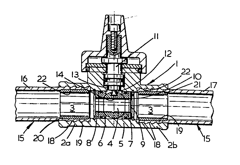
(57) A pipe joint is formed between first and second components wherein the first component
(1) comprises a sleeve (2a, 2b) and the second component (16,17) comprises a length
of resilient plastics pipe. The interior surface of the sleeve (2a, 2b) is provided
with a series of ridge and groove formations (18,19) and the plastics pipe (16,17)
is inserted into the sleeve (2a, 2b) and retained therein by means of a rigid insert
(20,21). The rigid insert (20,21) is located within that portion of the pipe (16,17)
lying within the sleeve (2a, 2b) and causes expansion of the pipe (16,17) radially
whereby the outer pipe surface engages the ridge and groove formations (18,19) and
takes up a complementary shape thereto to form said joint with the first component(1).
|
|
[0001] The present invention relates to a pipe joint between two components.
[0002] Recently, it has become common practice to use pipes made of resilient plastics material
for distribution purposes such as domestic gas supply pipes leading into consumers'
properties. It is often necessary to include in these pipes components such as isolation
valves, which must be high integrity valves and corrosion resistant, and it is therefore
necessary for high integrity joints to be made between these pipes and the components.
Difficulty has often arisen in the past as a result of the plastics pipes and the
components being made of different materials so that production of a high integrity
joint involves producing a transition fitting which is compatible with both materials.
[0003] The object of the present invention is to provide a pipe joint which is suitable
for use with resilient plastics pipes and fittings.
[0004] According to the present invention there is provided in a combination of first and
second components, a pipe joint between the components wherein the first component
comprises a sleeve and the second component comprises a length of resilient plastics
pipe which is inserted into the sleeve and retained therein characterised in that
the interior surface of the sleeve is provided with a series of ridge and groove formations
and the plastics pipe is retained therein by means of a rigid insert which is located
within that portion of the pipe lying within the sleeve and which causes expansion
of the pipe radially whereby the outer pipe surface engages the ridge and groove formations
and takes up a complementary shape thereto to form said joint with the first component.
[0005] The present invention will now be described by way of example with reference to the
accompanying drawing which is a cross-sectional view of a rotary ball valve jointed
into a pipeline.
[0006] The rotary ball valve comprises a main body 1 including coaxial sleeves 2a and 2b
which form the inlet and the outlet of a fluid flow passage 3 through the valve. An
apertured ball member 4 is disposed within a central cylindrical portion 5 of the
passage 3, which portion is of a smaller diameter than the sleeves 2a and 2b. The
ball member 4 is located between a pair of valve seat members 6 and 7 which are also
disposed within the central portion 5. The valve seat member 6 abuts against a fixed
insert 8 located within the portion 5 whereas the seat member 7 is acted upon by the
force of a Belleville spring washer 9 which abuts against a second fixed insert 10
also located within the portion 5. In this way the ball member 4 is clamped between
the seat member 6 and 7 with an approximately constant pressure being exerted thereon,
the spring washer 9 taking up slack as the ball member 4 and the seat members 6 and
7 wear.
[0007] A valve stem 11 is mounted for rotation in an upstanding part of the main body 1
and has a projecting key piece 12 which extends through a hole 13 in the central portion
5 and engages an aperture 14 in the surface of the ball member 4. This arrangement
is such that the ball member 4 can be turned by the valve stem 11 to open or close
the valve.
[0008] The flow passage 3 of the ball valve is connected to pipework 15 which is made of
a resilient plastics material, such as polyethylene. The pipework 15 may comprise
transition pipework, which comprises short lengths of pipe for connection into a main
pipeline or other components in a pipeline, or may comprise longer lengths of pipe
which form a direct part of a pipeline. As shown in the drawing, lengths of pipe 16
and 17 are connected to the sleeves 2a and 2b respectively.
[0009] The interior surface of each of the sleeves 2a and 2b is configured to provide a
series of ridge and groove formations 18 and 19 respectively formed annularly around
the interior surfaces of the sleeves 2a and 2b. The pipes 16 and 17 are partially
inserted into the sleeves 2a and 2b and rigid annular inserts 20 and 21 are located
respectively within those portions of the pipes 16 and 17 lying within the sleeves
1 and 2. The inserts 20 and 21 are preferably made of metal such as for example steel,
and must have an outer diameter sufficiently large to cause expansion of the diameter
of the pipes l6 and 17 whereby the outer surfaces 22 of the pipes 16 and 17 are expanded
radially to engage the ridge and groove formations 18 and 19 and to take up a complementary
shape thereto. In this way a strong gas-tight joint can be formed.
[0010] The joint is produced by the insertion of one end of the pipes 16 and 17 into the
sleeves 1 and 2 respectively and thereafter forcing the inserts 20 and 21 down the
pipes 16 and 17 from their free ends until the inserts 20 and 21 are also located
within the sleeves 1 and 2.
[0011] The body 1 of the valve would preferably be made of metal for domestic gas supply
services and the abovedescribed joint provides a means of successfully connecting
a plastics pipe to the metal valve. However, to prevent corrosion of the body 1 if
the valve is to be located underground, the body 1 is preferably coated with a layer
of resilient plastics material, such as polyethylene or another similar plastics material.
[0012] The joint is also improved in strength if the ridge and groove formations 18 and
19 are produced so that sharp right-angled corners are avoided. Preferably, the angles
between the grooves and ridges are oblique as shown on the drawing.
[0013] This prevents the plastics pipes 16 and 17 from being easily sheared out of the sleeves
1 and 2 which can be caused by sharp right-angle corners cutting into the plastics
pipes 16 and 17 so that they free themselves from the sleeves 1 and 2.
1. In a combination of first and second components, a pipe joint between the components
wherein the first component comprises a sleeve and the second component comprises
a length of resilient plastics pipe which is inserted into the sleeve and retained
therein characterised in that the interior surface of the sleeve (2a, 2b) is provided
with a series of ridge and groove formations (18, 19) and the plastics pipe (16, 17)
is retained therein by means of a rigid insert (20,21) which is located within that
portion of the pipe (16, 17) lying within the sleeve (2a, 2b) and which causes expansion
of the pipe (16, 17) radially whereby the outer pipe surface (22) engages the ridge
and groove formations (18, 19) and takes up a complementary shape thereto to form
said joint with the first component (1).
2, A pipe joint as claimed in claim 1, characterised in that the ridge and groove
formations (18, 19) are annular around the interior surface of the sleeve (2a, 2b).
3. A pipe joint as claimed in claim 1 or 2, characterised in that the insert (20,
21) comprises an annular insert with an outer diameter sufficiently large to cause
radial expansior of the pipe (16, 17) when inserted therein.
4. A pipe joint as claimed in any one of claims 1 to 3, characterised in that the
angles between the grooves (19) and ridges (18) of the ridge and groove formations
are oblique.
5. A pipe joint as claimed in any one of claims 1 to 4, characterised in that the
first component (1) comprises a metal component, the exterior surface of which is
covered by a layer of plastics material.
