| (19) |
 |
|
(11) |
EP 0 040 981 B1 |
| (12) |
EUROPEAN PATENT SPECIFICATION |
| (45) |
Mention of the grant of the patent: |
|
24.04.1985 Bulletin 1985/17 |
| (22) |
Date of filing: 26.05.1981 |
|
|
| (54) |
A sleeve bearing, a sleeve bearing half-shell and a split-angle end rod assembly
Schalenlager, Schalenlager-Halbschale und eine unter einem Winkel geteilte Pleuelstangenkopf-Anordnung
Palier à coquilles, demi-coussinet de palier à coquilles et disposition d'une tête
de bielle fendue sous un angle
|
| (84) |
Designated Contracting States: |
|
DE FR GB IT |
| (30) |
Priority: |
27.05.1980 US 153249
|
| (43) |
Date of publication of application: |
|
02.12.1981 Bulletin 1981/48 |
| (71) |
Applicant: FEDERAL-MOGUL CORPORATION |
|
Southfield
Michigan 48075 (US) |
|
| (72) |
Inventor: |
|
- Roberts, Arden J.
Warren
Michigan 48092 (US)
|
| (74) |
Representative: Wisher, Michael Frederick et al |
|
6 Elwill Wey
GB-Beckenham, Kent BR3 3AD
GB-Beckenham, Kent BR3 3AD (GB) |
|
| |
|
| Note: Within nine months from the publication of the mention of the grant of the European
patent, any person may give notice to the European Patent Office of opposition to
the European patent
granted. Notice of opposition shall be filed in a written reasoned statement. It shall
not be deemed to
have been filed until the opposition fee has been paid. (Art. 99(1) European Patent
Convention).
|
[0001] This invention relates generally to sleeve bearings and is particularly concerned
with a sleeve bearing adapted to have an oil film or layer between the bearing surface
and a journalled member. The invention is particularly applicable to half-shell sleeve
bearings used in internal combustion engines in co-operation with crankshafts and
connecting rods. However, it will be appreciated that the invention has broader applications
and may be used in other environments of this general type.
[0002] Engine main and connecting rod bearings in internal combustion engines are subjected
to repetitive loads which can ultimately fatique the bearing. The bearings are disposed
in a continuously circulated oil bath and there is a clearance provided between the
outer peripheral surface of the journalled member or crankshaft and the inner peripheral
bearing surface of the sleeve bearing. This facilitates relative rotation between
the parts during normal engine operation and facilitates the creation of an oil film
between the parts which act as a load supporting medium during engine operation. The
hydrodynamic wedge effect of the oil causes the shaft or journalled member to float
on an oil film as a result of there being a difference between the shaft and bearing
radii, i.e. a clearance. The oil in the clearance provides lubrication and cooling.
It has been shown that the oil film pressure developed in such bearings increases
with increased bearing
'clearance. Bearings exposed to higher pressures fatigue sooner or to a greater extent
than bearings exposed to lower pressures. A greater clearance provides a greater oil
film pressure and a greater oil film pressure causes the bearing to fatigue faster.
It seemingly would be a mere matter of reducing the oil film clearance to reduce the
oil film pressure to increase the bearing life. The clearance cannot simply be reduced,
however, as that would reduce the lubrication and cooling and causing the bearing
to run hotter and possibly burn up during operation.
[0003] It has been proposed to provide sleeve bearings with a portion of the bearing surface
having a radius nearly equal to the radius of the journalled member so as to reduce
the clearance during the high-load portion of the bearing cycle to reduce oil film
pressure and a second portion with a greater clearance. An example of such a bearing
is shown in United States Patent No. 4,073,550 granted February 14, 1978. In that
bearing assembly the sleeve bearing is made of two half-shells with one of the half-shells
having a radius which closely approximates the radius of the journalled member to
reduce clearance and with the second half-shell having a bearing surface of a greater
radius to increase clearance. That sleeve bearing must be fabricated from two different
half-shells and is subjected to wear at the juncture between the half-shells where
there is a step, as the bearing surfaces do not coincide. Another sleeve bearing having
a second portion of the bearing surface for clearance is illustrated in United States
patent No. 3,625,580 granted December 7, 1981. That bearing, however, includes two
opposed portions of the bearing surface which are concentric to the journalled member
and because a given diametrical clearance is required in a bearing sleeve, both of
these proposed surfaces must contribute to that total diametrical clearance, whereby
there is a limit in the reduction of such clearances.
[0004] Other proposals in this field of the art include DE-A-23 59 634 and GB-A-715 927.
In the British Specification there is disclosed a bearing for a split-angle end rod
assembly in which a pair of bearing shells provide bearing areas of differing clearance
around the periphery of a journalled member. Four quadrants of differing clearance
are provided, the quadrants being arranged in diametrically opposed relationship with
the areas of greater clearance opposite each other to provide wedge spaces for promoting
maintenance of an effective oil film. However, these "wedge spaces" are relatively
short in circumferential extent and each one tapers off and terminates at the end
or parting edge of its half-shell and in practice it is desirable to improve this
arrangement.
[0005] An object of the present invention is to provide a sleeve bearing half-shell together
with a sleeve bearing comprising a pair of such shells and a split-angle end rod assembly
offering improvements in relation to one or more of the technical shortcomings of
the prior proposals discussed above.
[0006] According to the invention there is provided a sleeve bearing half-shell, and a sleeve
bearing, and a split angle end rod assembly, as defined in the accompanying claims.
[0007] In an embodiment of the invention described below there is provided a bearing assembly
having a bearing surface with a first portion extending circumferentially on a constant
radius for close or reduced clearance with respect to a member journalled therein,
and the bearing surface has a second circumferential portion which lies radially outside
the circle defined by said constant radius, to provide a greater clearance. The bearing
area providing reduced clearance is arranged to be in close proximity to the journalled
member during the high-load portion of each revolution.
[0008] Embodiments of the invention will now be described by way of example with reference
to the accompanying drawings in which:
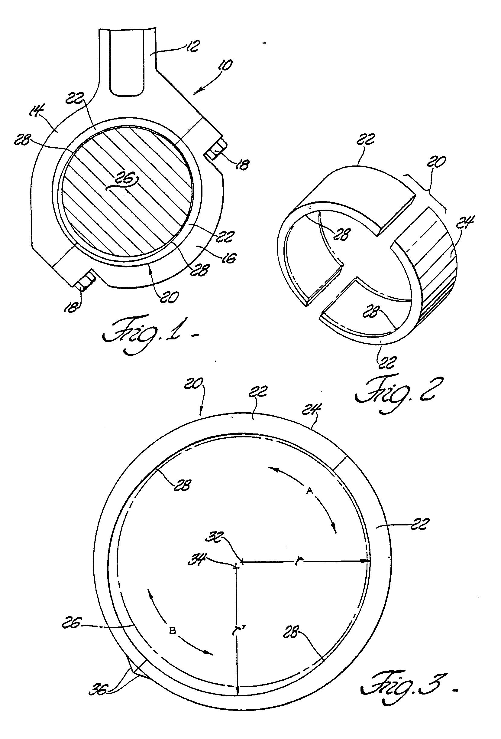
FIGURE 1 is a fragmentary elevational view of a split-angle end rod assembly incorporating
a sleeve bearing in accordance with the subject invention;
FIGURE 2 is a perspective view of the sleeve bearing shown in FIGURE 1;
FIGURE 3 is an enlarged side view of one embodiment of the sleeve bearing of the subject
invention, and
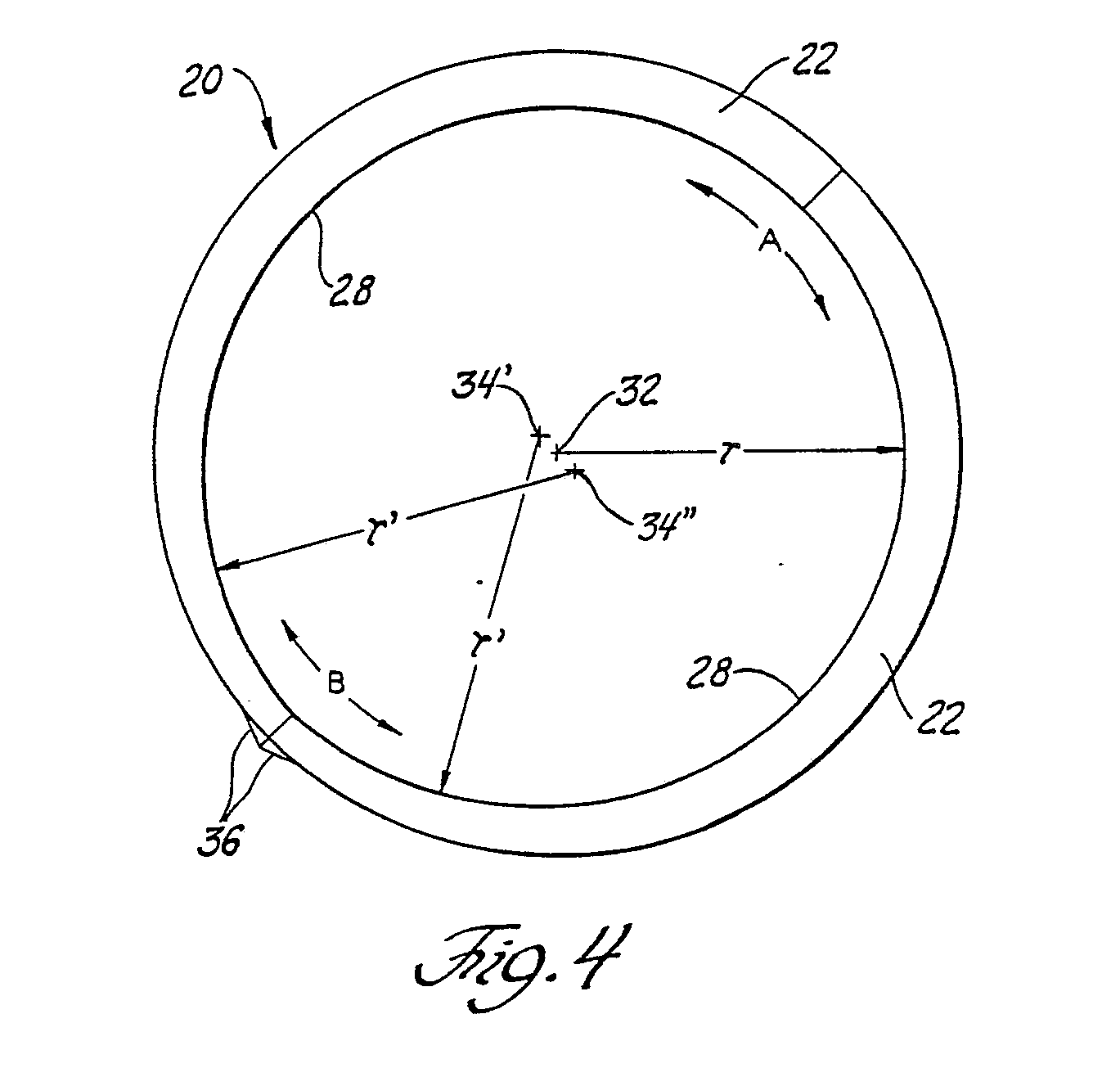
FIGURE 4 is an enlarged side view of another embodiment of the sleeve bearing of the
subject invention.
[0009] A split-angle end rod assembly is generally shown at 10. The assembly 10 includes
an elongated rod 12 having a longitudinal axis and integral with an upper bearing
housing 14. A separate lower bearing housing 15 is included and is connected to the
upper bearing housing 14 by fastening means comprising the bolts 18. The bolts 18
extend through the lower bearing housing 16 and threadedly engage the upper bearing
housing 14 to secure the two housings 14 and 16 together whereby the housings 14 and
16 define a circular bearing pocket. Each of the housings 14 and 16 provides one-half
of the circular circumference of the bearing pocket. The housings 14 and 16 mate on
a diameter which is disposed on or at an acute angle relative to the longitudinal
axis of the rod 12.
[0010] A sleeve bearing generally shown at 20 is disposed in the circular bearing pocket
defined by the housings 14 and 16. The bearing 20 is made of two half-shells 22 and
has an outer cylindrical surface 24 engaging the bearing pocket defined by the housings
14 and 16. The sleeve bearing 20 includes an inner bearing surface surrounding a cylindrical
journalled member 26 in close spaced relationship therewith in a manner defining a
clearance space with the journalled member to receive lubricant.
[0011] The inner bearing surface has a circular first portion extending circumferentially
as generally indicated at A on a constant radius r between the spaced locations 28.
The bearing surface includes a second portion extending circumferentially as generally
indicated by B and is disposed outside the constant radius r and joins the first portion
at or on the constant radius at the spaced locations 28. Each of the half-shells 22
include one-half of each of the first and second bearing portions between the locations
28. As illustrated in FIGURE 1, one of the half-shells 22 is disposed in the bearing
housing 14, and the other half-shell 22 is disposed in the bearing housing 16. The
second bearing portion generally indicated at B extends circumferentially on a constant
radius r'. The constant radius r of the first portion A extends about a first axis
32 and the constant radius r' of the second portion B extends about a second or reference
axis 34. The axes 32 and 34 are spaced from one another and are disposed on the diameter
which divides the first and second portions A and B in half. In other words, the axes
32 and 34 are on the diameter which divides the first and second portions A and B
and divides the half-shells 22, the half-shells being semi-circular. The axes 32 and
34 are on the diameter along which the half-shells 22 mate. The constant radius r'
of the second portion B is not less than the length of the constant radius r of the
first portion A. In other words, the radius r' is not less than the radius r, although
it is preferably greater.
[0012] The bearing surface on the constant radius r extending generally over the area A
between the locations 28 closely approximates the radius of the journalled member
26, that is, there is very small clearance between the journalled member 26 and the
bearing surface on the constant radius r. The bearing surface on the constant radius
r is concentric with the outer cylindrical surface 24 of the sleeve and will, therefore,
be nearly concentric with the journalled member 26. However, the second bearing portion
on the radius r' generally indicated at B and extending between the locations 28 is
eccentric with respect to the outer cylindrical surface 24 thereby providing a greater
clearance between the journalled member and the sleeve bearing over the bearing surface
B.
[0013] The half-shells 22 are identical to one another, as they each include a bearing surface
extending 180° with a first portion A extending circumferentially on the constant
radius r and a second portion extending the remainder of the circumference and disposed
outside the constant radius r with the two bearing surface portions A and B meeting
at location 28 in each half-shell which is on the constant radius r.
[0014] The arc over which the bearing portion A extends may vary but is preferably less
than 180° in the sleeve bearing. In other words, the bearing portion A in each half-shell
extends circumferentially less than 90° and the bearing portion B extends greater
than 90°.
[0015] Each of the half-shells 22 includes a locating projection 36, as is well known in
the art.
[0016] As will be appreciated, the bearing surface portion on the constant radius r provides
a very close clearance with the journalled member 26 during the loaded portion of
each revolution to main a very thin oil film to reduce oil film pressure and thereby
increase resistance to bearing fatigue. However, the second portion of the bearing
surface on the radius r' extending generally over the area B between the locations
28 is outside the radius r or is eccentric to provide greater clearance to provide
the proper oil flow through the bearings to control the bearing temperature. The two
bearing surfaces meet at location 28 which is on the constant radius r to provide
a smooth transition between the bearing surface portions. Thus, the sleeve bearing
is made of two identical half-shells which reduce clearance and, consequently, oil
film pressure during the loaded portion of each revolution but because of the eccentrically
disposed bearing portion B the normal clearance is provided to provide the required
oil flow.
[0017] The embodiment shown in FIGURE 4 incorporates the features and provides the advantages
discussed above in connection with the first embodiment. The embodiment of FIGURE
4 differs from the first-described embodiment only in that the entirety of the second
portion B in the first embodiment extends about the reference axis 34 on the constant
radius r', whereas in the embodiment of FIGURE 4 the second portion B on one side
of the dividing diameter extends on the constant radius r' about a first reference
axis 34' and on the other side of the diameter extends on the constant radius r' about
a second reference axis 34". The first and second reference axes 34' and 34" are spaced
from one another and from the first axis 32. Also, the first and second axes 34' and
34" are equally spaced on opposite sides of the dividing diameter. In other words,
the half-shells in FIGURE 4 are identical to one another as the orientation or disposition
of the first reference axis 34' relative to its half-shell is exactly the same as
that of the second reference axis 34" to its half-shell.
[0018] The invention has been described in an illustrative manner, and it is to be understood
that the terminology which has been used is intended to be in the nature of words
of description rather than of limitation.
[0019] Obviously, many modifications and variations of the present invention are possible
in light of the above teachings. It is, therefore, to be understood that within the
scope of the appended claims wherein reference numerals are merely for convenience
and are not to be in any way limiting, the invention may be practised otherwise than
as specifically described.
1. A sleeve bearing (20) having an outer cylindrical surface (34) and an inner bearing
surface adapted to surround a cylindrical journalled member (26) in closely spaced
relationship therewith in a manner defining a clearance space with the journalled
member (26) to receive lubricant, said bearing surface having a circular first portion
(A) extending circumferentially between spaced locations (28) about a first axis (32)
on a first constant radius (r) which closely approximates to the radius of the journalled
member (26) so that said first portion (A) is substantially concentric with the journalled
member (26) when cooperating therewith during the loaded portion of a revolution,
said bearing surface having a second portion (B) extending circumferentially outside
the circle defined by said first constant radius (r), characterised in that said second
portion (B) joins said first portion (A) at said spaced locations (28) on said first
constant radius (r) and is defined by one or more circular arcs of second constant
radius (r'), the respective reference axis (34, 34', 34") for the or each said arc
being eccentric with respect to said first axis (32).
2. A sleeve bearing according to claim 1 characterised in that said second constant
radius (r') is not less than said first constant radius (r) of said first portion
(A).
3. A sleeve bearing according to claim 1 or claim 2 characterised in that the sleeve
bearing (20) comprises a pair of semi-circular half-shells (22).
4. A sleeve bearing according to claim 3 characterised in that said half-shells (22)
engage one another on a diameter which divides each of said first (A) and second (B)
portions of said bearing surface, so that said half-shells (22) are identical.
5. A sleeve bearing according to claim 4 characterised in that said first portion
(A) is concentric with said outer cylindrical surface (24) and said second portion
(B) is eccentric with respect to said outer cylindrical surface (24).
6. A sleeve bearing according to claim 4 or claim 5 characterised in that said reference
axis (34) is also located on said diameter.
7. A sleeve bearing according to claim 4 or claim 5 characterised in that said second
portions (B) of said bearing surface on one side of said diameter extends about a
first reference axis (34') on said second constant radius (r') and on the other side
of said diameter extends about a second reference axis (34") on said second constant
radius (r').
8. A sleeve bearing according to claim 7 characterised in that said first and second
reference axes (34', 34") are equally spaced on opposite sides of said diameter.
9. A sleeve bearing according to claim 1 or claim 2 characterised in that said sleeve
(20) comprises a pair of semi-circular half-shells (22), and that in each of said
half-shells (22) defines one half of each of said first (A) and second (B) portions
of said bearing surface so that said half-shells (22) are identical.
10. A sleeve bearing according to claim 9 characterised in that said first portion
(A) of said bearing surface is concentric with said outer cylindrical surface (24)
and said second portion (B) of said bearing surface is eccentric with respect to said
outer cylindrical surface (24).
11. A sleeve bearing half-shell (22) having an outer cylindrical surface (24) and
an inner bearing surface adapted to receive a journalled member (26), said bearing
surface extending 180 degrees and consisting of a first portion (A) beginning at one
parting face and extending circumferentially on a first constant radius (r) about
an axis (32) for a part of the 180 degrees, and a second portion (B) generated about
a reference axis (34, 34', 34") eccentric to axis (32) and which begins at the other
parting face and extends circumferentially outside the circle defined by said constant
radius (r) for the remains of the 180 degrees and joins said first bearing surface
portion (A) at a location (28) on said constant radius (r), characterised in that
the junction of said second portion (B) with said other parting face also lies outside
the circle defined by said constant radius (r).
12. A sleeve bearing half-shell according to claim 11 characterised in that said first
portion (A) of said bearing surface is concentric with said outer cylindrical surface
(24).
13. A sleeve bearing half-shell according to claim 12 characterised in that said second
portion (B) of said bearing surface extends circumferentially on a second constant
radius (r') which is not less than said first constant radius (r) of said first portion
(A).
14. A sleeve bearing half-shell according to claim 13 characterised in that said second
portion (B) of said bearing surface is eccentric to said outer cylindrical surface
(24).
15. A sleeve bearing half-shell according to any one of claims 11 to 14 characterised
in that said first portion (A) of said bearing surface extends circumferentially less
than 90 degrees and said second portion (B) extends circumferentially more than 90
degrees.
16. A split angle end rod assembly (10) comprising an elongated rod (12) having a
longitudinal axis and integral with an upper bearing housing (14), a separate lower
bearing housing (16), fastening means (18) for securing said housings (14, 16) together
to define a circular bearing pocket, each of said housings (14, 16) providing one
half of the circular circumference of said pocket, said housings (14, 16) mating on
a diameter which is disposed at an acute angle relative to said longitudinal axis
of the rod (12), a sleeve bearing (20) disposed in said pocket, the sleeve bearing
(20) comprising two half-shells (22), one of said half-shells (22) being disposed
in one (14) of said bearing housings and the other half-shell (22) being disposed
in the other (16) of said bearing housings, said sleeve bearing (20) having an outer
cylindrical surface (24) engaging said pocket and an inner bearing surface adapted
to surround a cylindrical journalled member (26) in closely spaced relationship therewith
in a manner defining a clearance space with respect to the journalled member (26)
to receive lubricant, the bearing surface having a first portion (A) adapted to be
concentric with the journalled member (26) during the loaded portion of a revolution
and extending circumferentially between spaced locations (28) on a constant radius
(r) which closely approximates to the radius of the journalled member (26) to provide
a relatively small clearance with respect to the journalled member (26), characterised
in that a second portion (B) of the bearing surface is adapted to be eccentric with
respect to the journalled member (26) and extends radially outside the circle defined
by said constant radius (r) and joins said first portion (A) at said spaced locations
(28) on said constant radius (r), and each of said half-shells (22) includes one half
of each of said first (A) and second (B) portions of the bearing surface.
1. Gleitlager mit einer äußeren Zylinderfläche (24) und mit einer inneren Lauffläche,
die einen zylindrischen Lagerzapfen (26) in geringem Abstand umfaßt und mit dem Lagerzapfen
(26) einen Zwischenraum zur Aufnahme eines Schmiermittels bildet, wobei die Lauffläche
einen ersten kreisförmigen Abschnitt (A) aufweist, der sich am Umfang zwischen zwei
im Abstand befindlichen Orten (28) über einer ersten Achse (23) mit einem ersten konstanten
Radius (r) erstreckt, der annähernd dem Radius des Lagerzapfens (26) entspricht, so
daß der erste Abschnitt (A) im wesentlichen konzentrisch zum Lagerzapfen (26) ist,
wenn er während dem belasteten Teil einer Umdrehung mit dem Lagerzapfen (26) zusammenwirkt,
und wobei die Lauffläche einen zweiten Abschnitt (B) aufweist, der sich am Umfang
außerhalb des durch den ersten konstanten Radius (r) definierten Kreises erstreckt,
dadurch gekennzeichnet, daß der zweite Abschnitt (B) mit dem ersten Abschnitt (A)
an den im Abstand liegenden, den ersten konstanten Radius (r) aufweisenden Orten (28)
zusammentrifft und durch einen oder mehrere Kreisbögen mit einem zweiten konstanten
Radius (r') definiert ist, dessen/oder deren zugeordnete Referenz-Achsen (34, 34',
34") jeweils exzentrisch zur ersten Achse (32) sind.
2. Gleitlager nach Anspruch 1, dadurch gekennzeichnet, daß der zweite konstante Radius
(r') nicht kleiner als der erste konstante Radius (r) des ersten Abschnitten (A) ist.
3. Gleitlager nach Anspruch 1 oder 2, dadurch gekennzeichnet, daß das Gleitlager (20)
ein Paar halbkreisförmige Halbschalen (22) umfaßt.
4. Gleitlager nach Anspruch 3, dadurch gekennzeichnet, daß die beiden Halbschalen
(22) einander identisch ausgebildet sind und an dem Durchmesser miteinander in Eingriff
stehen, durch den jeder des ersten (A) und es zweiten (B) Abschnittes der Lauffläche
geteilt ist.
5. Gleitlager nach Anspruch 4, dadurch gekennzeichnet, daß der erste Abschnitt (A)
konzentrisch zur äußeren zylindrischen Fläche (24) und daß der zweite Abschnitt (B)
exzentrisch in bezug auf die äußere zylindrische Fläche (24) ist.
6. Gleitlager nach den Ansprüchen 4 oder 5, dadurch gekennzeichnet, daß die Bezugsachse
(34) ebenfalls am Orte des die Laufflächen des ersten (A) und des zweiten (B) Abschnittes
teilenden Durchmessers angeordnet ist.
7. Gleitlager nach den Ansprüchen 4 oder 5, dadurch gekennzeichnet, daß der zweite
Abschnitt (B) der Lauffläche auf einer Seite des Durchmesser sich über einer ersten
Referenzachse (34') mit dem zweiten konstanten Radius (r') erstreckt und auf der anderen
Seite des Durchmessers sich über einer zweiten Referenzachse (34") mit dem zweiten
konstanten Radius (r') erstreckt.
8. Gleitlager nach Anspruch 7, dadurch gekennzeichnet, daß die erste und die zweite
Referenzachse (34', 34") in gleichen Abstand auf gegenüberliegenden Seiten des Durchmesser
haben.
9. Gleitlager nach Anspruch 1 oder 2, dadurch gekennzeichnet, daß das Gleitlager (20)
ein Paar halbkreisförmiger Halbschalen (22) aufweist, und daß jede der Halbschalen
(22) je eine Hälfte des ersten (A) und des zweiten (B) Abschnittes der Lauffläche
definiert derart, daß beide Halbschalen (22) identisch sind.
10. Gleitlager nach Anspruch 9, dadurch gekennzeichnet, daß der erste Abschnitt (A)
der Lauffläche konzentrisch zur äußeren zylindrischen Fläche (24) und der zweite Abschnitt
(B) der Lauffläche exzentrisch in bezug auf die äußere zylindrische Fläche (24) ist.
11. Gleitlager-Halbschale (22) mit einer äußeren zylindrischen Fläche (24) und einer
einen Lagerzapfen (26) aufnehmende innere Lauffläche, die sich über 180° erstreckt,
und eine ersten Abschnitt (A), der an einer Trennfläche beginnt und sich über den
Umfang mit einem ersten konstanten Radius (r) auf einer Achse (32) über 180° erstreckt,
sowie eine zweiten Abschnitt (B) umfaßt, der um zur Achse (32) exzentrische Referenzachsen
(34, 34', 34") erzeugt ist und an der anderen Trenfläche beginnend sich über den Umfang
außerhalb des durch den konstanten Radius (r) bestimmten Kreises über den Rest der
180° erstreckt und mit dem ersten Laufflächen-Abschnitt (A) an einem Orte (28) mit
dem konstanten Radius (r) verbunden ist, dadurch gekennzeichnet, daß die Verbindung
des Zweiten Abschnittes (B) mit der anderen Trennfläche ebenfalls außerhalb des durch
den konstanten Radius (r) definierten Kreises liegt.
12. Gleitlager-Halbschale nach Anspruch 11, dadurch gekennzeichnet, daß der erste
Abschnitt (A) der Lauffläche konzentrisch zur äußeren zylin- drischen Fläche (24) ist.
13. Gleitlager-Halbschale nach Anspruch 12, dadurch gekennzeichnet, daß der zweite
Abschnitt (B) der Lauffläche sich längs des Umfanges erstreckt, der durch eine zweiten
konstanten Radius (r') definiert ist, der nicht kleiner als der erste Radius (r) des
ersten Abschnittes (A) ist.
14. Gleitlager-Halbschale nach Anspruch 13, dadurch gekennzeichnet, daß der zweite
Abschnitt (B) der Lauffläche exzentrisch zu der äußeren zylindrischen Fläche (24)
ist.
15. Gleitlager-Halbschale nach einem der vorhergehenden Ansprüche 11 bis 14, dadurch
gekennzeichnet, daß der erste Abschnitt (A) sich über den Umfang um weniger als 90°
erstreckt und daß sich der zweite Abschnitt (B) über den Umfang um mehr als 90° erstreckt.
16. Anordnung (10) mit einer langgestreckten Kolbenstange (12) mit einer Längsachse
und einem integralen oberen Lagergehäuse (14), mit einem getrennten unteren Lagergehäuse
(16), mit Befestigungsmitteln (18) für das Verbinden beider Gehäuse (14, 16) miteinander
zwecks Bildung einer kreisförmigen Lagertasche, wobei jedes der Lagergehäuse (14,
16) eine Hälfte des kreisförmigen Umfangs der Lagertasche bildet und die Lagergehäuse
(14, 16) an einem Durchmesser aufeinander treffen, der einen spitzen Winkel mit der
Längsachse der Kolbenstange (12) einschließt, ein in der Lagertasche angeordnetes
Gleitlager (20), das aus zwei Gleitlager-Halbschalen (22) besteht, von denen eine
(22) in dem einen Lagergehäuse (14) und die andere (22) in dem Anderen Lagergehäuse
(16) angeordnet ist, wobei das Gleitlager (20) eine äußere in der Lagertasche anliegende
zylindrische Fläche (24) und eine innere Lauffläche aufweist, welche eine zylindrischen
Zapfen (26) in engem Abstand umfaßt und mit diesem einen Zwischenraum zur Aufnahme
eines Schmiermittels Bildet, und wobei die Lauffläche einen ersten während dem belasteten
Teil einer Umdrehung zum Lagerzapfen (26) konzentrischen Abschnitt (A) aufweist, der
sich am Umfang zwischen im Abstand befindlichen Orten (28) erstreckt, die auf einem
konstanten Radius (r) liegen, der annähernd dem Radius des Lagerzapfens (26) entspricht
zwecks Bildung eines relativ engen Zwischenraumes in bezug auf den Lagerzapfen (26),
dadurch gekennzeichnet, daß ein zweiter Abschnitt (B) der Lauffläche in bezug auf
den Lagerzapfen (26) exzentrisch angeordnet ist und sich radial außerhalb des durch
den konstanten Radius (r) definierten Kreises befindet und mit dem ersten Abschnitt
(a) an den im Abstand voneinander liegenden Orten (28) verbunden ist, die auf dem
konstanten Radius (r) liegen, und dab jede der Halbschalen (22) je eine Hälfte des
ersten (A) und des zweiten (B) Abschnittes der Lauffläche umfassen.
1. Coussinet de palier (20) présentant une surface cylindrique extérieure (24) et
une surface de porté intérieure prévue pour entourer une pièce cylindrique supportée
(26) à faible distance de celle-ci de manière à définir un jeu avec la pièce supportée
(26) pour recevoir un lubrifiant, la surface de portée comprenant une première partie
circulaire (A) qui s'étend circonférentiellement, entre des positions espacées (28),
autour d'un premier axe (32) et avec un premier rayon constant (r) très voisin du
rayon de la pièce supportée (26) de sorte que la première partie (A) est sensiblement
concentrique à la pièce supportée (26) lorsqu'elle coopère avec elle pendant la partie
chargée d'une révolution, la surface de portée comprenant une deuxième partie (B)
qui s'étend circonférentiellement à l'extérieur du cercle défini par le premier rayon
constant (r), caractérisé en ce que la deuxième partie (B) se raccorde à la première
partie (A) auxdites positions espacées (28) sur le premier rayon constant (r) et est
définie par un ou plusieurs arcs de cercle d'une deuxième rayon constant (r'), l'axe
de référence respectif (34, 34', 34") pour l'arc ou chaque arc étant excentré par
rapport au premier axe (32).
2. Coussinet suivant la revendication 1, caractérisé en ce que le deuxième rayon constant
(r') n'est pas inférieur au premier rayon constant (r) de la première partie (A).
3. Coussinet suivant la revendication 1 ou la revendication 2, caractérisé en ce que
le coussinet (20) comprend deux demi-coquilles (22) semi- circulaires.
4. Coussinet suivant la revendication 3, caractérisé en ce que les demi-coquilles
(22) sont en contact l'une avec l'autre suivant un diamètre qui divise chacune des
première (A) et deuxième (B) parties de la surface de portée, de sorte que les demi-coquilles
(22) sont identiques.
5. Coussinet suivant la revendication 4, caractérisé en ce que la première partie
(A) est concentrique à la surface cylindrique extérieure (24) et la deuxième partie
(B) est excentrée par rapport à la surface cylindrique extérieure (24).
6. Coussinet suivant la revendication 4 ou la revendication 5, caractérisé en ce que
l'axe de référence (34) est également situé sur ledit diamètre.
7. Coussinet suivant la revendication 4 ou la revendication 5, caractérisé en ce que
la deuxième partie (B) de la surface de portée, d'un côté dudit diamètre, est centrée
sur un premier axe de référence (34') avec le deuxième rayon constant (r') et, de
l'autre côté dudit diamètre, est centrée sur un deuxième axe de référence (34") avec
le deuxième rayon constant (r').
8. Coussinet suivant la revendication 7, caractérisé en ce que les premier et deuxième
axes de référence (34', 34") sont également espacés de chaque côté dudit diamètre.
9. Coussinet suivant la revendication 1 ou la revendication 2, caractérisé en ce que
ce coussinet (20) comprend deux demi-coquilles (22) semi- circulaires et en ce que
chacune des demi-coquilles (22) comprend une moitié de chacune des première (A) et
deuxième (B) parties de la surface de portée, de sorte que les demi-coquilles (22)
sont identiques.
10. Coussinet suivant la revendication 9, caractérisé en ce que la première partie
(A) de la surface de portée est concentrique à la surface cylindrique extérieure (24)
et la deuxième partie (B) de la surface de portée est excentrée par rapport à la surface
cylindrique extérieure (24).
11. Demi-coquille (22) pour coussinet de palier, présentant une surface cylindrique
extérieure (24) et une surface de portée intérieure prévue pour recevoir une pièce
supportée en rotation (26), la surface de portée s'étendant sur 180 degrés et comprenant
une première partie (A), qui commence à une face de séparation et s'étend circonférentiellement
avec une premier rayon constant (r) autour d'un axe (32) pour une partie des 180 degrés,
et une deuxième partie (B) engendrée autour d'un axe de référence (34, 34', 34"),
excentré par rapport à l'axe (32), et qui commence à l'autre face de séparation et
s'étend circonférentiellement à l'extérieur du cercle défini par le rayon constant
(r) pour le reste des 180 degrés et se raccorde à la première partie (A) de la surface
de portée à une position (28) sur le rayon constant (r), caractérisée en ce que la
jonction de la deuxième partie (B) avec l'autre face de séparation se trouve également
à l'extérieur du cercle défini par le rayon constant (r).
12. Demi-coquille de coussinet de palier suivant la revendication 11, caractérisée
en ce que la première partie (A) de la surface de portée est concentrique à la surface
cylindrique extérieure (24).
13. Demi-coquille de coussinet suivant la revendication 12, caractérisée en ce que
la deuxième partie (B) de la surface de portée s'étend circonférentiellement avec
un deuxième rayon constant (r') qui n'est par inférieur au premier rayon constant
(r) de la première partie (A).
14. Demi-coquille de coussinet suivant la revendication 13, caractérisée en ce que
la deuxième partie (B) de la surface de portée est excentrée par rapport à la surface
cylindrique extérieure (24).
15. Demi-coqijille -Ù*,e coussinet suivant l'une quelconque des revendications 11
à 14, caractérisée en ce que la première partie (A) de la surface de portée s'étend
circonférentiellement sur moins de 90 degrés et la deuxième partie (B) s'étend circonférentiellement
sur plus de 90 degrés.
16. Bielle à joint oblique d'extrémité (10), comprenant une tige allongée (12) à axe
longitudinal et solidaire d'une boîte supérieure de palier (14), une boîte inférieure
séparée de palier (16), des moyens de fixation (18) pour assembler les boîtes (14,
16) de manière à définir une poche circulaire de palier, chacune des boîtes (14, 16)
constituant une moitié de la circonférence circulaire de la poche, les boîtes (14,
16) se raccordant suivant un diamètre qui forme un angle aigu par rapport à l'axe
longitudinal de la tige (12), un coussinet (20) disposé dans la poche, le coussinet
(20) comprenant deux demi-coquilles (22), l'une des demi-coquilles (22) étant placée
dans l'unr (14) des boîtes de palier et l'autre demi-coquille (22) étant placée dans
l'autre (16) des boîtes de palier, le coussinet (20) présentant une surface cylindrique
extérieur (24) en contact avec la poche et une surface de portée intérieure prévue
pour entourer une pièce cylindrique (26) supportée en rotation, à faible distance
de celle-ci de manière à définir un jeu par rapport à la pièce supportée (26) pour
recevoir un lubrifiant, la surface de portée comprenant une première partie (A) prévue
pour être concentrique à la pièce supportée (26) pendant la partie chargée d'une révolution
et qui s'étend circonférentiellement entre des positions espacées (28) avec une rayon
constant (5) très voisin du rayon de la pièce supportée (26) de manière à créer un
jeu relativement petit par rapport à la pièce supportée (26), caractérisée en ce qu'une
deuxième partie (B) de la surface de portée est prévue pour être excentrée par rapport
à la pièce supportée (26) et s'étend radialement à l'extérieur du cercle défini par
le rayon constant (r) et se raccorde à la première partie (A) auxdites positions espacées
(28) sur le rayon constant (r), et en ce que chacune des demi-coquilles (22) comprend
une moitié de chacune des première
(1) et deuxième (B) parties de la surface de portée.