| (19) |
 |
|
(11) |
EP 0 049 079 A1 |
| (12) |
EUROPEAN PATENT APPLICATION |
| (43) |
Date of publication: |
|
07.04.1982 Bulletin 1982/14 |
| (22) |
Date of filing: 21.09.1981 |
|
| (51) |
International Patent Classification (IPC)3: B21D 5/14 |
|
| (84) |
Designated Contracting States: |
|
AT BE CH DE FR GB IT LI LU NL SE |
| (30) |
Priority: |
19.09.1980 AU 5658/80
|
| (71) |
Applicant: Hume, Kenneth Michael |
|
East Kew
Victoria (AU) |
|
| (72) |
Inventor: |
|
- Hume, Kenneth Michael
East Kew
Victoria (AU)
|
| (74) |
Representative: Hind, Raymond Stenton et al |
|
c/o MATHISEN, MACARA & Co.
European Patent Attorneys
Lyon House
Lyon Road
Harrow
Middlesex HA1 2ET
Harrow
Middlesex HA1 2ET (GB) |
|
| |
|
| (54) |
Method for rolling plate |
(57) There is disclosed a method and apparatus for rolling flat plate using a cylindrical
mandrel (12) and a plate gripper (11) to form a pipe having low pipe diameter to plate
thickness ratio by forming a notch or recess in the plate edge to be gripped so that
the combined radial dimension of the notched plate edge and gripper is no greater
than the plate thickness.
|

|
[0001] This invention relates to plate bending machines and particularly to a machine as
described in the inventor's earlier Australian Patent No.
-463,345. There is disclosed in the earlier patent specification a method and apparatus
wherein a plate is rolled to form a cylindrical article which comprises engaging a
leading edge of the plate with a projecting rib on a mandrel so that the plate is
tangential to the mandrel from the edge and rotating the mandrel while engaging the
remainder of the plate by pressure rollers or the like to curve the plate about the
mandrel.
[0002] The aim of the present invention is to modify and improve the therein disclosed method
and apparatus thereby ensuring that the edge of the plate is properly gripped by the
rib on the mandrel. More specifically, it is the aim of the invention to provide bending
for.plates of greater thickness than possible hitherto.
[0003] There is provided according to the present invention a method of rolling plate to
form a curved or cylindrical article including engaging:one edge of a length of plate
between a mandrel and gripping means on the mandrel and turning the mandrel to curve
the plate, the improvement comprising recessing or notching the edge of the plate
to be gripped such that the combined dimension of the notched plate and gripping means
is substantially the same as the plate thickness.
[0004] Conveniently the mandrel is turned in a direction towards the edge of the plate resulting
in the plate being forced against said gripping means to bring about said engagement
with said gripping means. A pair of pressure rollers are provided beneath said mandrel
for engagement with the plate surface upon lowering of the mandrel before or during
said engagement of the plate edge to ensure alignment of the plate edge with said
gripper by engaging the plate edge continuously against the mandrel surface over the
full length of the plate. A similar curving procedure is then followed as is disclosed
in the previously mentioned patent specification.
[0005] The edge engagement procedure as described above when gripping the edge opposite
said one edge is repeated prior to commencing the second stage of the curving procedure
to . thereby complete the formation of the cylindrical article. The notching or recessing
of the plate edge enables curving of relatively thick plate on a relatively small
diameter without fouling of the gripping rib against the free edge of the curved plate
during the final stages of the curving operation.
[0006] The invention will be defined in more detail having reference to the accompanying
drawings in which:-
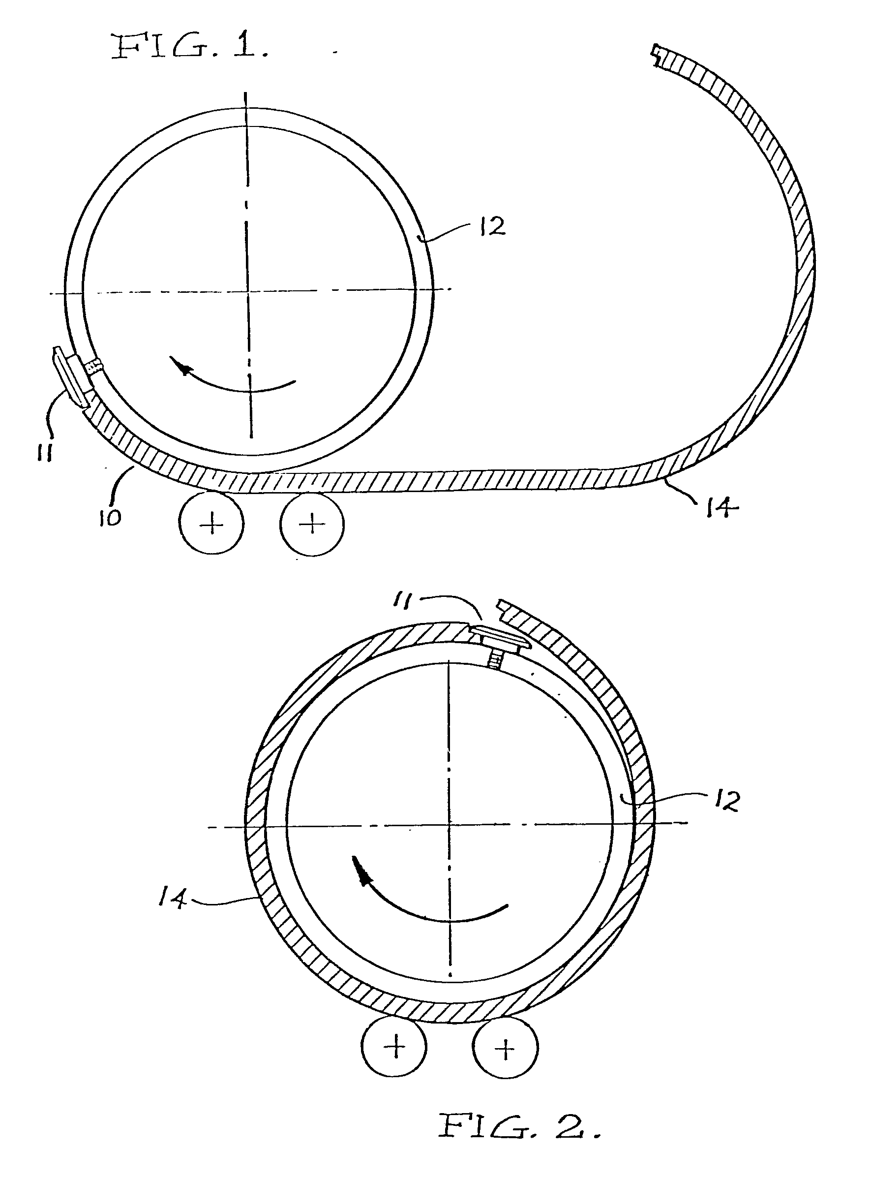
Figure 1 is a partial sectional view of a gripper and plate;
Figure 2 is an end elevation of a mandrel with a near completed bending operation.
[0007] Figure 1 shows the positioning of a recessed flat plate 10 onto the gripper 11. The
mandrel- 12 is rotatably mounted on a horizontal axis. The mounting means for the
mandrel is mounted for controlled up and down movement under the influence of preferably
hydraulic power cylinders (not shown). Upon location of the plate adjacent to the
gripper 11, the mandrel 12 is moved down in the direction of arrow A to engage the
pressure roll 14 and is rotated towards the plate edge to force the edge of the plate
home into full engagement with the gripper means 11. The effect of moving mandrel
12 is to ensure surface to surface contact along the entire length of the plate with
the mandrel as the plate edge is being forced into the gripper. This ensures that
any irregularity in the plate edge is removed as the edge is forced into the gripper.
After engagement of the plate the mandrel is rotated in counter clockwise direction
to achieve bending of the plate in accordance with the herein mentioned patent; this
is achieved by maintaining contact with pressure rollers 14.
[0008] A similar procedure is followed in stage 2 of the bending operation when gripping
the opposite edge of the plate prior to bending the uncurved half of the plate.
[0009] The notching or recessing of the plate is necessary where its thickness to diameter
ratio exceeds a maximum limit. The gripper 11 must be radially dimensioned within
limits to enable acceptance of the plate edge because of the possibility of fouling
with the curved plate during the final stages of curving. Thus a recess is machined
in the edges of the plate so that the gripper can be accommodated within the total
plate thickness relative to the recessed plate edge and enables curving of thick plates
on relatively small diameter mandrels. The reduced thickness of the recessed plate
edge enables curving of thick plates on relativelytsmall diameter mandrels. Thus it
is possible for the D ratio (where D is the pipe diameter and t plate thickness) to
improve from approximately 30 to about 25 on structural grade steels and from about
20 to about 16 on high strength steels.
1. In a method of rolling plate to form a curved article including the steps of engaging
one edge of a length of plate between a mandrel and gripping means on the mandrel,
turning the mandrel to curve the plate, the improvement comprising the step of recessing
or notching the edge of the plate to reduce the dimension of the edge to be gripped
by said gripping means such that the combined dimension of the notched edge and the
gripping means is substantially the same as or less than--the plate thickness.
2. The method as claimed in claim 1 in which the plate is curved to a substantially
cylindrical shape.
3. In a method of rolling plate to form a cylindrical article including the steps
of engaging one edge of a length of plate between a mandrel and gripping means on
the mandrel to form a substantially semi-circular curve by turning the mandrel to
curve the plate, placing the opposite edge of the plate in gripping means and turning
the mandrel to form a substantially cylindrical article, the improvement comprising
the step of reducing the plate thickness at least on said opposite edge of the plate
such that the radial dimension of said last mentioned gripper means is substantially
the same as or less than the plate thickness.
4. A plate rolling apparatus as claimed in claim 1 or 2 in which the gripper means
for gripping said plate edge includes a gripper capable of accepting a plate edge
having a reduced dimension of one half the plate thickness.