| (19) |
 |
|
(11) |
EP 0 051 552 B1 |
| (12) |
EUROPEAN PATENT SPECIFICATION |
| (45) |
Mention of the grant of the patent: |
|
07.01.1987 Bulletin 1987/02 |
| (22) |
Date of filing: 09.10.1981 |
|
| (51) |
International Patent Classification (IPC)4: B29D 30/24 |
|
| (54) |
Tire building machine drum
Reifenaufbautrommel
Tambour de confection de pneus
|
| (84) |
Designated Contracting States: |
|
DE FR GB IT LU |
| (30) |
Priority: |
05.11.1980 US 204322
|
| (43) |
Date of publication of application: |
|
12.05.1982 Bulletin 1982/19 |
| (71) |
Applicant: THE GOODYEAR TIRE & RUBBER COMPANY |
|
Akron, Ohio 44316-0001 (US) |
|
| (72) |
Inventors: |
|
- Felten, Gilbert Alphonse
L-1148 Luxembourg (LU)
- Stalter, Joseph Francis Jr.
Mogadore
Ohio 44260 (US)
|
| (74) |
Representative: Weyland, J.J. Pierre |
|
Goodyear Technical Center-Luxembourg
7750 Colmar-Berg
7750 Colmar-Berg (LU) |
|
| |
|
| Note: Within nine months from the publication of the mention of the grant of the European
patent, any person may give notice to the European Patent Office of opposition to
the European patent
granted. Notice of opposition shall be filed in a written reasoned statement. It shall
not be deemed to
have been filed until the opposition fee has been paid. (Art. 99(1) European Patent
Convention).
|
[0001] This invention relates to a known drum for tire building machines according to the
preamble of claim 1 and especially to a positive crown drum which has flanged shoulder
rings and a stretchable bladder. The drum is expandable and contractible to facilitate
placing a tire band over the drum and removal of the built and shaped tire from the
drum. The shoulder ring flanges are needed for seating of the beads; however, when
the segments are retracted the flanges have made it difficult to contract the drum
into a compact space. In the past, half of the segments of the drum have been first
moved axially of the drum and then retracted to prevent interference with the flanges
of the other segments. Separate additional actuating apparatus was required for moving
the first group of segments axially and this required additional controls as well
as air seals to prevent leakage of air from within the bladder.
[0002] Another problem has been maintaining alignment of the segments as they are retracted
and extended so that they will occupy a minimum space in the contracted condition
of the drum and fit together to make a continuous cylindrical shoulder of the drum
in the expanded condition.
[0003] The present invention is directed to a drum wherein a primary set of circumferentially
spaced shoulder ring segments are moved radially during expansion and contraction
of the drum. A secondary set of segments is positioned between the segments of the
primary set and the secondary segments are axially displaced from the primary segments
during contraction of the drum. The primary set of segments are mounted on radially
movable pistons and the secondary set of segments are mounted on pistons movable .in
cylinders inclined axially away from the ends of the drum. The pistons carrying both
sets of segments are prevented from rotating relative to the cylinders and thereby
maintain the segments in alignment for nesting in the contracted condition of the
drum. The extension of the pistons is also limited so that the segment will fit in
a continuous ring in the expanded condition.
[0004] In accordance with the invention, a contractible tire building drum is provided,
rotatable about a drum axis and having a pair of shoulder rings connected by an inflatable
bladder with each of the shoulder rings comprising a primary set of primary segments,
a secondary set of secondary segments, the primary segments being positioned circumferentially
between the secondary segments to form a segmental, generally cylindrical ring member
having a radially inwardly extending flanged portion at its outer edge, first means
for retracting and extending the primary segments between an expanded generally cylindrical
condition and a contracted nested condition of the ring member, second means for retracting
and extending the secondary segments between the cylindrical condition and the nested
condition of the ring member characterized by guide means for displacing the secondary
segments in an axial inward direction during contraction of the ring member so that
the secondary segments are axially offset from the primary segments in the contracted
condition of the ring member and the flanged portions of the primary segments overlap
the flanged portions of the secondary segments in the contracted nested condition
of the ring member.
[0005] To the accomplishment of the foregoing and related end, the invention, then, comprises
the features hereinafter fully described and particularly pointed out in the claims,
the following description and the annexed drawings setting forth in detail a certain
illustrative embodiment of the invention, this being indicative, however, of but one
of the various ways in which the principles of the invention may be employed.
[0006] In the annexed drawings:
Fig. 1 is a fragmentary side elevational view partly in section and taken along line
1-1 of Fig. 2 of a preferred form of tire building machine drum showing the left-hand
side of the drum in the contracted condition and the right-hand side of the drum in
the expanded condition. The section for the upper half of the drum is taken along
a plane through the axes of two corresponding primary segment cylinders and the section
for the lower half of the drum is taken along a plane through the axes of two corresponding
secondary segment cylinders.
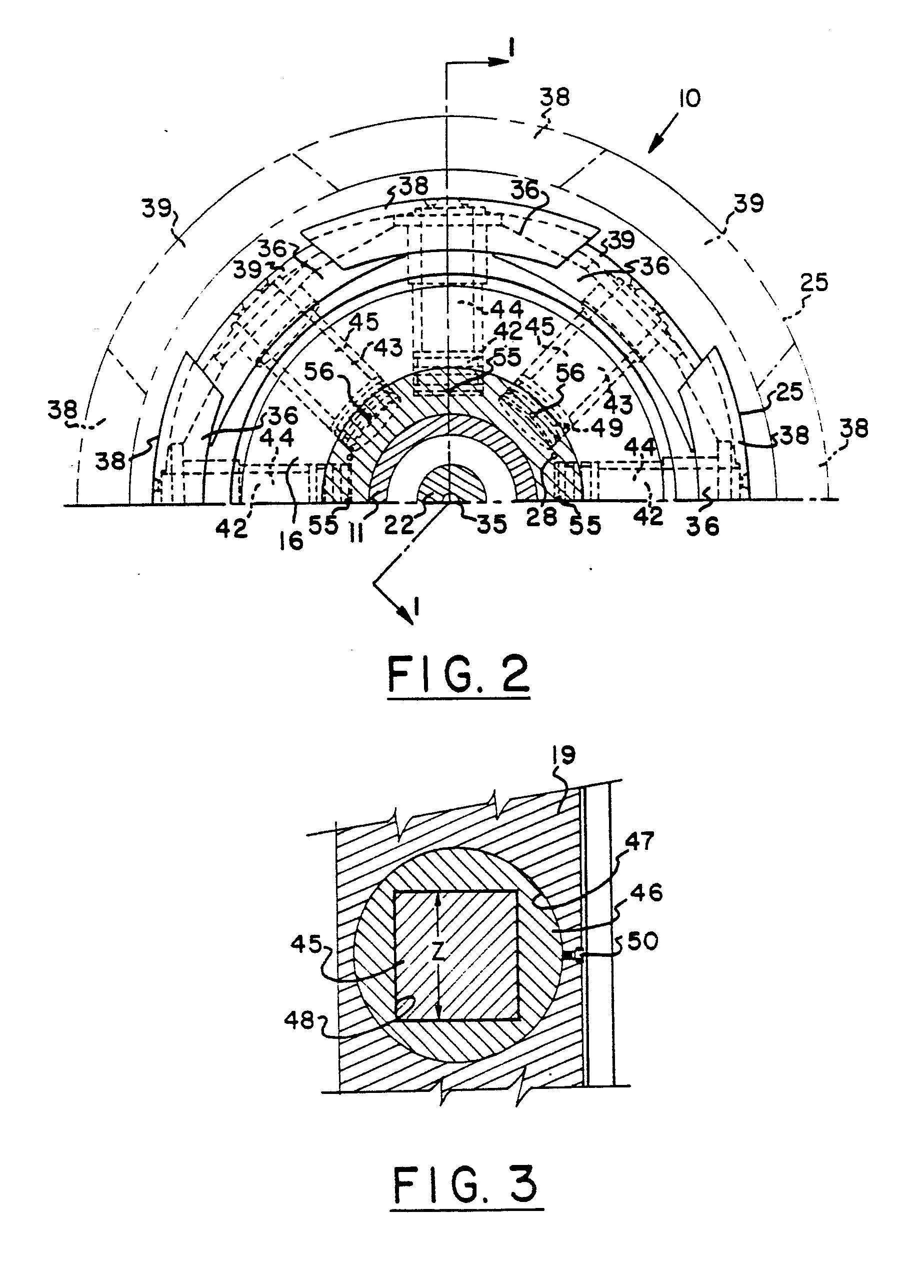
Fig. 2 is an enlarged fragmentary end elevation of the upper half of the drum with
the bladder removed, taken along line 2-2 of Fig. 1 showing the shoulder segments
with the flanges overlapping in the retracted position in full lines and showing the
shoulder segments joined in ring shape in the expanded condition in phantom lines.
Fig. 3 is a further enlarged fragmentary sectional view taken along the line 3-3 of
Fig. 1 showing the square opening in one of the bushings and the square cross section
of the corresponding matching piston rod for maintaining alignment of the shoulder
segments.
[0007] Referring to Fig. 1, a contractible tire building drum 10 which is especially adapted
for building radial truck tires is shown. The drum 10 is rotatable about a drum axis
A-A on a hollow shaft 11 extending from a flanged end 12 at the inboard end to a spindle
end cap 13 at the outboard end. The flanged end 12 is bolted to a drive shaft (not
shown) and the spindle end cap 13 is adapted to engage a spindle on an outboard carriage
assembly (not shown). The inboard and outboard ends of the drum 10 carry double bladder
turnup assemblies 14 and 15 including expandable bead locks of a construction familiar
to those skilled in the art.
[0008] Between the double bladder turnup assemblies 14 and 15 are portions of a left-hand
hub 16 and a right-hand hub 17 which also extend within the double bladder turnup
assemblies and are axially slidable on the shaft 11. The left-hand hub 16 is supported
in sealing engagement with the shaft 11 by a bushing 18 and by at least one other
bushing (not shown) inboard of bushing 18. The right-hand hub 17 is supported by a
bushing 19 in sealing engagement with the shaft 11 and by at least one other bushing
(not shown) outboard of bushing 19.
[0009] A screw 22 is rotatably mounted within the hollow shaft 11 and has left screw threads
23 and right screw threads 24 engageable with threaded collars (not shown) connected
to the left-hand hub 16 and right-hand hub 17, respectively. The left screw threads
23 and right screw threads 24 are of a different hand and therefore upon rotation
of the screw 22 move the left-hand hub 16 and right-hand hub 17 together or apart.
[0010] The drum 10 has a pair of shoulder rings 25 and 26 shown in Figs. 1 and 2. An inflatable
bladder 27 extends over the shoulder rings 25 and 26 and is clamped between the double
bladder turnup assemblies 14 and 15 and the hubs 16 and 17 in sealing engagement.
The bladder 27 may be of resilient material such as rubber and may be reinforced by
suitable reinforcing fabric such as a double knit textile material for limiting the
expansion of the bladder. An inner supply passage 28 in the left-hand hub 16 may be
connected to an air hose 29 which is in communication with a suitable air pressure
supply source and controls for inflating and deflating the bladder 27.
[0011] Tubing 32 between a valve core housing 33 in the bladder 27 and a rotary union 34
is in communication with a central passage 35 leading to the left end of the screw
22 which is connected to a source of air pressure and controls for inflating the tire
after it is built on the bladder 27 so that a belt and tread may be applied in the
toroidal shape of the tire.
[0012] Because the shoulder ring 25 and its actuating mechanism is a reverse copy of the
shoulder ring 26 and its actuating mechanism, the following description of the shoulder
ring 25 will also apply to the description of shoulder ring 26. Similar parts for
shoulder ring 26 and its actuating mechanism will be identified on the drawings by
the suffix "a" such as flanged portions 36 and 36a at the outboard side of shoulder
rings 25 and 26, respectively.
[0013] Referring to Fig. 2, the shoulder ring 25 is shown in phantom lines in the expanded,
generally cylindrical, condition and in full lines in the contracted, nested condition.
The shoulder ring 25 has a primary set of primary segments 38 and a secondary set
of secondary segments 39. The primary segments 38 are positioned circumferentially
between the secondary segments 39 to form a segmental, generally cylindrical, ring
member. In this particular embodiment there are four primary segments 38 and four
secondary segments 39. As shown in Figs. 1 and 2, the primary segments 38 are supported
and moved in a radial direction by primary piston and cylinder assemblies 42 spaced
at ninety degree intervals around the left-hand hub 16. The cylinder axes for the
primary piston and cylinder assemblies 42 extend radially outward from the axis A-A
of the drum 10 and are positioned in a plane P-P generally perpendicular to the axis
A-A.
[0014] The secondary segments 39 are supported and moved in a radial direction at an angle
to the plane P-P by secondary piston and cylinder assemblies 43 positioned at ninety
degree intervals around the left-hand hub 16 and spaced at forty-five degree intervals
from the primary piston and cylinder assemblies 42. The secondary piston and cylinder
assemblies 43 serve as guide means for the secondary segments 39 to restrict the movement
of the secondary segments to directions diverging from the direction of movement of
the primary segments 38 during the retraction of the secondary segments.
[0015] As shown in Fig. 1, the cylinder axis S-S of one of the secondary piston and cylinder
assemblies 43 is at an angle X to the plane P-P perpendicular to the axis A-A of the
drum 10 and this angle may be in the range of from about two degrees to ten degrees.
In the particular embodiment shown, the angle X is about seven and one-half degrees.
At the angle X, the secondary segments 39 are axially offset from the primary segments
38 in the contracted condition of the shoulder ring 25 in an amount Y which is equal
to or greater than the flange thickness of the flanged portion 36. With this construction,
segments of the flanged portion 36 on the primary segments 38 overlap segments of
the flanged portion on the secondary segments 39 in the nested condition so that the
shoulder ring 25 will have a reduced diameter and facilitate mounting of a tire band
over the drum 10 and removing a finished tire from the drum.
[0016] The primary segments 38 are fastened to primary piston rods 44 by suitable fasteners
such as rivets or screws and the secondary segments 39 are fastened to secondary piston
rods 45 by suitable fasteners such as rivets or screws. As shown in Fig. 3, the secondary
piston rods 45 are slidably mounted in bushings 46 which are non- rotatably fastened
to cylinders 47 of the secondary piston and cylinder assemblies 43 in the hubs 16
and 17. The piston rods 45 are noncylindrical for sliding engagement with corresponding
noncylindrical openings 48 in the bushings 46 to maintain the segments 39 in the desired
position without rotation during extension and retraction. In this particular embodiment
as shown in Fig. 3, the piston rods 45 are square in cross section and the openings
48 in the bushings 46 have a corresponding matching square cross section.
[0017] The bushings 46 are fastened in the cylinders 47 as by screws 50 to limit the extension
of the secondary segments 39. As shown in the drawings, pistons 49 of the secondary
piston and cylinder assemblies 43 have a greater diameter than the minimum cross-sectional
dimension Z of the openings 48 in the bushings 46 and this serves to locate the secondary
segments 39 in the shoulder ring 25 at the desired diameter in the expanded condition.
[0018] The primary piston and cylinder assemblies 42 also have bushings 52 of a similar
construction to the bushings 46 and the piston rods 44 have square cross sections
for sliding engagement with corresponding matching square openings in the bushings
52. Also pistons 53 of the primary piston and cylinder assemblies 42 have diameters
which are greater than the minimum cross-sectional dimension of the openings in the
bushings 52 as described hereinabove for the secondary piston and cylinder assemblies
43 so as to locate the primary segments 38 in the shoulder rings 25 at the desired
diameter in the expanded condition.
[0019] The piston and cylinder assemblies 42 and 43 are actuated by air or vacuum and are
in communication with a suitable source of vacuum and air supply. Suitable controls
are provided for operating the primary piston and cylinder assemblies 42 separately
from the secondary piston and cylinder assemblies 43. In this embodiment, the vacuum
is applied to the secondary piston and cylinder assemblies 43 to move the secondary
segments 39 to the retracted position as shown in Fig. 2 and then vacuum is applied
to the primary piston and cylinder assemblies 42 to move them to the retracted positions
shown in Figs. 1 and 2.
[0020] In operation of the tire building drum 10 at the beginning of the tire building process,
the primary and secondary piston and cylinder assemblies 42 and 43 are in the retracted
position as shown in the left side of Fig. 1 with the inflatable bladder 27 in the
relaxed minimum diameter position. The outboard carriage assembly is spaced from the
spindle end cap 13 and beads are placed over the bead rings and the band is placed
on the collapsed drum and centered. The outboard carriage is then moved into the support
position and engages the spindle end cap 13. At this time the operator may lift the
band and actuate suitable controls to communicate air under pressure to the primary
and secondary piston and cylinder assemblies 42 and 43 to extend the primary segments
38 and the secondary segments 39 to the expanded position of the drum 10, shown in
Fig. 1.
[0021] Air and vacuum is communicated to the cylinders of the primary piston and cylinder
assemblies 42 through passages 55 in the hub 16. Air and vacuum is communicated to
the cylinders of the secondary piston and cylinder assemblies 43 through passages
56 in the hub 16. Suitable controls are provided for communicating vacuum and air
pressure to the cylinders of the primary and secondary piston and cylinder assemblies
42 and 43 so that the expansion and contraction of the primary and secondary segments
38 and 39 may be in sequence. The extension and retraction of the primary segments
38 is done simultaneously and the retraction and extension of the secondary segments
is done simultaneously.
[0022] During the building operation, the inflatable bladder 27 is extended from the position
shown in dot-dash lines in the right-hand side of Fig. 1 to the position shown in
full lines by inflating the bladder through passage 28. This provides a surface for
supporting the tire band during building of the tire carcass. When the tire carcass
has been built on the drum 10 the hubs 16 and 17 are moved together by rotation of
the screw 22 and the tire is inflated by air pressure communicated to the tire through
passage 35 in the screw and through the tubing 32 and valve core housing 33. The tire
carcass inflates into end bells (not shown) to form the shaped tire. At this time
the breakers and tread are applied in sequence to the carcass over the end bells to
complete the tire. To remove the tire the air pressure is released from the tire and
vacuum is applied to the cylinders of the secondary piston and cylinder assemblies
43 moving the secondary segments 39 to the position shown at the left side of Fig.
1. Then the vacuum is applied to the primary piston and cylinder assemblies 42 moving
the primary segments 38 to the position shown in the left-hand side of Fig. 1 and
in full lines in Fig. 2. The tire may then be removed from the tire building drum
10.
1. A contractible tire building drum (10) rotatable about a drum axis (A-A) and having
a pair of shoulder rings (25, 26) connected by an inflatable bladder (27) with each
of said shoulder rings (25, 26) comprising a primary set of primary segments (38),
a secondary set of secondary segments (29), said primary segments (38) being positioned
circumferentially between said second segments (39) to form a segmental, generally
cylindrical ring member having a radially inwardly extending flanged portion (12)
at its outer edge, first means (42) for retracting and extending said primary segments
(38) between an expanded generally cylindrical condition and a contracted nested condition
of said ring member, second means (43) for retracting and extending said secondary
segments (39) between said cylindrical condition and said nested condition of said
ring member, characterized by guide means (47) for displacing said secondary segments
(39) in an axial inward direction during contraction of said ring member so that said
secondary segments (39) are axially offset from said primary segments (38) in the
contracted condition of said ring member and the flanged portions (36) of said primary
segments (38) overlap the flanged portions of said secondary segments (39) in said
contracted nested condition of said ring member.
2. A tire building drum (10) in accordance with claim 1 characterized in that said
secondary segments (39) are displaced axially during retraction and said primary segments
(38) are movable in a direction perpendicular to said drum axis (A-A).
3. A tire building drum (10) in accordance with claim 1 characterized in that said
guide means (47) limits the movement of said secondary segments (39) to paths diverging
from paths of said primary segments (38) during retraction of said secondary segments
(39).
4. A tire building drum (10) in accordance with claim 1 characterized in that said
second means (43) for retracting and extending said secondary segments (39) is operable
before said first means (42) so that said secondary segments (39) are moved first
to the retracted position and then said primary segments (38) are moved to the retracted
position for nesting of said primary segments (38) in radially overlapping relationship
with said secondary segments (39).
5. A tire building drum (10) in accordance with claim 2 characterized in that the
retracting movements of said secondary segments (39) are in paths at an angle (X)
to said direction perpendicular to said axis (A-A).
6. A tire building drum (10) in accordance with claim 1 characterized in that said
first and second means (42, 43) for retracting and extending said segments (38, 39)
are piston cylinders assemblies (42, 43) with cylinder axes (S-S) of said assemblies
(42) for said first means extending radially outward from said axis (A-A) of the drum
(10) and being positioned in a plane (P-P) generally perpendicular to said axis (A-A),
and cylinder axes (S-S) of said assemblies (43) for said second means being at an
angle (X) to said plane (P-P) containing said cylinder axes of said first means (42).
7. A tire building drum (10) in accordance with claim 6 characterized in that said
angle (X) is in the range of from about 2 degrees to 10 degrees.
8. A tire building drum (10) in accordance with claim 1 characterized in that said
flanged portion (12) has a flange thickness and said secondary segments (39) are axially
offset from said primary segments (38) in the contracted condition of said ring member
(25, 26) in an amount equal to or greater than said flange thickness.
9. A tire building drum (10) in accordance with claim 6 characterized in that said
segments (38, 39) are mounted on piston rods (44, 44a) of said piston-cylinder assemblies
(42, 43) and said piston rods (44, 44a) are slidably movable in bushing members (46,
46a) in said cylinders of said first and second means (42, 43) for retracting and
extending said segments (38, 39), said piston rods (44, 44a) being noncylindrical
for sliding engagement with corresponding matching noncylindrical openings (48) in
said bushings (46, 46a) to maintain said segments (38, 39) in the desired position
without rotation during extension and retraction of said segments (38, 39).
10. A tire building drum (10) in accordance with claim 9 characterized in that said
cross sections of said piston rods (44, 44a) are square and said openings in said
bushings (46, 46a) have a corresponding matching square cross section.
11. A tire building drum (10) in accordance with claim 10 characterized in that said
piston-cylinder assemblies (42, 43) comprise pistons (49, 53) having a greater diameter
than the minimum cross-sectional dimension of the openings (48) in said bushings (46,
46a) to limit the extension of said pistons (49, 53) in said cylinders (47) and locate
said segments (38, 39) radially in the ring (25, 26) of said drum (10) in the expanded
condition.
12. A tire building drum (10) in accordance with claim 1 characterized in that said
flanged portion (12) is at an outer edge of said drum (10) and said secondary segments
(39) are axially offset from said primary segments (38) in a direction away from said
outer edge of said drum (10).
13. A tire building drum (10) in accordance with claim 12 characterized in that said
first means (42) for retracting and extending said primary segments (38) of said shoulder
ring member of each of said shoulder rings (25, 26) are operated simultaneously and
said second means (43) for retracting and extending said secondary segments (39) of
said shoulder ring member of each of said shoulder rings (25, 26) are operated simultaneously
for simultaneous expansion and contraction of said shoulder rings (25, 26) at each
end of said drum (10).
14. A tire building drum (10) in accordance with claim 13 characterized by including
means to inflate said bladder (27) to provide a surface for supporting a tire band
during building of the tire carcass, means (50) for axially moving said shoulder rings
(25, 26) together and means (29) for inflating a tire on said drum (10) to a toric
shape for applying a belt and tread.
1. Zusammenziehbare, um eine Trommelachse (A-A) rotierende Reifenaufbautrommel (10)
mit einem Paar von Schulterringen (25, 26), die über einen aufblasbaren Heizbalg (27)
verbunden sind, wobei jeder der Schulterringe (25, 26) einen ersten Satz von primären
Segmenten (38) und einen zweiten Satz von sekundären Segmenten (39) aufweist, wobei
die primären Segmente (38) in Umfangsrichtung zwischen den sekundären Segmenten (39)
angeordnet sind, um ein aus Segmenten bestehendes, im wesentlichen zylindrisches Ringelement
mit einem radial innen sich erstreckenden Flanschabschnitt (12) an der Außenkante
zu bilden, mit einer ersten Einrichtung (42) zum Einziehen und Ausfahren der primären
Segmente (38) zwischen einem expandierten, im wesentlichen zylindrischen Zustand und
einem zusammengezogenen eingefahrenen Zustand des Ringelementes, mit einer zweiten
Einrichtung (43) zum Einziehen und Ausfahren der sekundären segmente (39) zwischen
dem zylindrischen Zustand und dem eingefahrenen Zustand des Ringelementes, gekennzeichnet
durch eine Führungseinrichtung (47) zum Verschieben der sekundären Segmente (39) in
einer axial nach innen verlaufenden Richtung während des Zusammenziehens des Ringelementes,
so daß die sekundären Segmente (39) in dem zusammengezogenen Zustand des Ringelementes
axial versetzt von den primären Segmenten (38) sind und die Flanschabschnitte (36)
der primären Segmente (38) die Flanschabschnitte der sekundären Segmente (39) in dem
zusammengezogenen, eingefahrenen Zustand des Ringelementes überlappen.
2. Reifenaufbautrommel (10) nach Anspruch 1, dadurch gekennzeichnet, daß die sekundären
Segmente (39) während des Einziehens axial verschoben werden, und daß die primären
Segmente (38) in einer Richtung senkrecht zu der Trommelachse (A-A) verschiebbar sind.
3. Reifenaufbautrommel (10) nach Anspruch 1, dadurch gekennzeichnet, daß die Führungseinrichtung
(47) die Bewegung der sekundären Segmente (39) auf Bahnen beschränkt, die von Bahnen
der primären Segmente (38) während des Einziehens der sekundären Segmente (39) abweichen.
4. Reifenaufbautrommel (10) nach Anspruch 1, dadurch gekennzeichnet, daß die zweite
Einrichtung (43) zum Einziehen und Ausfahren der sekundären Segmente (39) vor der
ersten Einrichtung (42) betätigbar ist, so daß die sekundären Segmente (39) zuerst
in die eingezogene Stellung und dann die primären Segmente (38) in die eingezogene
Stellung bewegt werden, um die primären Segmente (38) in radial überlappenden Stellungen
mit den sekundären Segmenten (39) ineinander zu schachteln.
5. Reifenaufbautrommel (10) nach Anspruch 2, dadurch gekennzeichnet, daß die Einziehbewegungen
der sekundären Segmente (39) auf Bahnen unter einem Winkel (X) zu der Richtung senkrecht
zu der Achse (A-A) erfolgen.
6. Reifenaufbautrommel (10) nach Anspruch 1, dadurch gekennzeichnet, daß die erste
und die zweite Einrichtung (42, 43) zum Einziehen und Ausfahren der Segmente (38,
39) Kolbenzylinderanordnungen (42, 43) sind, daß die Zylinderachsen (S-S) der Anordnungen
(42) für die erste Einrichtung sich radial nach außen von der Achse (A-A) der Trommel
(10) erstrecken und in einer Ebene (P-P) im wesentlichen senkrecht zu der Achse (A-A)
angeordnet sind, und daß die Zylinderachsen (S-S) der Anordnungen (43) der zweiten
Einrichtung unter einem Winkel (X) zu der Ebene (P-P) angeordnet sind, in welcher
die Zylinderachsen der ersten Einrichtung (42) vorgesehen sind.
7. Reifenaufbautrommel (10) nach Anspruch 6, dadurch gekennzeichnet, daß der Winkel
(X) im Bereich von etwa 2° bis 10° liegt.
8. Reifenaufbautrommel (10) nach Anspruch 1, dadurch gekennzeichnet, daß der Flanschabschnitt
(12) eine Flanschdicke aufweist und daß die sekundären Segmente (39) in Axialrichtung
um einen Betrag versetzt von den primären Segmenten (38) in dem zusammengezogenen
Zustand des Ringelementes (25, 26) sind, der gleich oder größer als die Flanschdicke
ist.
9. Reifenaufbautrommel (10) nach Anspruch 6, dadurch gekennzeichnet, daß die Segmente
(38, 39) auf Kolbenstangen (44, 44a) der Kolbenzylinderanordnungen (42, 43) befestigt
sind, daß die Kolbenstangen (44,44a) verschiebbar in Buchsen (46, 46a) in den Zylindern
der ersten und zweiten Einrichtung (42, 43) zum Einziehen und Ausfahren der Segmente
sind, und daß die Kolbenstangen (44, 44a) nicht zylindrisch ausgebildet sind für einen
Gleiteingriff mit entsprechend ausgebildeten nicht zylindrischen Öffnungen (48) in
den Buchsen (46, 46a), um die Segmente (38, 39) während des Ausfahrens und des Einziehens
der Segmente (38, 39) ohne Rotation in der gewünschten Stellung zu halten.
10. Reifenaufbautrommel (10) nach Anspruch 9, dadurch gekennzeichnet, daß die Querschnittsflächen
der Kolbenstangen (44, 44a) rechteckig sind, und daß die Öffnungen in den Buchsen
(46, 46a) einen entsprechend angepaßten rechteckigen Querschnitt aufweisen.
11. Reifenaufbautrommel (10) nach Anspruch 10, dadurch gekennzeichnet, daß die Kolbenzylinderanordnungen
(42, 43) Kolben (49, 53) mit einem größeren Durchmesser als der minimalen Querschnittsabmessung
der Öffnungen (48) in den Buchsen (46, 46a) aufweisen, um das Ausfahren der Kolben
(49, 53) in den Zylindern (47) zu begrenzen und die Segmente (38, 39) in Radialrichtung
in dem Ring (25, 26) der Trommel (10) in dem expandierten Zustand zu festzulegen.
12. Reifenaufbautrommel (10) nach Anspruch 1, dadurch gekennzeichnet, daß der Flanschabschnitt
(12) an einer Außenkante der Trommel (10) angeordnet ist, und daß die sekundären Segmente
(39) in Axialrichtung versetzt von den primären Segmenten (38) in einer Richtung weg
von der Außenkante der Trommel (10) sind.
13. Reifenaufbautrommel (10) nach Anspruch 12, dadurch gekennzeichnet, daß die erste
Einrichtung (42) zum Einziehen und Ausfahren der primären Segmente (38) des Schulterringelementes
jedes der Schulterringe (25, 26) gleichzeitig betätigt wird, und daß die zweite Einrichtung
(43) zum Einziehen und Ausfahren der sekundären Segmente (39) des Schulterringelementes
jedes der Schulterringe (25, 26) gleichzeitig betätigt wird zum gleichzeitigen Expandieren
und Zusammenziehen der Schulterringe (25, 26) an jedem Ende der Trommel (10).
14. Reifenaufbautrommel (10) nach Anspruch 13, gekennzeichnet durch eine Einrichtung
zum Aufblasen des Heizbalges (27) zur Herstellung einer Oberfläche zum Abstützen eines
Reifenbandes während des Aufbaus der Reifenkarkasse, durch eine Einrichtung (50),
um die Schulterringe (25, 26) zusammen axial zu verschieben, und durch eine Einrichtung
(29) zum Aufblasen eines Reifens aus der Trommel (10) in eine Torusform zum Anbringen
eines Gürtels und einer Lauffläche.
1. Tambour de confection de bandages pneumatiques (10) susceptible de contraction,
pouvant tourner autour d'un axe (A-A) et comportant deux anneaux d'épaulements (25,
26) reliés par une vessie gonflable (27), chacun de ces anneaux d'épaulements (25,
26) comprenant un jeu de segments primaires (38), un jeu de segments secondaires (39),
les segments primaires (38) étant disposés circonférentiellement entre les segments
secondaires (39) en vue de former un organe annulaire segmentaire généralement cylindrique
comportant un rebord s'étendant radialement vers l'intérieur (12) à son bord extérieur,
un premier moyen (42) destiné à rétracter et à déployer les segments primaires (38)
entre une position déployée généralement cylindrique et une position contractée d'emboîtement
de l'organe annulaire, un second moyen (43) destiné à rétracter et à déployer les
segments secondaires (39) entre la position cylindrique et la position d'emboîtement
de l'organe annulaire, caractérisé par un moyen de guidage (47) destiné à déplacer
les segments secondaires (39) vers l'intérieur dans une direction axiale au cours
de la contraction de l'organe annulaire, de telle sorte que les segments secondaires
(39) soient décalés axialement par rapport aux segments primaires (38) à l'état contracté
de l'organe annulaire et que les rebords (36) des segments primaires (38) chevauchent
les rebords des segments secondaires (39) à l'état contracté de emboîtement de l'organe
annulaire.
2. Tambour de confection de bandages penuma- tiques (10) selon la revendication 1,
caractérisé en ce que les segments secondaires (39) sont déplacés axialement au cours
de la rétraction, tandis que les segments primaires (38) peuvent se déplacer dans
une direction perpendiculaire à l'axe du tambour (A-A).
3. Tambour de confection de bandages penuma- tiques (10) selon la revendication 1,
caractérisé en ce que les moyen de guidage (47) limite le mouvement des segments secondaires
(39) à des parcours divergeant par rapport aux parcours des segments primaires (38)
au cours de la rétraction des segments secondaires (39).
4. Tambour de confection de bandages pneumatiques (10) selon la revendication 1, caractérisé
en ce que le second moyen (43) destiné à rétracter et à déployer les segments secondaires
(39) peut fonc- tionnner avant le premier moyen (42), de telle sorte que les segments
secondaires (39) soient tout d'abord déplacés dans la position rétractée, après quoi
les segments primaires (38) sont déplacés dans la position rétractée pour l'emboîtement
des segments primaires (38) dans une relation de chevauchement radial avec les segments
secondaires (39).
5. Tambour de confection de bandages pneumatiques (10) selon la revendication 2, caractérisé
en ce que les mouvements de rétraction des segments secondaires (39) ont lieu dans
des parcours orientés sous un angle (X) par rapport à la direction perpendiculaire
à l'axe (A-A).
6. Tambour de confection de bandages pneumatiques (10) selon la revendication 1, caractérisé
en ce que les premier et second moyens (42, 43) destinés à rétracter et à déployer
les segments (38, 39) sont des assemblages à piston et cylindre (42,43), les axes
des cylindres (S-S) des assemblages (42) pour le premier moyen s'étendant radialement
vers l'extérieur à partir de l'axe (A-A) du tambour (10), tout en étant situés dans
un plan (P-P) généralement perpendiculaire à cet axe (A-A), tandis que les axes des
cylindres (S-S) des assemblages (43) pour le second moyen sont orientés sous un angle
(X) par rapport au plan (P-P) englobant les axes des cylindres du premier moyen (42).
7. Tambour de confection de bandages pneumatiques (10) selon la revendication 6, caractérisé
en ce que l'angle (X) se situe dans l'intervalle allant d'environ 2° à 10°.
8. Tambour de confection de bandages pneumatiques (10) selon la revendication 1, caractérisé
en ce que le rebord (12) a une certaine épaisseur, tandis que, à l'état contracté
de l'organe annulaire (25, 26), les segments secondaires (39) sont décalés axialement
par rapport aux segments primaires (38) d'une distance égale ou supérieure à l'épaisseur
du rebord.
9. Tambour de confection de bandages pneumatiques (10) selon la revendication 6, caractérisé
en ce que les segments (38, 39) sont montés sur des tiges de pistons (44,44a) des
assemblages à piston et cylindre (42, 43), les tiges de pistons (44, 44a) pouvant
coulisser dans des-douilles (46, 46a) formées dans les cylindres des premier et second
moyens (42, 43) pour la rétraction et l'extension des segments (38,39), les tiges
de pistons (44, 44a) étant non cylindriques pour venir s'engager par glissement dans
des ouvertures non cylindriques d'adaptation correspondantes (48) des douilles (46,
46a) afin de maintenir les segments (38, 39) dans la position désirée sans rotation
au cours de l'extension et de la rétraction des segments (38, 39).
10. Tambour de confection de bandages pneumatiques (10) selon la revendication 9,
caractérisé en ce que les sections transversales des tiges de pistons (44,44a) sont
carrées, tandis que les ouvertures ménagées dans les douilles (46,46a) ont une section
transversale carrée d'adaptation correspondante.
11. Tambour de confection de bandages pneumatiques (10) selon la revendication 10,
caractérisé en ce que les assemblages à piston et cylindre (42,43) comprennent des
pistons (49, 53) ayant un diamètre supérieur à la dimension de section transversale
minimum des ouvertures (48) ménagées dans les douilles (46, 46a) afin de limiter l'extension
des pistons (49, 53) dans les cylindres (47) et de localiser les segments (38, 39)
radialement dans l'anneau (25, 26) du tambour (10) à l'état expansé.
12. Tambour de confection de bandages pneumatiques (10) selon la revendication 1,
caractérisé en ce que le rebord (12) est localisé à un bord extérieur du tambour (10),
tandis que les segments secondaires (39) sont décalés axialement par rapport aux segments
primaires (38) dans une direction s'éloignant du bord extérieur précité du tambour
(10).
13. Tambour de confection de bandages pneumatiques (10) selon la revendication 12,
caractérisé en ce que les premiers moyens (42) destinés à rétracter et à déployer
les segments primaires (38) de l'organe annulaire d'épaulement de chacun des anneaux
d'épaulements (25, 26) sont actionnés simultanément, tandis que les seconds moyens
(43) destinés à rétracter et à déployer les segments secondaires (39) de l'organe
annulaire d'épaulement de chacun des anneaux d'épaulements (25, 26) sont également
actionnés simultanément en vue d'une expansion et d'une contraction simultanées des
anneaux d'épaulements (25, 26) à chaque extrémité du tambour (10).
14. Tambour de confection de bandages pneumatiques (10) selon la revendication 13,
caractérisé en ce qu'il comprend un moyen destiné à gonfler la vessie (27) en vue
de définir une surface pour supporter un bandage au cours de la confection de la carcasse
de bandage pneumatique, un moyen (50) destiné à déplacer axialement les anneaux d'épaulements
(25, 26) ensemble, ainsi qu'un moyen (29) destiné à gonfler un bandage penumatique
sur le tambour (10) pour lui donner une configuration toroïdale en vue de l'application
d'une ceinture et d'une bande de roulement.