| (19) |
 |
|
(11) |
EP 0 054 564 B1 |
| (12) |
EUROPEAN PATENT SPECIFICATION |
| (45) |
Mention of the grant of the patent: |
|
11.09.1985 Bulletin 1985/37 |
| (22) |
Date of filing: 25.06.1981 |
|
| (51) |
International Patent Classification (IPC)4: B65D 75/44
// B65B43/26 |
| (86) |
International application number: |
|
PCT/SE8100/187 |
| (87) |
International publication number: |
|
WO 8200/129 (21.01.1982 Gazette 1982/03) |
|
| (54) |
BLANK BELT
VERPACKUNGSZUSCHNITTSKETTE
FLANS EN BANDE
|
| (84) |
Designated Contracting States: |
|
AT CH DE FR GB LI LU NL SE |
| (30) |
Priority: |
30.06.1980 SE 8004829
30.06.1980 SE 8004830
06.10.1980 SE 8006976
|
| (43) |
Date of publication of application: |
|
30.06.1982 Bulletin 1982/26 |
| (71) |
Applicant: JOKER SYSTEM AKTIEBOLAG |
|
S-302 41 Halmstad (SE) |
|
| (72) |
Inventor: |
|
- JOSTLER, Jan
S-302 71 Halmstadt (SE)
|
| (74) |
Representative: Magnusson, Gustav |
|
MAGNUPATENT AB
P.O. Box 6207
200 11 Malmö 6
200 11 Malmö 6 (SE) |
|
| |
|
| Note: Within nine months from the publication of the mention of the grant of the European
patent, any person may give notice to the European Patent Office of opposition to
the European patent
granted. Notice of opposition shall be filed in a written reasoned statement. It shall
not be deemed to
have been filed until the opposition fee has been paid. (Art. 99(1) European Patent
Convention).
|
[0001] The present invention relates to a continuous flexible belt which displays two opposing
walls and longitudinal upper and lower edges and which incorporates a number of consecutively
arranged packaging blanks each with a bottom section at the aforementioned lower edge
and two bonding zones arranged transversely in relation to the longitudinal direction
of the belt which form the side closures of the packaging blank and a vertical slot
arranged between the bonding zones of two adjacent packaging blanks. The invention
also relates to a device for the filling of packaging blanks arranged in a continuous
flexible belt at a filling station with guide devices for opening the packaging blanks
as well as a method of filling and a method of opening such packaging blanks.
[0002] From the US Patent No. 3.559.874 there is known a continuous flexible belt displaying
the characteristics cited in the previous section. Furthermore, this belt, similarly
consisting of bag elements, is equipped with an internal longitudinal guide loop at
its upper edge, which communicates with the interior of the lower part of the bag
elements. The guide loop guides the bag elements on a mandrel arranged at a filling
station for the bag elements. In order to fill the bag elements a knife is mounted
atop the mandrel to cut the loop into two halves which are then separated sidewardly
with respect to each other by means of a pair of endless belts which carry the same
between them and a hopper situated in the middle. After filling the bag elements with
a product through the hopper, the two upper edges of the bag elements are united and
welded together, the remains of the guide loops are cut away and the individual bag
elements are separated from each other by tearing them loose from each other. The
arrangement is complicated. The velocity of feeding the bag elements must be coordinated
with the one of the pair of endless belts. During filling, the weight of the bag elements
is carried by forces acting at right angles to gravity, i.e. tangential forces acting
in the surface plane of the bag elements by means of the pair of endless belts pressing
towards each other. Also, during filling, the individual bag elements openings can
not be of for example square shape without causing high stresses in the material.
The separation of the remains of the guide loops necessitates the action of a cutting
element.
[0003] British Patent No. 1.509.639 describes a device for filling bag-shaped packagings
of fabric material which are advanced by means of two drive belts in engagement with
the outer sides of the packaging belt. The packagings are opened by means of a linkage
mechanism and attendant interacting guide devices. The device is complicated and does
not satisfy present-day demands for low costs of packaging different kinds of articles.
At all events, the device is not suitable for packaging in bags of plastic material
which are arranged in the form of a continuous belt.
[0004] One purpose of the present invention is to achieve a continuous belt of packaging
blanks which permits the use of a simplified device for filling the packaging blanks
in a simple and reliable manner, particularly packaging blanks of a plastic material.
[0005] This is achieved through the present invention in that the continuous belt incorporates
two principally opposing strip sections which extend in the longitudinal direction
of the belt at its aforementioned upper edge and which are demarcated from the packaging
blanks by means of a tear initiation, either formed in advance or in conjunction with
filling, in each wall arranged parallel to the aforementioned upper edge, whereby
each strip section is provided with a continuous suspension device for interacting
with the packaging blank opening guide devices arranged at a filling station for filling
the packaging blanks, in addition to which the belt is provided with a horizontal
slot in both walls either formed in advance or in conjunction with the filling operation,
arranged on either side of the aforementioned vertical slot and between the packaging
blanks and the suspension devices, whereby two adjacent horizontal slots are arranged
at a distance from each other.
[0006] The simplified device according to the invention is characterized in that the guide
devices consist of two adjacent guide bars arranged in the same plane for interacting
with the specified belt, whereby the guide bars display end sections which are situated
in the vicinity of each other and centre sections which are situated at a distance
from each other, these centre sections being arranged to separate the strip sections
of the belt from each other in conjunction with the opening of the packaging blanks,
whereby the desired material or object is placed in the packaging blanks.
[0007] The invention is described in greater detail in the following with reference to the
drawings, where
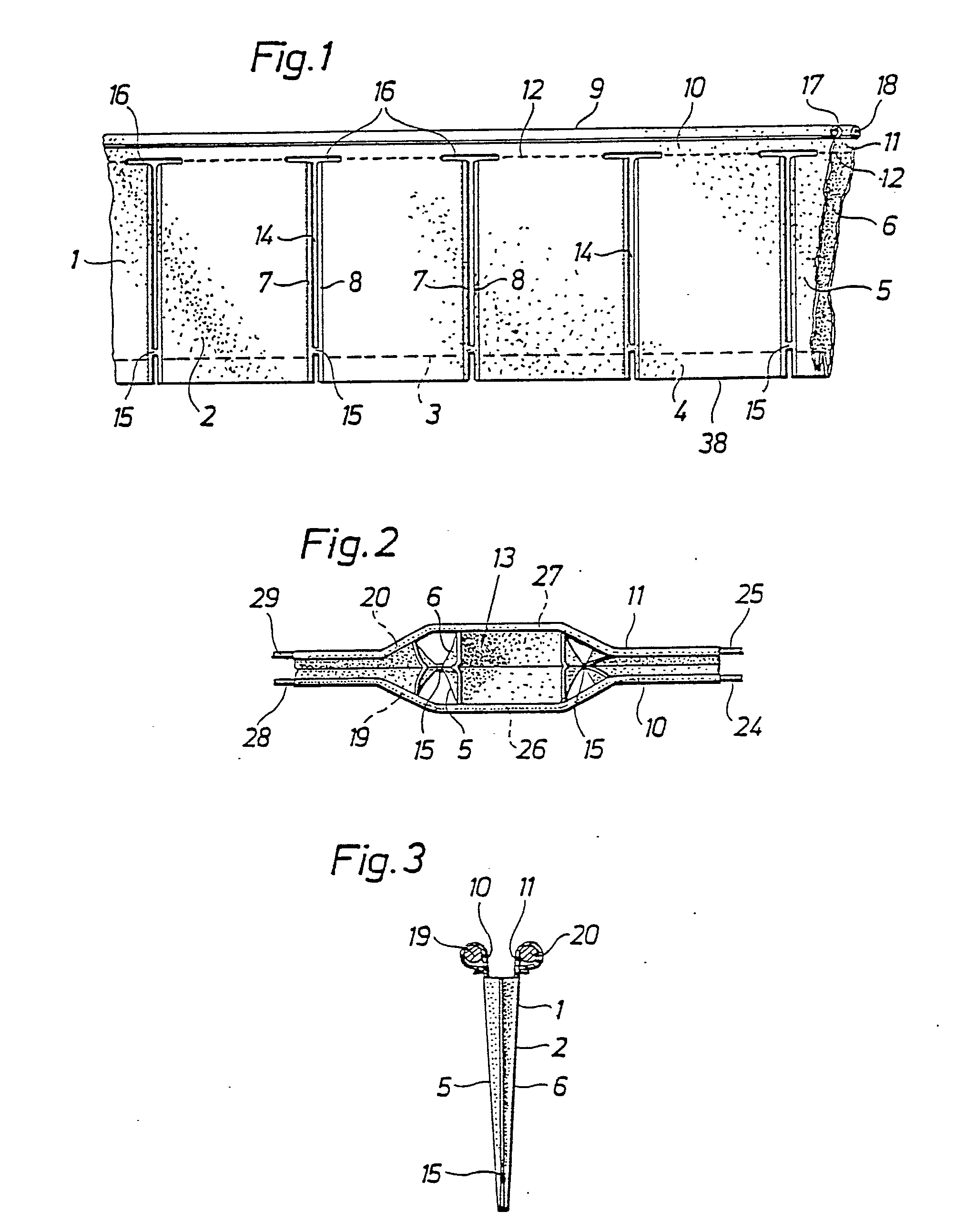
Fig. 1 shows a side view of a longitudinal cross-section of a continuous belt according
to the present invention,
Fig. 2 shows the belt as in Fig. 1 from above as it is advanced in a filling station,
Fig. 3 shows a cross-section through the belt at the line III-III in Fig. 4,
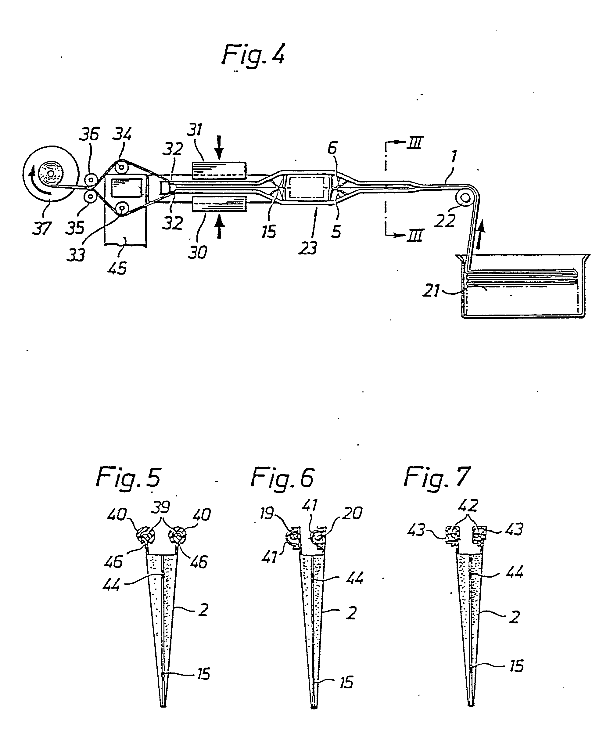
Fig. 4 shows schematically from above a device for handling a belt as in Fig. 1 from
magazine to finished packagings,
Fig. 5 shows a cross-section through a belt and guide devices according to another
version of the invention,
Fig. 6 shows a cross-section through a belt and guide devices according to a third
version of the invention, and where
Fig. 7 shows a cross-section through a belt and guide devices according to a fourth
version of the invention.
[0008] With reference to Fig. 1, a section of a continuous belt 1, which incorporate a number
of consecutively arranged packaging blanks 2, is shown. The belt has been formed by
folding a broader material belt along its centreline 3 to form the bottom section
4 of the packaging blanks, the said bottom section being folded inward as shown in
Fig. 1 during formation of the lower edge 38 of the belt. The opposing walls 5,6 obtained
through folding are joined to each other at regular intervals to form the bonding
zones 7, 8 which extend at right angles to the bottom section 4 of the packaging blanks.
The bonding zones, which can be formed by welding or gluing, or by any other suitable
means, demarcate each packaging blank laterally and extend from the bottom section
4 to an upper point which is situated at a predetermined distance from the upper edge
9 of the belt. The continuous belt also incorporates two longitudinal strip sections
10, 11 which comprise the upper areas of the wall formed through folding and which
are demarcated from the packaging blanks by a longitudinal perforation 12 in each
wall or other tear initiation which extends principally through the aforementioned
upper point in the bonding zones. The perforation 12 consequently demarcates the packaging
blanks at the top and defines the position of their openings 13.
[0009] Arranged in or between the bonding zones 7, 8 are vertical slots 14, whereby each
slot 14 may be interrupted by one or more bridges 15 which hold the packaging blanks
in a line after each other. Further, horizontal slots 16 are arranged in the area
for the boundary between the packaging blanks and the upper strip sections 10, 11,
i.e. according to the version disclosed in line with the horizontal perforation 12,
whereby these horizontal slots 16 are located adjacent to the vertical slots 14 and
joined to them in the form of a T. As will be evident from Fig. 1 two adjacent horizontal
slots 16 are arranged at a distance from each other. The slots are arranged in both
walls 5, 6 as also is the perforation 12.
[0010] The two strip sections are both provided with suspension devices which in the version
disclosed consists of sections of the walls 5, 6, folded and welded to form longitudinal
tunnels 17, 18 of predetermined size.
[0011] The aforementioned suspension devices, which are continuous, are arranged to interact
with special guide devices in the form of two guide bars or guide arms 19, 20 arranged
in the same horizontal plane over which the suspension devices easily slide as the
belt is advanced. An arrangement incorporating such guide devices is shown schematically
in Figs. 2 and 4. A continuous belt 1 is advanced from a magazine 21 in the version
shown in Fig. 1 over a roller 22 to a filling station 23 which incorporates the aforementioned
guide devices in the form of two guide bars 19, 20 arranged in the same horizontal
plane which extend through the tunnels of the strip sections. Viewed in the direction
of travel, the bars display parallel end sections 24, 25 which are located upstream
and situated in close proximity to each other and which open into centre sections
26, 27 which are situated at a predetermined distance from each other and which are
partially parallel. Alternatively, they may be completely arc-shaped. The end sections
28, 29 located downstream are similarly parallel and situated in close proximity to
each other. Situated in the area for the end sections 28, 29 are, in the version disclosed,
two interacting welding jaws 30, 31 for sealing the packaging blanks after they have
been filled at the filling station. The two bars 19, 20 are stationary and are supported
by a stand (not shown) at their end sections 28, 29 situated downstream, whereby the
transition sections between the bars and the two vertical parts of the stand are arranged
with sharp edges to form cutting devices 32 for cutting open the tunnels of the strip
sections as the belt 1 is advanced. The arrangement also incorporates two opposing
guide rollers 33, 34 which bring about such a change in the feed direction of the
strips in relation to each other and to the belt that they are torn loose from the
belt and from the filled packaging blanks which are collected at a receiving station.
From the guide rollers 33, 34 the two strip sections are brought together over guide
rollers 35, 36 and collected on a common take-up roller 37 which is arranged to be
driven by a drive device (not shown) in the direction indicated by the arrow. The
continuous belt is consequently advanced through driving of the take-up roller 37,
whereby the strip sections are accordingly pulled forward over the two guide bars
which are arranged to guide the strip sections away from each other at the same time
as the packaging blanks are opened so that each blank can be filled with the desired
material or object. Opening is made possible, i.e. without damaging the packaging
blanks, by the presence of the horizontal slots 16 whose length is chiefly the same
as, or slightly more than, the distance between the two bars at their centre sections.
The bridges 15 can be severed by means of a suitable cutting device at the filling
station as has taken place in the version according to Fig. 2 or at another suitable
point situated downstream.
[0012] A supporting belt or conveyor belt 45, which primarily extends from the filling station,
supports the packaging blanks with their contents. The finished packagings are subsequently
received on a conveyor belt 46 which carries the packagings to a receiving station
for packing or other handling.
[0013] The horizontal slots 16 are formed in advance in the walls at the same time as the
vertical slots 14. Alternatively, at least the horizontal slots can be formed in the
wall before opening and filling of the packaging blanks, e.g. in close proximity thereto
or after the belt has left its magazine 21. Lateral folding of the angular sections
between the horizontal and vertical slots will thus be avoided as the belt is advanced,
particularly if it is advanced horizontally, unless upper uniting bridges are used.
[0014] In the version disclosed the length of the centre sections 26, 27 of the bars is
such that a packaging blank 2 can be held fully open between them. If desired, these
centre sections 26, 27 can nevertheless be extended so that two or more packaging
blanks can be opened simultaneously. The belt can be advanced intermittently or continuously,
whereby in the latter case the filling device follows the movement of the belt in
the filling station. The filling device may incorporate a funnel, e.g. when the material
that is to be packaged is in liquid form or in free-running particle form. Alternatively,
it may consist of mechanical transfer arms or a conveyor belt. Filling can of course
also be carried out manually.
[0015] The supporting function of the tunnel of the strip sections can also be achieved
with other forms of suspension devices. In Fig. 5 these are shown in the form of thicker
material 39 with a circular cross-section, whereby the guide devices are modified
in a corresponding manner to receive these thicker parts of the material, i.e. guide
tubes 40 or guide rails with a downward-facing longitudinal slot, whereby the thicker
material runs smoothly and without friction inside the tube or rail.
[0016] Instead of folding a material belt to form the belt of the packaging blanks it can
be formed from two smaller material belts which are placed together and welded, glued
or joined in some other manner along an edge to form the bottom sections of the packaging
blanks.
[0017] The belt of packaging blanks consists of a flexible material which has surfaces which
can be welded by heat sealing or which can be glued together or which can be joined
in some other manner. A suitable plastic or a laminate which incorporates a suitable
plastic layer can be used as the weldable material.
[0018] The disclosed guide devices 19, 20 are stationary and completely fixed. The same
function of opening the packaging blanks can nevertheless be achieved by means of
two straight and movably arranged guide bars which are situated in the same horizontal
plane. The guide bars may hereby be capable of parallel lateral movement to outer
positions in order to open the packaging blanks or else they may be pivotally journalled
at their ends situated downstream so that their free ends can swing out to outer positions
in order to open the packaging blanks.
[0019] Fig. 6 shows an alternative version of the belt as in Fig. 1, in that the tunnels
of the strip sections, instead of folding the walls outward, are formed by separate
strips 41 of material which are fixed to the outside of one of the belt walls and
to the inside of the other wall.
[0020] Fig. 7 shows an alternative version of the belt and guide devices as in Fig. 5, in
that the thicker material of the strip sections instead of being formed by the walls
consists of separate round pieces 42 of material which are fixed to the outside and
the inside of the belt, whereby the guide devices consist of rails 43 with a downward-facing
slot. In the three latter versions (Figs. 5, 6 and 7) there is also an upper bridge
44 arranged in the vertical slot in the vicinity of the horizontal slot. An upper
bridge of this kind is principally easily breakable so that it breaks as a result
of the force to which it is subjected when the walls of the belt are forced away from
each other in the filling station.
1. A continuous, flexible belt which displays two opposing walls (5, 6) and longitudinal
upper and lower edges and which incorporates a number of consecutively arranged packaging
blanks (2) each with a bottom section (4) at the aforementioned lower edge and two
bonding zones (7, 8) arranged transversely in relation to the longitudinal direction
of the belt which form the side closures of the packaging blank and a vertical slot
(14) arranged between the bonding zones (7, 8) of two adjacent packaging blanks, characterized
in that the belt (1) incorporates two strip sections (10, 11) arranged opposite each
other which extend in the longitudinal direction of the belt at its aforementioned
upper edge and which are demarcated from the packaging blanks (2) by a tear initiation
(12), arranged in each wall (5, 6) parallel with the aforementioned upper edge, in
that each strip section (10, 11) is provided with a continuous suspension device (17,
18) for interacting with the packaging blank opening guide devices (19, 20) arranged
at a filling station for filling the packaging blanks, and in that the belt is provided
with a horizontal slot (16) in both walls, arranged on either side of the aforementioned
vertical slot and between the packaging blanks and the suspension devices, whereby
two adjacent horizontal slots (16) are arranged at a distance from each other.
2. A belt as in Claim 1, characterized in that the suspension devices consist of tunnels
(17, 18).
3. A belt as in Claim 1, characterized in that the suspension devices consist of thicker
material (39).
4. A belt as in any of the foregoing Claims, characterized in that two packaging blanks
(2) situated adjacent to each other are joined by means of one or more bridges (15,
44).
5. A belt as in Claim 4, characterized in that one or more bridges (15) are arranged
in the vicinity of the lower edge (38) of the belt.
6. A belt as in Claim 4, characterized in that one or more bridges (44) are arranged
in the vicinity of the aforementioned horizontal slot (16).
7. A belt as in Claim 6, characterized in that the aforementioned bridge or bridges
(44) adjacent to the horizontal slot (16) can easily be broken in conjunction with
the opening of the packaging blanks.
8. A belt as in any of the foregoing Claims, characterized in that the aforementioned
slots (14, 16) in both walls (5, 6) are in the shape of a T.
9. A belt as in any of the foregoing Claims, characterized in that the horizontal
part (16) of every slot is arranged in line with the aforementioned tear initiations
(12).
10. A device for filling packaging blanks arranged in a continuous, flexible belt,
as defined in Claim 1, at a filling station with guide devices for opening the packaging
blanks, characterized in that the guide devices consist of two adjacent guide bars
(19, 20) arranged in the same plane for interacting with the belt, in that the guide
bars display end sections (24, 25) which are situated in the vicinity of each other,
and centre sections (26, 27) which are situated at a distance from each other, these
centre sections (26, 27) being arranged to separate the strip sections (10, 11) of
the belt from each other in conjunction with the opening of the packaging blanks (2),
whereby the desired material or object is placed in the packaging blanks.
11. A device as in Claim 10, characterized in that the guide devices consists of bars
or tubes (19, 20) for insertion in their own suspension devices in the belt, the said
suspension devices being in the form of tunnels (17, 18).
12. A device as in Claim 10, characterized in that the guide devices consist of tubes
or rails (40, 43) with a downward-facing longitudinal slot (46) and with an internal
space for the reception of its own suspension device in the belt, the said suspension
device being in the form of thicker material (39).
13. A device as in Claim 10, characterized in that it incorporates a driven device
(37) for the collection of separated strip sections (10, 11) from the belt during
simultaneous advancement of the belt past the filling station.
14. A device as in any of Claims 10-1.3, characterized in that the guide devices are
stationary.
15. A device as in any of Claims 10-13, characterized in that the guide devices are
capable of movement.
16. A device as in any of Claims 10-15, characterized in that the guide devices are
arranged in the same horizontal plane.
17. A method of filling packaging blanks arranged in a continuous, flexible belt,
as defined in Claim 1, characterized in that the belt (1) is pulled forward during
interaction with the packaging blank opening guide devices (19, 20), which are in
engagement with the aforementioned suspension devices (17, 18; 39), in that the packaging
blanks (2) thus opened are filled and closed, and in that the aforementioned strip
sections (10, 11) are removed from the packaging blanks (2) at the aforementioned
tear initiations (12) by means of two opposing guide means (33, 34), which change
the feed direction of the strip sections (10, 11) sidewardly in such a relation to
each other and to the belt that they are torn loose at the tear initiation (12).
18. A method of opening packaging blanks arranged in a continuous, flexible belt according
to Claim 17, characterized in that the belt (1) is pulled forward by means of a take-up
roller (37).
1. Ein biegsames Endlosband, das zwei gegenüber voneinander liegenden Seitenwänden
(5, 6) und obere und untere Längskanten hat und das auch eine Anzahl von aneinandergereihten
flächigen Verpackungsmaterialstücken (2) enthält, jedes mit einem Bodenstreifen (4)
an der vorgenannten unteren Längskante mit zwei quer zur Längsrichtung des Bandes
liegenden Verbindungsbereichen (7, 8), die die Seitenverschlüsse des flächigen Verpackungsmaterialstücks
bilden, und auch einen zwischen den Verbindungsbereichen (7, 8) zweier angrenzenden
flächigen Verpackungsmaterialstücke angeordneten Senkrechtschlitz (14) enthält, dadurch
gekennzeichnet, dass das Endlosband (1) zwei hauptsächlich zueinandergerichtete Längsstreifen
(10, 11) enthält, die sich entlang der vorgenannten oberen Längskante und in Längsrichtung
des Endlosbandes erstrecken und durch eine in jeder Seitenwand (5, 6) angeordnete
und parallel zur vorgenannten oberen Längskante verlaufende Abreisslinie (12) gegen
die flächigen Verpackungsmaterialstücke abgegrenzt ist, dass jeder Längsstreifen (10,
11) mit einer kontinuierliche Aufhängsvorrichtung (17, 18) versehen ist zwecks Zusammenwirken
mit Führungsvorrichtungen (19, 20, die des Verpackungsmaterialstück öffnen, und die
an einer Befüllstation zur Befüllung der flächigen Verpackungsmaterialstücke angeordnet
sind, und dass das Endlosband in beiden Wänden mit einem beidseitig des vorgenannten
Senkrechtschlitzes und zwischen den flächigen Verpackungsmaterialstücken und den Aufhängungsvorrichtungen
angeordneten Waagrechtschlitz (16) versehen ist, wobei zwei nebeneinander liegende
Waagerechtschlitze (16) mit einem Abstand voneinander angeordnet sind.
2. Ein Endlossband gemäss Patentanspruch 1, dadurch gekennzeichnet, dass die Aufhängungsvorrichtungen
aus Kanälen (17, 18) bestehen.
3. Ein Endlosband gemäss Patentanspruch 1, dadurch gekennzeichnet, dass die Aufhängungsvorrichtungen
aus dickerem Material (39) bestehen.
4. Ein Endlosband gemäss einem der vorgenannten Patentansprüche, dadurch gekennzeichnet,
dass zwei nebeneinander liegende flächige Verpackungsmaterialstücke (2) durch einen
oder mehrere Stege (15, 44) miteinander verbunden sind.
5. Ein Endlosband gemäss Patentanspruch 4, dadurch gekennzeichnet, dass ein oder mehrere
Stege (15) in der Nähe der unteren Längskante (38) des Endlosbandes angeordnet sind.
6. Ein Endlosband gemäss Patentanspruch 4, dadurch gekennzeichnet, dass eine oder
mehrere Stege (44) in der Nähe des vorgenannten Waagrechtschlitzes (16) angeordnet
sind.
7. Ein Endlosband gemäss Patentanspruch 6, dadurch gekennzeichnet, dass der oder die
vorgenannten Stege (44) in der Nähe des Waagrechtschlitzes (16) im Zusammenhang mit
dem Öffnen der flächigen Verpackungsmaterialstücke leicht aufgebrochen werden können.
8. Ein Endlosband gemäss einem der vorgenannten Patentansprüche, dadurch gekennzeichnet,
dass die vorgenannten Schitze (14, 16) in den beiden Wänden (5, 6) die Form eines
T haben.
9. Ein Endlosband gemäss einem der vorgenannten Patentansprüche, dadurch gekennzeichnet,
dass der waagrechte Teil (16) jedes Schlitzes mit den vorgenannten Abreisslinien (12)
fluchtet.
10. Eine Vorrichtung zum Befüllen von in einem Endlosband gemäss Patentanspruch 1
angeordneten flächigen Verpackungsmaterialstücke an einer Befüllungsstation mit Führungsvorrichtungen
zum Öffnen der flächigen Verpackungsmaterialstücke, dadurch gekennzeichnet, dass die
Führungsvorrichtungen aus zwei in der Nähe von einander und auf gleicher Ebene liegenden
Führungsschienen (19, 20) zwecks Zusammenwirken mit dem Endlosband bestehen, dass
die Führungsschienen in der Nähe von einander angeordnete Endbereiche (24, 25) und
auf gewissem Abstand von einander angeordnete Mittenbereiche (26, 27) aufweisen, wobei
diese Mittenbereiche (26, 27) so angeordnet sind, dass sie die Längsstreifen (10,
11) des Endlosbandes im Zusammenhang mit dem Öffnen der flächigen Verpackungsmaterialstücke
(2) voneinander trennen, so dass die gewünschten Verpackungsgüter in die Verpackungsmaterialstücke
eingelegt werden können.
11. Eine Vorrichtung gemäss Patentanspruch 10, dadurch gekennzeichnet, dass die Führungsvorrichtungen
aus Stangen oder Rohren (19, 20) zur Einführung in den zugeordneten Aufhängungsvorrichtungen
des Endlosbandes bestehend, wobei genannte Aufhängungsvorrichtungen als Kanäle (17,
18) ausgeführt sind.
12. Eine Vorrichtung gemäss Patentanspruch 10, dadurch gekennzeichnet, dass die Führungsvorrichtungen
auf Rohren oder Schienen (40, 43) mit abwärts gerichtetem Längsschlitz (46) und einem
Hohlraum zur Aufnahme der zugeordneten am Endlosband angebrachten Aufhängungsvorrichtung
in Form von dickerem Material (39) bestehen.
13. Eine Vorrichtung gemäss Patentanspruch 10, dadurch gekennzeichnet, dass sie eine
angetriebene Vorrichtung (37) zum Aufwickeln der abgetrennten Langstreifen (10, 11)
des Endlosbandes während des gleichzeitigen Vorschubs des Endlosbandes hinter der
Befüllstation umfasst.
14. Eine Vorrichtung gemäss einem der Patentanprüche 10-13, dadurch gekennzeichnet,
dass die Führungsvorrichtungen stationär angeordnet sind.
15. Eine Vorrichtung gemäss einem der Patentansprüche 10-13, dadurch gekennzeichnet,
dass die Führungsvorrichtungen beweglich angeordnet sind.
16. Eine Vorrichtung gemäss einem der Patentansprüche 10-15, dadurch gekennzeichnet,
dass die Führungsvorrichtungen in der gleichen Horizontalebene angeordnet sind.
17. Ein Verfahren zum Befüllen von in einem biegsamen Endlosband gemäss Patentanspruch
1 angeordneten flächigen Verpackungsmaterialstücken, dadurch gekennzeichnet, dass
das Endlosband (1) vorwärts gezogen wird während eines Zusammenwirkens mit dem zum
Öffnen der Verpackungsmaterialstücke vorgesehenen Führungsvorrichtungen (19, 20),
wobei diese mit vorgenannten Aufhängungsvorrichtungen (17, 18, 39) im Eingriff stehen,
das die Verpackungsmaterialstücke (2), somit geöffnet, gefüllt und geschlossen werden,
und dass die vorgenannten Längsstreifen (10, 11) in den vorgenannten Abreisslinien
(12) mit Hilfe zweier gegenüber von einander angeordneten Führungsmittel (33, 34)
von den Verpackungsmateriaistücken abgetrennt werden, indem die Führungsmittel die
Vorschubsrichtung der Längsstreifen (10, 11) seitlich so im Verhältnis zueinander
und zum Endlosband ändert, dass sie entlang der Abreisslinie (12) abgerissen werden.
18. Ein Verfahren zum Öffnen von in einem biegsamen Endlosband angeordneten flächigen
Verpackungsmaterialstücken gemäss Patentanspruch 17, dadurch gekennzeichnet, dass
das Endlosband (1) durch eine Aufnahmerolle (37) vorgezogen wird.
1. Bande souple continue qui présente deux parois opposées (5, 6) et des bords longitudinaux
supérieur et inférieur et qui comporte un certain nombre d'ébauches d'emballage (2)
arrangées les unes à la suite des autres, chacune avec une partie de fond (4) au bord
inférieur prémentionné et deux zones de liaison (7, 8) disposées transversalement
par rapport à la direction de la bande, qui forment les fermetures latérales de l'ébauche
d'emballage, et un fente verticale (14) arrangée entre les zones de liaison (7, 8)
de deux ébauches d'emballage adjacentes, caractérisée en ce que la bande (1) comprend
deux parties en bandelettes (10, 11) arrangées en face l'une de l'autre, qui s'étendent
dans la direction longitudinale de la bande à son bord supérieur prémentionné et qui
présentent une démarcation par rapport aux ébauches d'emballage (2) par une amorce
de rupture (12), arrangées dans chaque paroi (5, 6) parallèlement au bord supérieur
prémentionné, en ce que chaque partie en bandelette (10,11) est munie d'un dispositif
de suspension continu (17, 18) pour coopérer avec des dispositifs (19, 20) de guidage
de l'ouverture des ébauches d'emballage, arrangés en un poste de remplissage pour
remplir les ébauches d'emballage, et en ce que la bande est munie d'une fente horizontale
(16) dans les deux parois, disposée de l'une et de l'autre côté de la fente verticale
prémentionnée et entre les ébauches d'emballage et les dispositifs de suspension,
deux fentes horizontales adjacentes (16) étant placées à distance l'une de l'autre.
2. Bande suivant la revendication 1, caractérisée en ce que les dispositifs de suspension
consistent en tunnels (17, 18).
3. Bande suivant la revendication 1, caractérisée en ce que les dispositifs de suspension
sont en une matière plus épaisse (39).
4. Bande suivant l'une quelconque des revendications précédentes, caractérisée en
ce que deux ébauches d'emballage (2) adjacentes l'une à l'autre sont reliées au moyen
d'un ou de plusieurs ponts (15, 44).
5. Bande suivant la revendication 4, caractérisée en ce qu'un ou plusieurs ponts (15)
sont arrangés au voisinage du bord inférieur (38) de la bande.
6. Bande suivant la revendication 4, caractérisée en ce qu'un ou plusieurs ponts (44)
sont arrangés au voisinage de la fente horizontale (16) prémentionnée.
7. Bande suivant la revendication 6, caractérisée en ce que le pont ou les ponts (44)
pré- mentionnés, adjacents à la fente horizontale (16) peuvent être facilement rompus
à l'ouverture des ébauches d'emballage.
8. Bande suivant l'une quelconque des revendications précédentes, caractérisée en
ce que les fentes prémentionnées (14, 16) dans les deux parois (5, 6) sont en forme
de T.
9. Bande suivant l'une quelconque des revendications précédentes, caractérisée en
ce que la partie horizontale (16) de chaque fente est arrangée en alignement avec
les amorces de rupture (12) prémentionnées.
10. Dispositif pour remplir des ébauches d'emballage arrangées en une bande souple
continue suivant la revendication 1, en un poste de remplissage avec des dispositifs
de guidage pour ouvrir les ébauches d'emballage, caractérisée en ce que les dispositifs
de guidage consistent en deux barres de guidage adjacentes (19, 20) arrangées dans
le même plan, pour coopérer avec la bande, en ce que les barres de guidage présentent
des parties d'extrémité (24, 25) qui sont situées au voisinage l'une de l'autre, et
des parties centrales (26, 27) qui sont situées à distance l'une de l'autre, ces parties
centrales (26, 27) étant arrangées pour séparer les parties en bandelettes (10, 11)
de la bande l'une de l'autre à l'ouverture des ébauches d'emballage (2) pour que la
matière ou l'objet voulu soit placé dans les ébauches d'emballage.
11. Dispositif suivant la revendication 10, caractérisé en ce que les dispositifs
de guidage consistent en barres ou tubes (19, 20) pour être introduits dans leurs
propres dispositifs de suspension dans la bande, les dispositifs de suspension étant
en forme de tunnels (17, 18).
12. Dispositif suivant la revendication 10, caractérisé en ce que les dispositifs
de guidage consistent en tubes ou rails (40,43) avec une fente long tudinale (46)
dirigée vers le bas et avec un espace intérieur pour la réception de leurs propres
dispositifs de suspension dans la bande, le dispositif de suspension étant sous forme
d'une matière plus épaisse (39).
13. Dispositif suivant la revendication 10, caractérisé en ce qu'il comprend un dispositif
entraîné (37) pour recueillir les parties en bandelettes séparées (10, 11) provenant
de la bande pendant l'avancement simultané de la bande devant le poste de remplissage.
14. Dispositif suivant l'une quelconque des revendications 10 à 13, caractérisé en
ce que les dispositifs de guidage sont stationnaires.
15. Dispositif suivant l'une quelconque des revendications 10 à 13, caractérisé en
ce que les dispositifs de guidage sont capables de mouvement.
16. Dispositif suivant l'une quelconque des revendications 10 à 15, caractérisé en
ce que les dispositifs de guidage sont arrangés dans le même plan horizontal.
17. Procédé de remplissage d'ébauches d'emballage arrangées en une bande souple continue,
telle que définie dans la revendication 1, caractérisé en ce que la bande (1) est
tirée vers l'avant pendant l'interaction avec les dispositifs de guidage (19, 20)
ouvrant les ébauches d'emballage, qui sont en coopération avec les dispositifs de
suspension (17, 18; 39) pré- mentionnés, en ce que les ébauches d'emballage (2) ainsi
ouvertes sont remplies et fermées et en ce que les parties en bandelettes (10, 11)
prémentionnées sont enlevées des ébauches d'emballage (2) à l'endroit des amorces
de rupture (12) au moyen de deux moyens de guidage opposées (33, 34) qui changent
en direction latérale la direction d'avancement des parties en bandelettes (10, 11)
l'une par rapport à l'autre et par rapport à la bande, en sorte qu'elles soient arrachées
librement à l'endroit de l'amorce de rupture (12).
18. Procédé pour l'ouverture d'ébauches d'emballage arrangées en une bande souple
continue suivant la revendication 17, caractérisé en ce que la bande (1) est tirée
vers l'avant au moyen d'un rouleau de reprise (37).