|
(11) | EP 0 061 539 B1 |

| (12) | EUROPEAN PATENT SPECIFICATION |
|
|
| (54) |
Control method for multi-strand rolling mill Verfahren der Regelung für ein mehradriges Walzwerk Procédé de réglage d'un laminoir à plusieurs lignes |
|
|
||||||||||||||||||||||||||||
| Note: Within nine months from the publication of the mention of the grant of the European patent, any person may give notice to the European Patent Office of opposition to the European patent granted. Notice of opposition shall be filed in a written reasoned statement. It shall not be deemed to have been filed until the opposition fee has been paid. (Art. 99(1) European Patent Convention). |
[0001] This invention relates to a method of controlling a multistrand rolling mill of the kind comprising a plurality of roll stands disposed in tandem to roll simultaneously a plurality of strands, in which method the trailing end and the leading end of each of a plurality of strands are traced, and each time at least one strand end passes through each of the roll stands, the ratio of the rolling speeds of the stands is adjusted. Such a method is disclosed in DE-C-1 143263.
[0002] In Figure 1 of the accompanying drawings, there is illustrated the essential portion of a roll stand for rolling a pair of workpiece strands simultaneously. The arrangement illustrated comprises a pair of upper and lower working rolls 10 and 12 arranged one above the other to form a roll gap therebetween. Each of the upper and lower rolls 10 and 12 includes a plurality of axially spaced forming grooves, in this case, two grooves extending circumferentially around the entire surface thereof opposite those on the other rbll. Each of the opposed pair of grooves has a cross section substantially complementary to that of a workpiece strand to be rolled. In Figure 1 a pair of workpiece strands 14 and 16 are shown in cross section as being sandwiched between the opposite forming grooves on the upper and lower rolls 10 and 12 respectively with a small spacing therebetween. The lower roll 12 includes a pair of shafts protruding from both sides thereof and extending rotatably through the opposite lateral walls of a housing 18. The upper roll 10 includes a pair of similar shafts extending not only rotatably but also movable toward and away from the lower roll 12 under the control of screw-down devices 20 and 22 disposed in the upper portions of the opposite walls of the housing 18 on the working and driving sides respectively.
[0003] The screw-down devices may be of the electrically operated type or the oil pressure type but they are generally of the manually operated type with rolling mills rolling a plurality of strands simultaneously.
[0004] The roll gap between the upper and lower rolls 10 and 12 is variable in accordance with their loading. Under no load i.e. in the absence of the workpieces, the upper and lower rolls 10 and 12 respectively are located at a roll separation So equal to a magnitude determined by the particular rolling schedule. The lower roll 12 is fixed in its position.
[0005] With a pair of workpiece strands 14 and 16 simultaneously sandwiched between the two rolls 12 and 14 as shown in Figure 1, the upper roll 12 is horizontal.
[0006] However with only the strand 16 on the driving side disposed between the two rolls 10 and 12, the upper roll 10 can be tilted.
[0007] Conventional rolling methods along with objections thereto will now be described. It is assumed that such a roll stand rolls only two strands for purposes of illustration.
[0008] According to the conventional rolling method, the rolling speed on each roll stand arranged in a tandem arrangement in a rolling mill has been preliminarily set to a magnitude determined by a rolling pass schedule and a pair of screw-down devices on each side of each roll stand have been manually operated to set a roll gap between the mating upper and lower working rolls to the magnitude determined by that schedule.
[0009] The strands 14 and 16 as shown in Figure 1 are simultaneously rolled by a rolling mill such as described above so that those strands are successively rolled on the succeeding roll stands. During the rolling, each workpiece path along which the strands travel may include a gap between the trailing end of one strand and the leading end of the next.
[0010] As a result, the roll stand as shown in Figure 1 may change from its state in which both the strands 14 and 16 are being simultaneously rolled to the state in which only one of these strands is being rolled.
[0011] With the two workpieces disposed in the forming grooves on the working and driving sides, Fw and FD designate the rolling force for the strand 14 on the working side and that for the strand 16 on the driving side respectively. Under the assumed conditions screwing-down forces Fwso and Foso are generated, as reactions to those rolling forces, at screw-down positions on the working and driving sides respectively and
[0012] Also assuming that M designates a mill constant of the roll stand, those forces Fw and F cause the roll gap So between the upper and lower working rolls to increase by a magnitude SDW expressed by
and the upper roll 10 adopts its horizontal position. In other words, when the roll stand as shown in Figure 1 performs the rolling operation with a pair of strand workpieces passing therethrough, the roll opening of (So+SDW) is formed between the upper and lower rolls 10 and 12 respectively. Therefore the product has a dimension corresponding to that roll separation opening.
[0013] It is now assumed that the strand workpiece 14 has been rolled by the roll stand as shown in Figure 1 and left the latter while only the strand 16 is still being rolled. Under the assumed conditions the roll force Fw disappears. As a result, the upper roll 12 tilts and the opening Sow decreases to a magnitude So at the position of the strand 16.
[0014] As a result, in the arrangement of Figure 1 the roll gap at the position of the strand 16 changes depending on whether or not the strand 14 is present between the rolls 10 and 12. This has resulted in the disadvantage that the rolled product cannot be of uniform dimensions.
[0015] In a known example of multi-strand rolling mill a plurality of roll stands are disposed in tandem i.e. one after the other to roll simultaneously, for example, a pair of strands and are followed by a pair of branched arrays of roll stands disposed in tandem one for each workpiece each to roll only the associated workpiece. Each of the roll stands for rolling simultaneously the pair of strand workpieces includes a pair of upper and lower working rolls as described above and each of the roll stands in the branched arrays includes a pair of upper and lower working rolls differing from those described above only in that in the former stand a single forming groove is disposed on each working roll.
[0016] When the roll gap changes in one of the roll stands with the double grooved working rolls for the reason described above, the remaining strands undergo a change in entry and delivery speeds on that roll stand. As a result, the multi- strand rolling mill has been unable to maintain a constant mass flow of the strand in normal operation.
[0017] When at least one strand has left or entered an associated roll stand during the simultaneous rolling of a plurality of strands so that the remaining strands change in entry and delivery speeds, conventional control methods for multi-strand rolling mills have not particularly compensated for the change in speed. Therefore each of the remaining strands being rolled on the roll stand has much changed in its loop disposed downstream thereof with the result that all the roll stands downstream thereof are adversely affected.
[0018] The present invention seeks to provide a method of controlling a multi-strand rolling mill comprising a plurality of roll stands disposed in tandem so that, when at least one of a plurality of strands leaves or enters any one of the roll stands rolling simultaneously the strands, constant mass flow of the strands is maintained throughout the rolling mills.
[0019] According to one aspect thereof, the present invention provides a method of controlling a multi-strand rolling mill comprising a plurality of roll stands disposed in tandem to roll simultaneously a plurality of strands, comprising the steps of tracing the trailing end and the leading end of each of a plurality of strands, and each time at least one strand end passes through each of the roll stands adjusting the ratio of the rolling speeds of the roll stands, characterised in that the ratios of the rolling speed of the roll stand(s) upstream of the roll stand through which the said strand end passes, the rolling speed of the last-mentioned roll stand, and the rolling speed of the roll stand(s) downstream of the latter roll stand are given by:
wherein b, and f, designate the rate of backward slip and the rate of forward slip on the roll stand through which the said strand end passes, when all the strands are present in the last-mentioned roll stand, and b2 and f2 designate the rate of backward slip and the rate of forward slip on the same roll stand when the strand end has passed through the said roll stand.
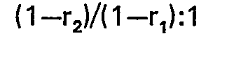
[0020] According to another aspect thereof, the present invention provides a method of controlling a multi-strand rolling mill comprising a plurality of roll stands disposed in tandem to roll simultaneously a plurality of strands, comprising the steps of tracing the trailing end and the leading end of each of a plurality of strands, and each time at least one strand end passes through each of the roll stands adjusting the ratio of the rolling speeds of the roll stands, characterised in that the ratio of the rolling speed of the roll stand(s) upstream of roll stand through which the said strand end passes and the rolling speed of the last-mentioned roll stand is:
while the rolling speed downstream of the last-mentioned stand remains unchanged, wherein r, designates the screw-down rate on the roll stand through which the said strand end has passed, when all the strands are present in the last-mentioned roll stand, and r2 designates the screw-down rate on the same roll stand when the end of the strand has passed through the said roll stand.
[0021] According to yet another aspect thereof, the present invention provides a method of controlling a multi-strand rolling mill comprising a plurality of roll stands disposed in tandem to roll simultaneously a plurality of strands, comprising the steps of tracing the trailing end and the leading end of each of a plurality of strands, and each time at least one strand end passes through each of the roll stands adjusting the ratio of the rolling speeds of the roll stands, characterised in that the ratio of the rolling speed of the roll stand through which the strand end passes, and the rolling speed of the roll stand(s) downstream of the latter roll stand is
while the rolling speed upstream of the last-mentioned roll stand remains unchanged, wherein r1 designates the screw-down rate on the roll stand through which the strand end has passed, when all the strands are present in the last-mentioned roll stand, and r2 designates the screw-down rate on the same roll stand when the strand has passed through the said roll stand.
[0022] The present invention will now be described further, by way of example, with reference to the accompanying drawings, in which:
Figure 1 is a side elevational view of the essential portion of a roll stand for rolling simultaneously a pair of strands with parts illustrated in cross sections;
Figure 2 is a cross sectional view of working rolls shown in Figure 1 illustrating one of the strand workpieces as shown in Figure 1 being rolled; and
Figure 3 is a schematic plan view of a double-strand rolling mill.
[0023] Figure 2 shows the manner in which the arrangement of Figure 1 rolls the strands 16. During the rolling of the two workpiece strands 14 and 16 the roll gap at the position of the strands 16 is determined by the upper and lower roll now designated by an upper and lower dotted circle 32 and 34 respectively. The workpiece 16 enters at an entry speed VEl into that roll gap and is rolled into a strand 36. Then the rolled strand 36 leaves with a delivery speed VDI the roll opening.
[0024] Assuming that the strand 14 leaves the upper and lower rolls after having been rolled and only the strand 16 is being rolled. At that time the roll gap at the position of the strand 16 is determined by the roll gap between the upper and the lower roll designated by the upper and lower solid circle 38 and 40 respectively. The strand 16 enters at an entry speed VE2 into that roll opening and is rolled into a strand 42. Then the rolled strand 42 leaves the roll gap at a delivery speed Vp2.
[0025] In Figure 2, the upper and lower working rolls have a common speed of rotation remaining unchanged regardless of whether or not a workpiece 14 is present between the working rolls. However, the rolled strand 42 has a ratio of its delivery speed to the circumferential speed of the roll (which is called hereinafter the rate of forward slip) larger than that of the rolled strand 36 because the rolls have screwed down the strand 42 more than the strand 36. Therefore at the outgoing side of the rolls the strand 36 travels at a lower speed than the strand 42. That is, VD1<VD2 holds. Similarly it is well known that the entry speed VEI is higher than that VE2 due to the change in rate of backward slip which implies a ratio of the entry speed of the strand to the circumferential speed of the working roll.
[0026] Figure 3 shows a multi-strand rolling mill. The arrangement illustrated comprises a pair of roll stands 44 and 46 disposed in tandem to roll a pair of working piece strand, A and B simultaneously and a pair of branched arrays each including two roll stands 48 and 50 or 49 and 51 disposed in tandem to roll only an associated one of the strands A or B. The workpiece A is being rolled on the roll stands 44, 46, 48 and 50 while it travels along loops 52 and 54 between the roll stands 46 and 48 and between the roll stands 48 and 50 respectively. The workpiece A leaves the roll stand 50 as shown by the arrow 56 in Figure 3.
[0027] On the other hand, the strand B is shown in Figure 3 as having just left the roll stand 46 and forming similar loops 53 and 55 between the roll stands 46 and 49 and between the roll stands 49 and 51 respectively. Then the workpiece B leaves the roll stand 51 as shown at the arrow 56 in Figure 3.
[0028] It will readily be seen that the roll stand 46 shown in Figure 3 corresponds to that described above in conjunction with Figure 2 because the strand B is shown in Figure 3 as having just left the roll stand 46.
[0029] In the arrangement of Figure 3 the roll stands 44, 46, 48, 49, 50 and 51 have respectively rolling speeds or speeds of the rolls as determined so that each of the roll stands is equal in mass flow in unit time of the workpiece A or B to other roll stands. However the workpiece B has already left the roll stand 46 and therefore the delivery speed of the strand workpiece A increases to V12 from VD1 while at the same time the entry speed thereof decreases to VE2 from VE1 as described above in conjunction with Figure 2. As a result, the strand A has a mass flow which is not kept constant throughout the arrangement of Figure 3.
[0030] This is true in the case when a strand following the workpiece B enters the roll stand 46. Conventional control methods for the multi- strand rolling mill have not comprised the special step of controlling such changes in entry and delivery speeds of the strand workpiece under rolling. Therefore the latter strand workpiece has greatly changed the shape of the loop 52 located downstream of that roll stand from which the one workpiece has departed. This has adversely affected the rolling effected by all the roll stands disposed downstream of the loop 52. In addition, as the roll stand 46 has a smaller mass flow than the roll stand 44 disposed upstream thereof, a compressive force is generated therebetween. This has resulted in a large defect in view of the rolling.
[0031] The present invention allows a constant mass flow to be maintained throughout a multi- strand rolling mill comprising a plurality of roll stands disposed in tandem to roll simultaneously a plurality of strand workpiece even when at least one of the strand workpieces leaves or enters one of the roll stands.
[0032] To this end, each of the manual screw-down devices 20 or 22 as shown in Figure 1 is replaced by a remotely actuatable, fast response screw-down device such as an electrically operated or an oil pressure screw-down device and there is provided tracing means for tracing the position of the leading and trailing end of each of the workpiece strands.
[0033] In Figure 2 it is assumed that each of the upper and lower rolls is rotated at a constant circumferential speed or a constant rolling speed VR and each of the plurality of strands has an entry speed VE1 and a delivery speed VD1 with the large roll gap or in the presence of all the strand workpieces on the rolls as well as an entry speed V12 and a delivery speed VD2 with the small roll gap or in the absence of at least one strand workpieces on the rolls as described above. It is further assumed that, with the roll gap large, rl, f, and b, designate a screw-down rate, a rate of forward slip and a rate of backward slip respectively while, with the roll opening small, r2, f2 and b2 designate a screw- down rate, a rate of forward slip and a rate of backward slip respectively. Under the assumed conditions,
[0035] From the above expressions it is seen that, when the strand B has left the roll stand 46 as shown in Figure 3, the entry speed of the strand workpiece A changes from its magnitude VE1 to VE2 as long as the rolling speed Vµ on the roll stand 46 remains unchanged. In order to prevent this change in entry speed from affecting the strand workpiece A, each of the roll stands disposed upstream of the roll stand 46 is required only to change the rolling speed thereon by a ratio of VE2 to VEI expressed by
[0036] Similarly the rolling speed on each of the roll stands disposed downstream of the roll stand 46 for the strand workpiece A is required to change by a ratio of VD2 to VD1 expressed by
[0037] While the measures described above have resulted from a point of view that the speed VR on the roll stand 46 remains unchanged, other measures may be adopted. More specifically, one of those measures is to change the speeds on all the roll stands disposed upstream of the roll stand 46 and including the latter alone and another measure is to change the speeds on all the roll stands disposed downstream of the roll stand 46 and including the latter alone.
[0038] The measure to change the rolling speed on each of all the upstream roll stands alone is arranged to maintain the speeds on all the downstream roll stands constant although those speeds should actually change by a factor as defined by the expression (10). From this it will readily be understood that it is required only to multiply the speeds on all the upstream roll stands including the roll stand 46 by the reciprocal of the factor defined by the expression (10). Thus it is concluded that it is sufficient to multiply the speed on the roll stand 46 by a factor (1 +f1)/(1+f2) while at the same time multiplying the speeds on the roll stands disposed upstream of the roll stand 46 by a factor expressed by
[0039] Similarly the measure to change the delivery speeds of the strand on the downstream roll stands alone results in the multiplication of the speed on the roll stand 46 by a factor of
and of the speeds on the roll stands disposed downstream thereof by a factor expressed by
[0040] In the foregoing it is to be understood that, since the rates of forward slip f, and f2 approximate unity (1), it is possible to change the roll speeds on all the roll stands upstream or downstream of the roll stand 46 by multiplying by the same factor respectively with the satisfactory result.
[0041] From the foregoing it is seen that, in order to prevent one strand workpiece leaving or entering one of roll stands from changing a roll separation on that roll stand to affect the other strand workpieces adversely, the present invention has been illustrated and described in conjunction with a control method comprising steps of tracing the trailing and leading end of each of the strands, sensing the trailing or leading end of either one thereof leaving or entering one of roll stands and changing the speed ratios of the roll stands disposed upstream or downstream of that roll stand or all the roll stands simultaneously with the sensing of the associated workpiece, it is to be understood that it is essential to change the rolling entry, delivery speeds on the roll stands upstream of that roll stand changed in number of strand workpieces being roll, and last-mentioned roll stand and those downstream thereof following a speed ratio
[0042] By changing the speeds on all the roll stands as described above, a mass flow thereof is maintained constant throughout the multi- strand tandem rolling.
[0043] While the present invention has been illustrated and described in conjunction with a two-strand tandem rolling mill as shown in Figures 2 and 3, it is to be understood that numerous changes and modification may be resorted to without departing from the scope of the present invention as set out in the claims. For example, it is to be understood that the present invention is equally applicable to any multi-strand rolling mill including a plurality of roll stands disposed in tandem to roll simultaneously more than two strand workpiece. Also the present invention has been described in conjunction with ratios with which the rolling speeds are changed on the respective roll stands, but it is noted that at least one of the strands does not leave or enter the roll stand instantaneously but that it leaves or enters the roll stand within a constant time interval as determined by the speeds thereof, the diameter of the working rolls and screwdown rate on that roll stand. As a result, it has been found that the more satisfactory result is given by making substantially equal the time interval over which the speeds are changed to the constant time interval as described above.
1. A method of controlling a multi-strand rolling mill comprising a plurality of roll
stands (44, 46) disposed in tandem to roll simultaneously a plurality of strands,
comprising the steps of tracing the trailing end and the leading end of each of a
plurality of strands (A, B), and each time at least one strand end passes through
each of the roll stands adjusting the ratio of the rolling speeds of the roll stands,
characterised in that the ratios of the rolling speed of the roll stand(s) upstream
of the roll stand through which the said strand end passes, the rolling speed of the
last-mentioned roll stand, and the rolling speed of the roll stand(s) downstream of
the latter roll stand are given by:

wherein b, and f, designate the rate of backward slip and the rate of forward slip on the roll stand through which the said strand end passes, when all the strands are present in the last-mentioned roll stand, and b2 and f2 designate the rate of backward slip and the rate of forward slip on the same roll stand when the strand end has passed through the said roll stand.
wherein b, and f, designate the rate of backward slip and the rate of forward slip on the roll stand through which the said strand end passes, when all the strands are present in the last-mentioned roll stand, and b2 and f2 designate the rate of backward slip and the rate of forward slip on the same roll stand when the strand end has passed through the said roll stand.
2. A method of controlling a multi-strand rolling mill comprising a plurality of roll
stands (44, 46) disposed in tandem to roll simultaneously a plurality of strands,
comprising the steps of tracing the trailing end and the leading end of each of a
plurality of strands (A, B), and each time at least one strand end passes through
each of the roll stands adjusting the ratio of the rolling speeds of the roll stands,
characterised in that the ratio of the rolling speed of the roll stand(s) upstream
of roll stand through which the said strand end passes and the rolling speed of the
fast-mentioned roll stand is:
while the rolling speed downstream of the last-mentioned stand remains unchanged, wherein r, designates the screw-down rate on the roll stand through which the said strand end has passed, when all the strands are present in the last-mentioned roll stand, and r2 designates the screw-down rate on the same roll stand when the end of the strand has passed through the said roll stand.
while the rolling speed downstream of the last-mentioned stand remains unchanged, wherein r, designates the screw-down rate on the roll stand through which the said strand end has passed, when all the strands are present in the last-mentioned roll stand, and r2 designates the screw-down rate on the same roll stand when the end of the strand has passed through the said roll stand.
3. A method of controlling a multi-strand rolling mill comprising a plurality of roll
stands (44, 46) disposed in tandem to roll simultaneously a plurality of strands,
comprising the steps of tracing the trailing end and the leading end of each of a
plurality of strands (A, B), and each time at least one strand end passes through
each of the roll stands adjusting the ratio of the rolling speeds of the roll stands,
characterised in that the ratio of the rolling speed of the roll stand through which
the strand end passes, and the rolling speed of the roll stand(s) downstream of the
latter roll stand is
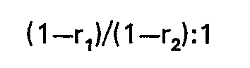
while the rolling speed upstream of the last-mentioned roll stand remains unchanged, wherein r1 designates the screw-down rate on the roll stand through which the strand end has passed, when all the strands are present in the last-mentioned roll stand, and r2 designates the screw-down rate on the same roll stand when the strand has passed through the said roll stand.
while the rolling speed upstream of the last-mentioned roll stand remains unchanged, wherein r1 designates the screw-down rate on the roll stand through which the strand end has passed, when all the strands are present in the last-mentioned roll stand, and r2 designates the screw-down rate on the same roll stand when the strand has passed through the said roll stand.
1. Verfahren zum Steuern eines mehrstrangigen Walzwerkes, mit einer Mehrzahl von Walzgerüsten
(44, 46), die im Tanden angeordnet sind, um simultan eine Mehrzahl von Strängen zu
walzen, welches die Schritte des Abtastens des nachlaufenden Endes und des voranlaufenden
Endes jedes der Mehrzahl von Strängen (A, B) umfaßt, sowie das Einstellen des Verhältnisses
der Walzgeschwindigkeiten der Walzgerüste jedesmal dann, wenn wenigstens ein Strangende
durch jedes der Walzgerüste läuft, dadurch gekennzeichnet, daß die Verhältnisse der
Walzgeschwindigkeiten der oder des Walzgerüste(s) stromaufwärts von dem Walzgerüst,
durch das das besagte Strangende läuft, die Walzgeschwindigkeit des zuletzt erwähnten
Walzgerüstes und die Walzgeschwindigkeit der oder des Walzgerüste(s) stromabwärts
von letzterem Walzgerüst gegeben werden durch

worin b1 und f1 das Ausmaß des Rückwärtsschlupfes und das Ausmaß des Vorwärtsschlupfes an dem Walzgerüst, durch das besagtes Strangende läuft, wenn alle die Stränge in dem zuletzt erwähnten Walzgerüst gegenwärtig sind, und b2 und f2 das Ausmaß des Rückwärtsschlupfes und das Ausmaß des Vorwärtsschlupfes an dem gleichen Walzgerüst bezeichnen, wenn das Strangende das Walzgerüst passiert hat.
worin b1 und f1 das Ausmaß des Rückwärtsschlupfes und das Ausmaß des Vorwärtsschlupfes an dem Walzgerüst, durch das besagtes Strangende läuft, wenn alle die Stränge in dem zuletzt erwähnten Walzgerüst gegenwärtig sind, und b2 und f2 das Ausmaß des Rückwärtsschlupfes und das Ausmaß des Vorwärtsschlupfes an dem gleichen Walzgerüst bezeichnen, wenn das Strangende das Walzgerüst passiert hat.
2. Verfahren zum Steuern eines mehrstrangigen Walzwerkes mit einer Mehrzahl von Walzgerüsten
(44, 46), die im Tandem angeordnet sind, um gleichzeitig eine Mehrzahl von Strängen
zu walzen, welches die Schritte umfaßt, das nachlaufende Ende und das voranlaufende
Ende jedes der Mehrzahl von Strängen (A, B) abzutasten und das Verhältnis der Walzgeschwindigkeiten
der Walzgerüste einzujustieren jedesmal dann, wenn wenigstens ein Strangende durch
jedes der Walzgerüste läuft, dadurch gekennzeichnet, daß das Verhältnis der Walzgeschwindigkeit
der oder des Walzgerüst(s) stromaufwärts von dem Walzgerüst, durch welches das besagte
Strangende läuft, und die Walzgeschwindigkeit des zuletzt erwähnten Walzgerüstes beträgt:
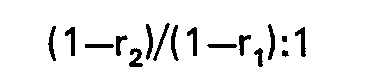
wobei die Walzgeschwindigkeit stromabwärts von dem zuletzt erwähnten Gerüst unverändert bleibt, worin R1 die Anstellgeschwindigkeit des Walzgerüstes bezeichnet, durch welches das besagte Strangende passiert ist, wenn all die Stränge in dem zuletzt erwähnten Rollenstrang gegenwärtig sind, und R2 die Anstellgeschwindigkeit auf dem gleichen Walzgerüst bezeichnet, wenn das Ende des Stranges durch das besagte Walzgerüst hindurchgegangen ist.
wobei die Walzgeschwindigkeit stromabwärts von dem zuletzt erwähnten Gerüst unverändert bleibt, worin R1 die Anstellgeschwindigkeit des Walzgerüstes bezeichnet, durch welches das besagte Strangende passiert ist, wenn all die Stränge in dem zuletzt erwähnten Rollenstrang gegenwärtig sind, und R2 die Anstellgeschwindigkeit auf dem gleichen Walzgerüst bezeichnet, wenn das Ende des Stranges durch das besagte Walzgerüst hindurchgegangen ist.
3. Verfahren zum Steuern eines mehrstrangigen Walzwerkes mit einer Mehrzahl von Walzgerüsten
(44, 46), die im Tandem angeordnet sind, um gleichzeitig eine Mehrzahl von Strängen
zu walzen, welches die Schritte umfaßt, das nachlaufende Ende und das voranlaufende
Ende jedes der Mehrzahl von Strängen (A, B) abzutasten und das Verhältnis der Walzgeschwindigkeiten
der Walzgerüste einzustellen jedesmal, wenn wenigstens ein Strangende durch jedes
der Walzgerüste läuft, dadurch gekennzeichnet, daß das Verhältnis der Walzgeschwindigkeit
des Walzgerüstes, durch welches das Strangende passiert, und die Walzgeschwindigkeit
der oder des Walzgerüste(s) stromabwärts von letzterem Walzgerüst beträgt:
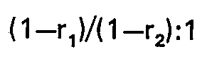
während die Walzgeschwindigkeit stromaufwärts von dem zuletzt erwähnten Walzgerüst unverändert bleibt, worin r, die Anstellgeschwindigkeit des Walzgerüstes bezeichnet, durch welches das Strangende gelaufen ist, wenn all die Stränge in dem zuletzt erwähnten Walzgerüst gegenwärtig sind, und r2 die Anstellgeschwindigkeit des gleichen Walzgerüstes bezeichnet, wenn der Strang durch das besagte Walzgerüst gelaufen ist.
während die Walzgeschwindigkeit stromaufwärts von dem zuletzt erwähnten Walzgerüst unverändert bleibt, worin r, die Anstellgeschwindigkeit des Walzgerüstes bezeichnet, durch welches das Strangende gelaufen ist, wenn all die Stränge in dem zuletzt erwähnten Walzgerüst gegenwärtig sind, und r2 die Anstellgeschwindigkeit des gleichen Walzgerüstes bezeichnet, wenn der Strang durch das besagte Walzgerüst gelaufen ist.
1. Procédé de réglage d'un laminoir à plusieurs billettes comprenant plusieurs cages
de laminage (44, 46) disposées en tandem pour laminer simultanément plusieurs billettes,
comprenant les étapes de traçage des chemins empruntés par la queue et la tête de
chacune des différentes billettes (A, B) et, à chaque fois qu'au moins une extrémité
de billette passe à travers chacune des cages de laminage, d'ajustage du rapport des
vitesses de laminage des cages de laminage, caractérisé en ce que les rapports entre
la vitesse de laminage de la ou des cages de laminage situées en amont de la cage
de laminage à travers laquelle passe ladite extrémité de billette, la vitesse de laminage
de cette cage de laminage, et la vitesse de laminage de la ou des cages de laminage
situées en aval de celle-ci, sont données par la relation:

dans laquelle b, et f, désignent le taux de recul et le taux d'avance de la cage de laminage à travers laquelle passe ladite extrémité de billette, quand toutes les billettes sont présentes dans la dernière cage de laminage mentionnée et, b2 et f2 désignent le taux de recul et le taux d'avance de la même cage de laminage, quand l'extrémité de la billette est passée à travers ladite cage de laminage.
dans laquelle b, et f, désignent le taux de recul et le taux d'avance de la cage de laminage à travers laquelle passe ladite extrémité de billette, quand toutes les billettes sont présentes dans la dernière cage de laminage mentionnée et, b2 et f2 désignent le taux de recul et le taux d'avance de la même cage de laminage, quand l'extrémité de la billette est passée à travers ladite cage de laminage.
2. Procédé de réglage d'un laminoir à plusieurs billettes comprenant plusieurs cages
de laminage (44, 46) disposées en tandem pour laminer simultanément plusieurs billettes,
comprenant les étapes de traçage des chemins empruntés par la queue et la tête de
chacune des différentes billettes (A, B) et, à chaque fois qu'au moins une extrémité
de billette passe à travers chacune des cages de laminage, d'ajustage de rapport des
vitesses de laminage des cages de laminage, caractérisé en ce que le rapport entre
la vitesse de laminage de la ou des cages de laminage situées en amont de la cage
de laminage à travers laquelle passe ladite extrémité de billette, et la vitesse de
laminage. de la dernière cage de laminage mentionnée est donnée par la relation:
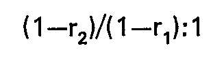
tandis que la vitesse en aval de la dernière cage mentionnée demeure inchangée, dans laquelle, r, désigne le taux de vissage de la cage de laminage à travers laquelle l'extrémité de la billette est passée, quand toutes les billettes sont présentes dans la dernière cage de laminage mentionnée, et r2 désigne le taux de vissage de la même cage de laminage quand l'extrémité de la billette est passée à travers ladite cage de laminage.
tandis que la vitesse en aval de la dernière cage mentionnée demeure inchangée, dans laquelle, r, désigne le taux de vissage de la cage de laminage à travers laquelle l'extrémité de la billette est passée, quand toutes les billettes sont présentes dans la dernière cage de laminage mentionnée, et r2 désigne le taux de vissage de la même cage de laminage quand l'extrémité de la billette est passée à travers ladite cage de laminage.
3. Procédé de réglage d'un laminoir à plusieurs billettes comprenant plusieurs cages
de laminage (44, 46) disposées en tandem pour laminer simultanément plusieurs billettes,
comprenant les étapes de traçage des chemins empruntés par la queue et la tête de
chacune des différentes billettes (A, B) et, à chaque fois qu'au moins une extrémité
de billette passe à travers chacune des cages de laminage, d'ajustage du rapport des
vitesses de laminage des cages de laminage, caractérisé en ce que le rapport entre
la vitesse de laminage de la cage de laminage à travers laquelle passe l'extrémité
de la billette, et la vitesse de laminage de la ou des cages de laminage situées en
aval de cette dernière est donnée par la relation
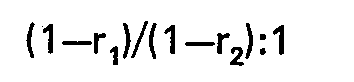
tandis que la vitesse de laminage en amont de la dernière cage de laminage mentionnée demeure inchangée, dans laquelle r1 désigne le taux de vissage de la cage de laminage à travers laquelle l'extrémité de la billette est passée, quand toutes les billettes sont présentes dans la dernière cage de laminage mentionnée et, rz désigne le taux de vissage de la même cage de laminage quand la billette est passée à travers ladite cage de laminage.
tandis que la vitesse de laminage en amont de la dernière cage de laminage mentionnée demeure inchangée, dans laquelle r1 désigne le taux de vissage de la cage de laminage à travers laquelle l'extrémité de la billette est passée, quand toutes les billettes sont présentes dans la dernière cage de laminage mentionnée et, rz désigne le taux de vissage de la même cage de laminage quand la billette est passée à travers ladite cage de laminage.