| (19) |
 |
|
(11) |
EP 0 064 087 B1 |
| (12) |
EUROPEAN PATENT SPECIFICATION |
| (45) |
Mention of the grant of the patent: |
|
16.01.1985 Bulletin 1985/03 |
| (22) |
Date of filing: 30.04.1981 |
|
|
| (54) |
Cylinder lock resistant to picking
Auftastsicheres Zylinderschloss
Serrure cylindrique de sûreté contre le crochetage
|
| (84) |
Designated Contracting States: |
|
AT BE CH DE FR IT LI LU NL SE |
| (43) |
Date of publication of application: |
|
10.11.1982 Bulletin 1982/45 |
| (71) |
Applicant: Huang, Tsao-Keng |
|
Shui Li Hsiang
Nan Tou Hsien (TW) |
|
| (72) |
Inventor: |
|
- Huang, Tsao-Keng
Shui Li Hsiang
Nan Tou Hsien (TW)
|
| (74) |
Representative: Flügel, Otto, Dipl.-Ing. et al |
|
Lesser & Flügel,
Postfach 81 05 06
81905 München
81905 München (DE) |
|
| |
|
| Note: Within nine months from the publication of the mention of the grant of the European
patent, any person may give notice to the European Patent Office of opposition to
the European patent
granted. Notice of opposition shall be filed in a written reasoned statement. It shall
not be deemed to
have been filed until the opposition fee has been paid. (Art. 99(1) European Patent
Convention).
|
[0001] The present invention concerns a cylinder lock and a key for unlocking this lock,
comprising a body with a hook, and locking means to prevent the hook from being pulled
out from locked position to unlocked position; a rotatable cylinder with its upper
end structured so as to co-operate with the locking means to allow the hook to be
pulled out when the cylinder is turned to a certain position; a bush with one of its
ends forming a tortuous entrance into which the key can be screwed, said bush being
fixedly secured in the body.
[0002] Basically conventional cylinder keys comprise substantially a planar key with an
indented edge, a cylinder, and a body internally provided with a plurality of pin
tumblers resiliently retained in a tunnel orienting to the keyway. When a key with
a contoured profile on one edge is inserted into the keyway from the keyhole, the
pins will be contacted by these undulation, and once the correct key is inserted thereinto,
then the pin tumblers will all be arranged in such a position as to allow the cylinder
to be turned. Straight in structure, the keyway of such conventional lock are liable
to be picked by probing a wire therein. Moreover, the resilient means, generally springs,
which urge the pin tumblers against the notches of a key at a specific level to discriminate
if the key is the correct one, are hair-spring thin. After some use accumulation of
rust or dirt may lead to failure of such fine parts, thus reducing the life of the
lock.
[0003] Still further, traditional locks are complicated in their construction which means
that these are difficult to assemble and to manufacture and which also means that
the cost of production is high.
[0004] There is known a lock of this kind according to the generic motion of the main claim
(US-A-1 849 070) which, however, is not only difficult to manufacture but, in addition,
does not offer reliable protection against picking.
[0005] Finally, it is known (US-A-1 526 728) to provide a spiral entrance with locks into
which the key can be screwed.
[0006] it is the main object of this invention to provide a cylinder lock which obviates
the above defects in that the lock is more secure against unauthorised unlocking without
the use of the correct key and also that the use of spring loaded wards is obviated.
Thus the life of the lock is increased.
[0007] In a cylinder lock and a key of the type indicated in the prior art portion of claim
1 this object in conformity with the present invention is reached in that:
the tortuous entrance in the bush has a spiral shape having pitch and lead angle corresponding
to the spiral provided on the key;
the bush is provided with a plurality of ward means receivable in a plurality of female
locking means, to prevent the rotation of the cylinder;
the key is provided with a plurality of male locking means receivable in corresponding
said female locking means, when the key is screwed into the spiral entrance of the
lock and pushed into the lock, said male locking means acting on the ward means engaged
into the female locking means so as to relieve the effect of the ward means and allow
the rotation of the cylinder.
[0008] A preferred feature of this invention is that the resilient means can be economically
a thick metal reeds instead of the springs fabricated by extremely fine wire, thus
enhancing the durability and reducing the cost of the manufacture thereof.
[0009] Other and important objects of this invention will be apparent from the following
description, claims and accompanying drawing.
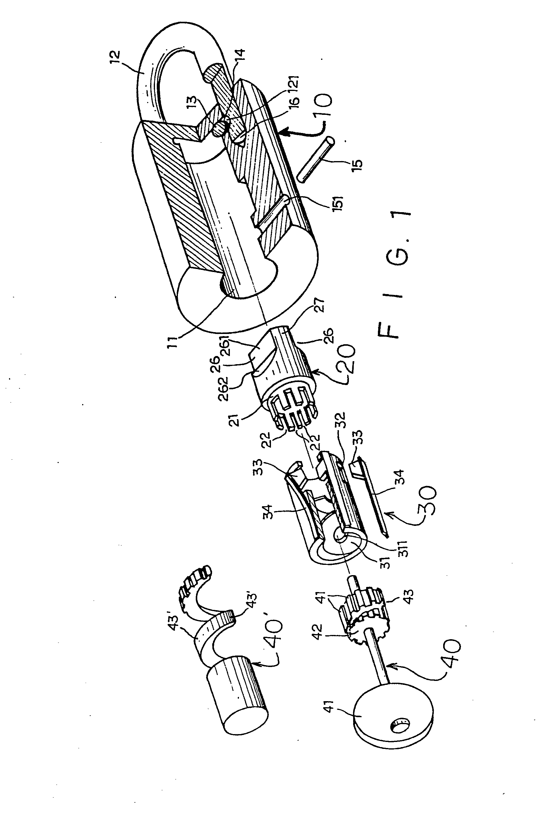
Figure 1 is an exploded perspective view of a cylinder lock constructed in accordance
with the invention;
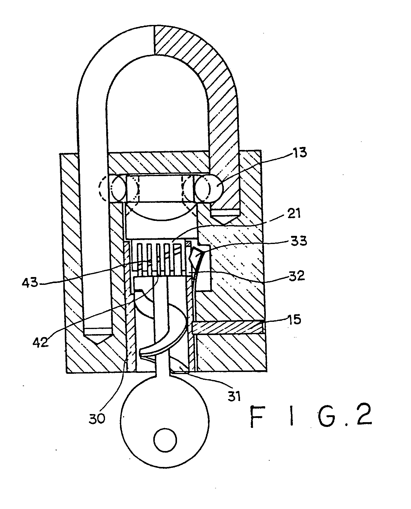
Figure 2 is a longitudinal cross-sectional view of the assembled lock of Figure 1
with the key in position;
[0010] Referring now to the drawings, the cylinder lock according to the invention includes
a body, a cylinder, a bush and a key, generally designated by reference numerals (10),
(20), (30), and (40) respectively.
[0011] In the preferred embodiment of Figure 1, the body has a bore (11) which receives
cylinder (20) and bush (30), the former being rotatable therein, whereas the latter
being immovably secured in place, for example by passing a pin (15) through hole (151).
[0012] Hook (12) has a recess (121), the dimension and the position of which allow one part
of ball (13) retained within a hole (14) to enter when the hook is in locked position
in blind hole (16) so that it cannot be pull up. Like structure may be formed at the
other leg of hook (12). (See Figure 2).
[0013] At one end of cylinder (20) there are provided with two opposite recesses (26), each
of which is formed by a cutout defined by two intersecting faces (261) (262). When
the cylinder is turned to a position such that face (261) directly opposite to ball
(13), i.e. normal to the long axis of hole (14), the clearance between the inner wall
of body (10) and the upper end of cylinder is broadest and enough to allow the ball
to totally leave recess (121) to free hook (12) so that the latter can be unlocked
(see Figure 2). Similarly, when cylinder (20) is turned in reverse direction, the
non-recessed portion (27) urges ball (13) back into recess (121) to lock hook (12).
[0014] To allow only selective entry of specific keys, the outer end of bush (30) is provided
with a spiral entrance (31) which is structured so that only an object with spiral
structure of which the pitch and lead angle substantially coincides with that of the
entrance is allowed to be screwed thereinto. Further, to discriminate whether or not
the key thus enters is the correct one, the lower end (21) of cylinder (20), which
is nested in the upper end of bush (30), forms a plurality of slots (22) spaced apart
from each other around the periphery of end (21) and extending along the length of
cylinder (20). Complementary to these slots, the end of key (40), in a preferred embodiment,
forms an enlarged end (42) provided with a plurality of projectors (41) arranged around
the periphery thereof, the dimension and position of which projections substantially
coincide with the slots (22), and at the site the upper end of bush corresponding
to each slot (22) there is a hole (32), through which a ward piece (33) is resiliently
urged inwardly to reach one of said slots (22). The projections are preferably ridged
extending along the length of said key. Preferably ward piece (33) is inseparably
fixed to one end of a spring reed (34), the other end of the latter being secured
to the outer wall of bush (30) by, for example, welding or by a screw (not shown).
[0015] To allow key (40) to be screwed into the lock through the spiral entrance (31), there
is provided a spiral groove (43) extending across the projections (41), which spiral
groove (43) is bitten into by the helical edge (31 1 ) of spiral entrance (31), thereby
allowing the key to be screwed into the bush to reach cylinder. When the whole length
of spiral groove passes through the spiral entrance, the key can be directly pushed
axially so that the projections fit into their corresponding slots.
[0016] With the projections, the enlarged end (42) of the key looks like a gear. However,
unlike the gears, the width of each projection and the distance between any two adjacent
projections may differ greatly at random, depending on the design of the slots (22).
As all of the pitch and the lead angle of the spiral entrance, and the position and
number of the slots may vary arbitrarily, the probability that a lock happened to
be unlocked by the key of another such lock is extremely low, thus ensuring high security
and reliability of this invention.
[0017] An alternative modification of the key (40), designated by (40'), is also feasible.
It has a spiral shank (43'), with a length of its front forming a plurality of projections
at the outer side. To adapt to such modification, the slots (22) of cylinder (20)
and the ward pieces (33) and holes (32) of bush (30) must be arranged in a spiral
trajectory instead of a circumference. This is easy to understand, and therefore not
illustrated in the drawing. However, the spiral shank must be structured so that it,
before reaching the slots, can be pushed inwardly a short distance in axial direction
to fit its projection into mating slots.
1. A cylinder lock and a key for unlocking this lock, comprising:
- a body (10) with a hook (12), and locking means (13) to prevent the hook (12) from
being pulled out from locked position to unlocked position;
- a rotatable cylinder (20) with its upper end structured so as to co-operate with
the locking means (13) to allow the hook (12) to be pulled out when the cylinder (20)
is turned to a certain position;
- a bush (30) with one of its ends forming a tortuous entrance into which the key
(40, 40') can be screwed said bush (30) being fixedly secured in the body (10), characterized
in that:
-the tortuous entrance (31) in the bush (30) has a spiral shape having pitch and lead
angle corresponding to the spiral provided on the key;
- the bush (30) is provided with a plurality of ward means receivable in a plurality
of female locking means, to prevent the rotation of the cylinder;
- the key (40, 40') is provided with a plurality of male locking means receivable
in corresponding said female locking means, when the key (40, 40') is'screwed into
the spiral entrance (31) of the lock and pushed into the lock, said male locking means
acting on the ward means engaged into the female locking means so as to relieve the
effect of the ward means and allow the rotation of the cylinder (20).
2. The lock and key according to Claim 1, wherein said locking means to prevent said
hook from being pulled are a ball (13) re- ciprocably retained in a hole (14) of said
body (10) communicating with a recess (121) on one leg of said hook, in a manner such
that when said lock is in locked condition, part of said ball (13) is urged by the
upper and of said cylinder (20) to fit into said recess, and when said lock is in
unlocked condition, said ball can completely leave said recess (121).
3. The lock and key according to Claim 1 or 2, wherein the upper end of said cylinder
(20) has at least a recessed portion which allow said ball (13) to enter when said
cylinder (20) is turned to unlocked position.
4. The lock and key according to Claim 1, wherein said ward means are a plurality
of ward pieces (33) resiliently urged to engage with said female locking means of
said cylinder (20).
5. The lock and key according to claim 1, wherein said female locking means are a
plurality of slots (22) arranged around the periphery of said cylinder (20), extending
axially, and opening at the lower end of said cylinder.
6. The lock and key according to claim 1, 4 or 5, wherein said male locking means
are a plurality of projections (41) corresponding to said slots (22) and are designed
such that when one of such a projection (41) engages with its corresponding slot (22),
the corresponding ward piece (33) is repelled outward and no longer prevent the rotation
of said cylinder (20).
7. The lock and key according to Claim 1, 4, 5 or 6, wherein said bush (30) is provided
with a hole at each side of said ward piece (33) to allow the latter to pass through.
8. The lock and key according to Claim 1 or 4, wherein each of said ward pieces (33)
is fixed to a spring reed fixed on the outer wall of said bush and resiliently urging
said ward piece toward said slot.
9. The lock and key according to Claim 6, characterised in that said projections (41)
are a plurality of ridges extending along the length of said key (40) and spaced around
an enlarged portion near the tip end of said key (40).
10. The lock and key according to Claim 9, wherein the enlarged portion of the key
(40) is provided with a spiral groove (43) around said portion and cutting across
said ridges; the width, depth, pitch, and lead angle of said groove (43) being such
that it enable said key to be screwed through said spiral entrance (31) into said
lock.
11. The lock and key according to Claim 1, characterised in that the anterior portion
of the key (40') is a spiral shank with at least a length thereof provided with a
plurality of projections corresponding to the slots of said cylinder, the dimension,
pitch and lead angle of which shank being such that it can be screwed into said lock
through said spiral entrance (31) and then pushed axially a distance so that its projections
may fit into corresponding slots (22) of said cylinder (20).
12. The lock and key according to Claim 1, wherein the spirality of said entrance
of said key can be either clockwise or counterclockwise viewing from the gripping
end of the key.
1. Serrure à barillet et clé de déverrouillage de cette serrure comprenant:
- un corps (10) avec un crochet (12) et des dispositifs de verrouillage (13) empêchant
de tirer le crochet (12) vers l'extérieur en le faisant passer de la position verrouillée
à la position déverrouillée;
- un barillet tournant (20) dont l'extrémité supérieure est structurée de façon à
coopérer avec les dispositifs de verrouillage (13) pour permettre de tirer le crochet
(12) vers l'extérieur lorsque le barillet (20) est tourné dans une certaine position;
- un douille (30) formant à l'une de ses extrémités une entrée contournée dans laquelle
la clé (40, 40') peut être vissée, cette douille (30) étant solidement fixée au corps
(10), caractérisé par le fait que
- l'entrée contournée (31) de la douille (30) a une forme en spirale dont le pas et
l'angle d'avance correspondent à la spirale existant sur la clé;
- la douille (30) présente une pluralité de gardes qui peuvent pénétrer dans une pluralité
de dispositifs de verrouillage femelles pour empêcher la rotation du barillet;
- la clé (40, 40') présente une pluralité de dispositifs de verrouillage mâles pouvant
pénétrer dans les dispositifs de verrouillage femelles correspondants lorsque la clé
(40, 40') est vissée dans l'entrée en spirale (31) de la serrure et poussée vers l'intérieur
de la serrure, ces dispositifs de verrouillage mâles agissant sur les gardes engagées
dans les dispositifs de verrouillage femelles de façon à supprimer l'effet des gardes
et à permettre la rotation du barillet (20).
2. Serrure et clé selon la revendication 1, dans lesquelles les dispositifs de verrouillage
empêchant de tirer le crochet vers l'extérieur sont constitués d'une bille (13) pouvant
être ou non maintenue dans un orifice (14) du corps (10) en communication avec un
évidement (121) ménagé dans un bras du crochet, de sorte que si la serrure est en
position verrouillée, une partie de cette bille (13) est poussée par l'extrémité supérieure
du barillet (20) et pénètre dans l'évidement et si la serrure est en position déverrouillée,
cette bille est complètement dégagée de l'évidement (121).
3. Serrure et clé selon l'une des revendications 1 ou 2, dans lesquelles l'extrémité
supérieure du barillet (20) présente au moins une portion dégagée pour permettre à
cette bille (13) de pénétrer quand le barillet (20) est tourné en position déverrouillée.
4. Serrure et clé selon la revendication 1, dans lesquelles le dispositif de garde
est constitué d'une pluralités de gardes (33) poussées de façon élastique à s'engager
dans des dispositifs femelles de verrouillage dudit barillet (20).
5. Serrure et clé selon la revendication 1, dans lesquelles les moyens de verrouillage
femelles sont constitués d'une pluralité de fentes (22) disposées sur la pourtour
du barillet (20), orientées dans le sens de l'axe et s'ouvrant à l'extrémité inférieure
dudit barillet.
6. Serrure et clé selon l'une des revendications 1, 4 ou 5 dans lesquelles les dispositifs
de verrouillage mâles sont constitués d'une pluralité de parties en saillie (41) correspondant
aux fentes (22) et ont une structure telle que si l'une des parties en saillie (41)
s'engage dans la fente correspondante (22), la garde correspondante (33) est repoussée
vers l'extérieur et n'empêche plus la rotation du barillet (20).
7. Serrure et clé selon l'une des revendications 1, 4, 5 ou 6 dans lesquelles la douille
30 présente un orifice à chaque position d'une garde (33) pour permettre à cette dernière
de passer par cet orifice.
8. Serrure et clé selon l'une des revendications 1 ou 4, dans lesquelles chacune des
gardes (33) est fixée à une lame de ressort elle-même maintenue sur la paroi extérieure
de la douille et poussant de façon élastique la garde vers la fente.
9. Serrure et clé selon la revendication 6, caractérisées par le fait que les parties
en saillie (41) sont constituées d'une pluralité de nervures orientées sur la longueur
de la clé (40) et espacées autour d'une partie élargie voisine de l'extrémité de la
clé (40).
10. Serrure et clé selon la revendication 9, dans lesquelles la partie élargie de
la clé (40) présente une nervure en spirale (43) coupant les nervures; la largeur
la profondeur, le pas et l'angle d'avance de cette nervure (43) étant tels qu'ils
permettent de visser la clé dans l'entrée en spirale (31) de la serrure.
11. Serrure et clé selon la revendication 1, caractérisées par le fait que la partie
antérieure de la clé (40') est une tige en spirale dont au moins une portion de la
longueur présente une pluralité de parties en saillies correspondant aux fentes du
barillet, la dimension, le pas et l'angle d'avance de cette tige étant tels que la
clé puisse être vissée dans la serrure par l'entrée en spirale (31) et ensuite poussée
dans la direction axiale sur une certaine distance de façon que ses parties en saillie
puissent pénétrer dans les fentes correspondantes (22) dudit barillet (20).
12. Serrure et clé selon la revendication 1, dans lesquelles les caractéristiques
de la spirale de l'entrée de la clé peuvent correspondre à une rotation dans le sens
des aiguilles d'une montre ou dans le sens inverse vue depuis l'extrémité par laquelle
on tient la clé.
1. Zylinderschloß und Schlüssel zur Entriegelung des Schlosses, mit einem einen Haken
(12) aufweisenden Körper (10) und Verriegelungseinrichtungen (13) zur Verhinderung,
daß der Haken (12) aus der verriegelten Lage heraus in die entriegelte Lage gezogen
wird, mit einem drehbaren Zylinder (20), dessen oberes Ende mit den Verriegelungseinrichtungen
(13) zusammenwirkend ausgebildet ist und ermöglicht, daß der Haken (12) herausgezogen
werden kann, wenn der Zylinder (20) in eine bestimmte Lage gedreht wird, mit einer
Hülse (30), deren eines Ende einen gewundenen Eingang bildet, in welchen der Schlüssel
(40, 40') hineingedreht bzw. hineingeschraubt werden kann, wobei die Hulse (30) in
dem Körper (10) verdrehfest angeordnet ist, dadurch gekennzeichnet, das der gewundene
Eingang (31) in der Hülse (30) eine Spiralform aufweist, der Steigungswinkel bzw.
Ganghöhe jener der an dem Schlüssel ausgebildeten Spiralform entspricht, daß die Hülse
(30) mit einer Veilzahl von Zuhaltungseinrichtungen versehen ist, die zur Verhinderung
der Drehung des Zylinders in einer Vielzahl von aufnehmenden Verriegelungseinrichtungen
aufgenommen werden, daß der Schlüssel (40, 40') mit einer Vielzahl von eintretenden
Verriegelungseinrichtungen versehen ist, die in den aufnehmenden Verriegelungseinrichtungen
aufgenommen werden, wenn der Schlüssel (40, 40') in den spiralförmigen Eingang (31)
des Schlosses hineingedreht und in das Schloß geschoben wird, wobei die eintretenden
Verriegelungseinrichtungen auf die in die aufnehmenden Verriegelungseinrichtungen
eingreifenden Zuhaltungseinrichtungen derart einwirken, daß die Wirkung der Zuhaltungseinrichtungen
aufgehoben und die Drehung des Zylinders (20) ermöglicht wird.
2. Schloß und Schlüssel nach Anspruch 1, dadurch gekennzeichnet, daß die das Herausziehen
des Hakens verhindernden Verriegelungseinrichtungen in Form einer Kugel (13) vorgesehen
sind, die hin- und herbewegbar in einem Loch (14) des körpers (10) befindlich ist
und mit einer Vertiefung (121) an einem Schenkel des Hakens derart kommuniziert, daß
im verriegelten Zustand des Schlosses ein Teil der Kugel (13) durch das obere Ende
des Zylinders (20) paßgerecht in die Vertiefung gedrückt wird und daß im entriegelten
Zustand des Schlosses die Kugel vollständig aus der Vertiefung (121) heraustreten
kann.
3. Schloß und Schlüssel nach Anspruch 1 oder 2, dadurch gekennzeichnet, daß das obere
Ende des Zylinders (20) mindestens einen Vertiefungsbereich aufweist, in welchen die
Kugel (13) eintreten kann, wenn der Zylinder (20) in die Entriegelungslage gedreht
wird.
4. Schloß und Schlüssel nach Anspruch 1, dadurch gekennzeichnet, daß die Zuhaltungseinrichtungen
in Form einer Veilzahl von Zuhaltungsdaumen (33) vorgesehen sind, die federelastisch
in Eingriff mit den aufnehmenden Verriegelungseinrichtungen des Zylinders (20) gebracht
werden.
5. Schloß und Schlüssel nach Anspruch 1, dadurch gekennzeichnet, daß die aufnehmenden
Verriegelungseinrichtungen in Form einer Vielzahl von Schlitzen (22) vorgesehen sind,
die um die Peripherie des Zylinders (20) angeordnet sind, sich in axialer Richtung
erstrecken und sich am unteren Ende des Zylinders (20) öffnen.
6. Schloß und Schlüssel nach einem der Ansprüche 1, 4 oder 5, dadurch gekennzeichnet,
daß die eintretenden Verriegelungseinrichtungen in Form einer Veilzahl von Vorsprüngen
(41) vorgesehen sind, die den Schlitzen (22) entsprechen und so ausgebildet sind,
daß bei Ineinandergreifen eines dieser Vorsprünge (41) mit dem entsprechenden Schlitz
(22) der entsprechende Zuhaltungsdaumen (33) nach außen gestoßen wird und die Drehung
des Zylinders (20) nicht mehr behindert.
7. Schloß und Schlüssel nach einem der Ansprüche 1, 4, 5 oder 6, dadurch gekennzeichnet,
daß die Hülse (30) auf jeder Seite des Zuhaltungsdaumens (33) eine Öffnung aufweist,
die den Durchtritt des Zuhaltungsdaumens erlaubt.
8. Schloß und Schlüssel nach Anspruch 1 oder 4, dadurch gekennzeichnet, daß jeder
der Zuhaltungsdaumen (33) an einer Blattfeder befestigt ist, die ihrerseits an der
Außenwand der Hülse festgelegt ist und den Zuhaltungsdaumen in Richtung Schlitz drückt.
9. Schloß und Schlüssel nach Anspruch 6, dadurch gekennzeichnet, daß die Vorsprünge
(41) in Form einer Veilzahl von Rippen vorgesehen sind, die sich entlang der Länge
des Schlüssels (40) erstrecken und rund um den vergrößerten Bereich in der nähe des
oberen Endes des Schlüssels (40) voneinander beabstandet angeordnet sind.
10. Schloß und Schlüssel nach Anspruch 9, dadurch gekennzeichnet, daß der vergrößerte
Bereich des Schlüssels (40) eine Spiralnut bzw. spiralförmige Vertiefung (43) aufweist,
die rund um diesen Bereich verläuft und die Rippen durchschneidet, wobei Breite, Tiefe,
Steigungswinkel und Ganghöhe der Vertiefung (43) so bemessen sind, daß der Schlüssel
über den spiralförmigen Eingang (31) in das Schloß gedreht bzw. geschraubt werden
kann.
11. Schloß und Schlüssel nach Anspruch 1, dadurch gekennzeichnet, daß der vordere
Bereich des Schlüssels (40') als spiralförmiger Schaft ausgebildet ist, der mindestens
über einen Abschnitt seiner Länge mit einer Vielzahl von den Schlitzen des Zylinders
entsprechenden Vorsprüngen versehen ist, wobei Größe, Steigungswinkel und Ganghöhe
des Schafts so bemessen sind, daß letzterer über den spiralförmigen Eingang (31) in
das Schloß hineingedreht werden und dann in axialer Richtung ein Stück geschoben werden
kann, so daß die Vorsprünge ihre paßgerechte Lage in den entsprechenden Schlitzen
(22) des Zylinders (20) inenehmen.
12. Schloß und Schlüssel nach Anspruch 1, dadurch gekennzeichnet, daß die Spiralform
des Eingangs des Schlüssels von dem Griffende des Schlüssels aus gesehen entweder
mit oder gegen den Uhrzeigersinn verlaufend ausgebildet sein kann.