| (19) |
 |
|
(11) |
EP 0 069 454 B1 |
| (12) |
EUROPEAN PATENT SPECIFICATION |
| (45) |
Mention of the grant of the patent: |
|
09.11.1988 Bulletin 1988/45 |
| (22) |
Date of filing: 25.05.1982 |
|
|
| (54) |
Method and apparatus for compressing gas
Verfahren und Vorrichtung zur Verdichtung von Gasen
Méthode et dispositif pour comprimer un gaz
|
| (84) |
Designated Contracting States: |
|
AT BE CH DE FR GB IT LI LU NL SE |
| (30) |
Priority: |
18.06.1981 GB 8118865
|
| (43) |
Date of publication of application: |
|
12.01.1983 Bulletin 1983/02 |
| (73) |
Proprietor: AIR PRODUCTS AND CHEMICALS, INC. |
|
Allentown, Pennsylvania 18105 (US) |
|
| (72) |
Inventor: |
|
- Allam, Rodney John
Guildford
Surrey (GB)
|
| (74) |
Representative: Lucas, Brian Ronald |
|
Lucas & Co.
135 Westhall Road
Warlingham
Surrey CR6 9HJ
Warlingham
Surrey CR6 9HJ (GB) |
| (56) |
References cited: :
FR-A- 1 281 075
FR-A- 2 317 482
|
FR-A- 2 313 581
|
|
| |
|
|
- Dr. R. Gregorig, Grundlagen der chemischen Technik: "Wärmeaustausch und Wärmeaustauscher",
Verlag Sauerländer Aarau, pages 444-447
|
|
| |
|
| Note: Within nine months from the publication of the mention of the grant of the European
patent, any person may give notice to the European Patent Office of opposition to
the European patent
granted. Notice of opposition shall be filed in a written reasoned statement. It shall
not be deemed to
have been filed until the opposition fee has been paid. (Art. 99(1) European Patent
Convention).
|
[0001] This invention relates to a method and an apparatus for compressing gas.
[0002] A number of industrial processes rely on the continuous supply of gas at elevated
pressure. Amongst these are the cryogenic separation of air where the feed air is
typically required at 5 to 9 bar A, and the synthesis of ammonia where the ammonia
synthesis gas is typically required at between 100 and 250 bar A.
[0003] Heretofore, it has been considered good practice to compress gas in a generally isothermal
manner and for this reason all compressors on air separation plant and ammonia plant
known to us comprise a plurality of compression stages separated by inter-coolers.
The inter-coolers are normally cooled with air or water and whilst attempts have been
made to recover energy from the cooling water the amount of useful energy recovered
has been minimal due to the relatively low temperature of the cooling water which
is typically between 80°C and 130°C.
[0004] FR-A-2 317 482 discloses a process in which the inter-coolers are omitted and the
air is compressed adiabatically. The hot compressed air is then cooled by heating
and vaporizing a fluorocarbon. The vapour is then expanded through an expansion turbine
which is used to assist in driving the compressor. Whilst this arrangement substantially
reduces the fuel used compared with an adiabatic compressor our calculations show
that the arrangement disclosed gives minimal (if any) advantage compared with a standard
isothermal compression system.
[0005] FR-A-1 281 075 discloses a process in which air is compressed in a compressor provided
with inter-cooling. The compressed air leaving the final stage of the compressor is
passed in cocurrent heat exchange with water at low pressure. The warm water is pumped
to a high pressure and vaporized in a boiler. The high pressure steam thus produced
is expanded through a turbine which is used to drive the compressor. This process
has not gained commercial acceptance since the amount of useful energy which can be
recovered is minimal.
[0006] An object of at least preferred embodiments of the present invention is to provide
a process and an apparatus for compressing gas which consumes less fuel than conventional
isothermal compression systems.
[0007] This objective is achieved by steps which are totally contrary to long established
chemical engineering practice.
[0008] Thus, we have discovered that, contrary to established practice, compression should
be carried out substantially adiabatically. Although the amount of fuel required to
compress a gas adiabatically is greater than the amount of fuel required to compress
the gas isothermally, under favourable conditions, useful energy can be recovered
from the adiabatically compressed gas which, when used, directly or indirectly, to
assist in driving the compressor, can result in less fuel being used to compress the
gas than is used in a conventional isothermal compressor. In contrast, the amount
of useful energy which can be recovered from the inter-coolers associated with conventional,
i.e. isothermal, compressors is, in comparison, very small.
[0009] According to the present invention there is provided a method of compressing gas,
which method comprises the steps of compressing said gas, cooling said compressed
gas by heat exchange with a coolant, further heating and vaporizing said coolant,
and expanding said vaporized coolant through a turbine to provide energy to compress
said gas, characterised in that:
a) when said gas has a Cp/Cv ratio greater than 1.55 it is compressed in a substantially
adiabatic manner through a pressure ratio of between 2.5:1 and 8:1;
b) when said gas has a Cp/Cv ratio between 1.55 and 1.33 it is compressed in a substantially
adiabatic manner through a pressure ratio of between 4:1 and 30:1; and
c) when said gas has a Cp/Cv ratio less than 1.33 it is compressed in a substantially
adiabatic manner through a pressure ratio of between 2.5:1 and 75:1.
[0010] In many installations it is envisaged that there will only be a single gas compressor
and in such an embodiment the energy will be returned, either directly or indirectly,
to assist in driving the single compressor. In the case of a train of compressors
the energy associated with the coolant leaving, for example the first compressor,
could be used to assist in driving, for example the second or third compressor in
the train although it is envisaged that, in practice, the energy would be returned
to a common source for allocation to all the compressors.
[0011] As indicated above, the optimum pressure ratio through which the gas should be compressed
varies according to the ratio of the specific heat at constant pressure to the specific
heat at constant volume (Cp/Cv) of the gas and according to the coolant. For most
practical purposes, the coolant will be water and under typical operating conditions,
for a gas having a Cp/Cv of about 1.67 (i.e. a monatomic gas) the optimum pressure
ratio is about 4:1 with pressure ratios in the range 2.5:1 to 8:1 and more preferably
3:1 to 7:1 being quite acceptable. In the case of a gas with a Cp/Cv of 1.4, (i.e
a diatomic gas) the optimum pressure ratio is about 7:1 with pressure ratios in the
range 4:1 to 30:1 and more preferably 4:1 to 20:1 being beneficial. In the case of
a gas with a Cp/Cv of 1.25 (i.e. a triatomic gas) the optimum pressure ratio is about
15:1 with pressure ratios in the range 2.5:1 to 75:1 and more preferably 6:1 to 50:1
being beneficial. For gases of lower Cp/Cv the optimum pressure ratio will be higher.
For a mixture of gases the optimum pressure ratio can be calculated knowing the ratio
of Cp/Cv. However, for initial evaluation purposes a gas mixture with a Cp/Cv greater
than 1.55 can be regarded as having the same optimum and preferred pressure ratios
as a monatomic gas. Similarly, a gas mixture with a Cp/Cv less than 1.33 can be regarded
as having the same optimum and preferred pressure ratios as a triatomic gas. Gas mixtures
with a Cp/Cv between 1.33 and 1.55 can be regarded as having the same optimum and
preferred pressure ratios as a diatomic gas.
[0012] It would appear that there is a pressure ratio beyond which the present invention
has little or no advantage over the prior art isothermal systems. This pressure ratio
is in excess of an estimated 9:1 for gases where Cp/Cv = 1.67, in excess of an estimated
32:1 for gases where Cp/Cv = 1.4 and in excess of an estimated 80:1 for a gas where
Cp/Cv = 1.25.
[0013] Preferably, the coolant is water under superatmospheric pressure. In such an embodiment
the steam formed by said further heating is preferably expanded through a steam turbine
mechanically connected to said compressor.
[0014] Heat exchange from the hot gas to the coolant may be direct or indirect.
[0015] Preferably, the water is at a pressure substantially equal to the pressure at the
inlet of said steam turbine.
[0016] The present invention also provides an apparatus for compressing gas, which apparatus
comprises a compressor, a heat exchanger in which heat from compressed gas can be
transferred to a coolant, means for further heating and vaporizing said coolant, and
a turbine in which said vaporized coolant can be expanded for recovering at least
part of the heat transferred to said coolant and using it to compress said gas, characterised
in that said compessor is designed to compress said gas substantially adiabatically
through a pressure ratio of:
a) between 2.5:1 and 8:1 when said gas has a Cp/Cv ratio greater than 1.55;
b) between 4:1 and 30:1 when said gas has a Cp/Cv ratio between 1.55 and 1.33; and
c) between 2.5:1 and 75:1 when said gas has a Cp/Cv ratio less than 1.33.
[0017] Preferably, said means for further heating and vaporizing said coolant comprises
a boiler.
[0018] Advantageously, said coolant is water.
[0019] The present invention is applicable to substantially all situations in which gases
are compressed. Several applications are of particular commercial importance and the
present invention therefore provides an air separation plant comprising an apparatus
in accordance with the invention; an ammonia synthesis plant comprising an apparatus
in accordance with the invention; an ethylene plant comprising an apparatus in accordance
with the invention; a natural gas compression and/or liquifaction plant comprising
an apparatus in accordance with the invention; a methanol plant comprising an apparatus
in accordance with the present invention; and a urea synthesis plant comprising an
apparatus in accordance with the invention.
[0020] For a better understanding of the present invention reference will now be made, by
way of example, to the accompanying drawings in which:
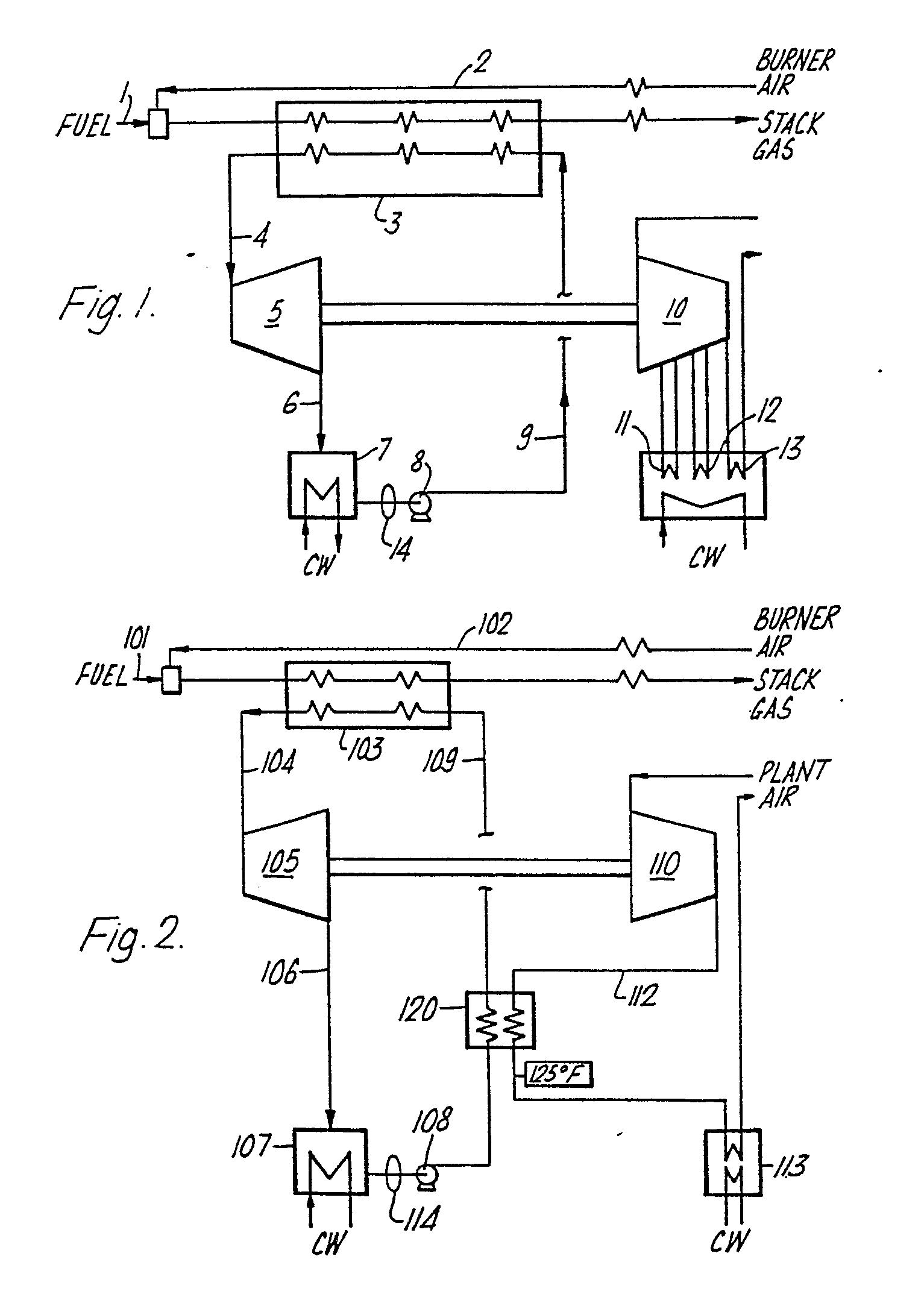
Figure 1 shows a known apparatus for compressing gas;
Figure 2 shows an apparatus in accordance with the invention; and
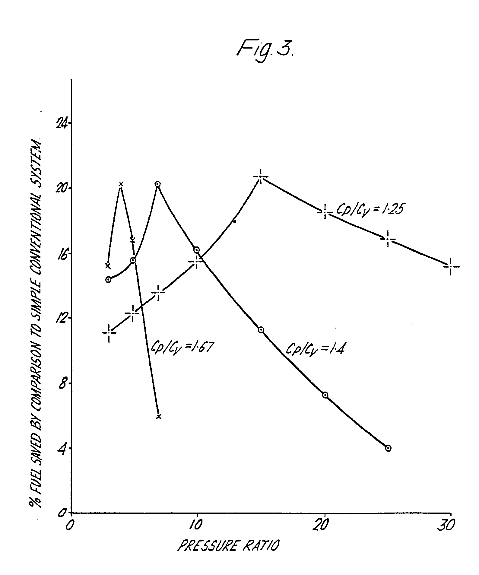
Figure 3 is a graph showing the percentage of fuel which can be saved according to
the pressure ratio used and the ratio of the (Cp/Cv) of the gas being compressed.
[0021] Referring to Figure 1 fuel from line 1 is mixed with air from line 2 and burnt. The
resulting hot gas is used to raise superheated steam at 900 psia (62 bars A) and 900°F
( 482°C) in boiler 3. The stack gas leaving boiler 3 is used to reheat the air in
line 2 as shown.
[0022] The superheated steam leaves boiler 3 through line 4 and is expanded to 0.7 psia
(0.05 bars A) through steam turbine 5 which it leaves through line 6 at 90°F (32.2°C)
The water vapour is then condensed against cooling water in condenser 7. It is then
deaerated in steam deaerator 14, repressurized by pump 8 and recycled to the boiler
3 via line 9 as shown.
[0023] The steam turbine 5 is mechanically coupled to air compressor 10 which has three
stages separated by water cooled intercoolers 11 and 12. The compressed air leaving
all three stages is cooled to 80°F(26.6°C).
[0024] Typically, the amount of fuel required in the apparatus described with reference
to Figure 1 to compress 218000 kg/hr of air from atmospheric pressure to 90.5 psia
(6.25 bar A) (for example for a 1130 MT/d oxygen plant) is 149.1 x 10
B BTU/Hr. (43,700 kW).
[0025] Referring to Figure 2, fuel from line 101 is mixed with air from line 102 and burnt.
The resulting hot gas is used to raise superheated steam at 900 psia (62 bars A) and
900°F (482°C) in boiler 103. The stack gas leaving boiler 103 is used to pre-heat
the air in line 102 as shown. The stack gas exit temperature is the same in both Figures.
[0026] The superheated steam leaves boiler 103 through line 104 and is expanded to 0.7 psia
(0.05 bars A) through steam turbine 105 which it leaves through line 106 at 90°F (32.2°C).
The water vapour is then condensed in condenser 107. It is then deaerated in vacuum
deaerator 114, repressurized by pump 108, preheated to 494°F (257°C) in heat exchanger
120 and recycled to the boiler 103 via line 109 as shown.
[0027] The steam turbine 105 is mechanically coupled to air compressor 110 which has a single
casing with no intercoolers (i.e. a substantially adiabatic compressor) and a pressure
ratio of (92.2/14.2) = 6.3:1. The air enters the air compressor 110 through conduit
111 and leaves through conduit 112 at 92.2 psia (6.36 bars A) and 511°F (266°C). The
hot air is then cooled to 125°F (51.7°C) in heat exchanger 120 before being cooled
to 80°F (26.7°C) in cooler 113.
[0028] The amount of fuel required in the apparatus described with reference to Figure 2
to compress 218000 Kg/hrofairfrom ambient to 90.5 psia (6.25 bars A) is 123.1 x 10
6 BTU/Hr (36,100 KW) which represents a fuel saving in excess of 17% over the embodiment
shown in Figure 1.
[0029] Figure 3 shows how the amount of fuel which can be saved depends on the ratio of
Cp/Cv of the gas. Thus for air, which has a Cp/Cv of approximately 1.4, the optimum
pressure ratio is 7: 1. lf it was desired, for example to compress airfrom 1 to 49
bars the preferred arrangement would be to compress the air from 1 to 7 bars generally
adiabatically, cool the exiting gas against coolant, compress the cooled gas from
7 to 49 bars generally adiabatically, and then cool the exiting gas against coolant.
Subject to a little fine tuning this arrangement will lead to the greatest fuel saving
compared with the prior art. In this connection it should be noted that the precise
optimum varies according to the adiabatic efficiency of the generally adiabatic compressor,
the isothermal efficiency of the prior art compressor against which it is being compared,
the precise ratio of Cp/ Cv of the gas in question at the pressure and temperature
in question, and the temperature and pressure of the steam. In most practical installations
we envisage that the pressure ratios used will lie in the ranges indicated hereinbefore.
It should perhaps be explained that in the embodiment shown in Figure 2 the 6.3:1
pressure ratio was used to achieve the operating pressure required in one of our standard
air separation plants.
[0030] Various modifications to the embodiments described with reference to Figure 2 are
envisaged. Thus, whilst in the preferred embodiment energy is directly returned to
the compressor via steam, it could also be returned to the compressor indirectly.
Thus, if the compressor were driven by an electric motorthe coolant could be used
to drive a generator-loaded turbine and the electricity generated returned to the
grid.
[0031] The generally adiabatic compressor for use in the present invention should have as
a high an adiabatic efficiency as possible. Although not essential it is recommended
that the adiabatic efficiency should be at least 75% and preferably greater than 83%.
1. A method of compressing gas, which method comprises the steps of compressing said
gas, cooling said compressed gas by heat exchange with a coolant, further heating
and vaporizing said coolant, and expanding said vaporized coolant through a turbine
to provide energy to compress said gas, characterised in that said gas has a Cp/Cv
ratio greater than 1.55 and is compressed in a substantially adiabatic mannerthrough
a pressure ratio between 2.5:1 and 8:1.
2. A method according to Claim 1, wherein said pressure ratio is between 3:1 and 7:1.
3. A method according to Claim 2. wherein said pressure ratio is 4:1.
4. A method of compressing gas, which method comprises the steps of compressing said
gas, cooling said compressed gas by heat exchange with a coolant, further heating
and vaporizing said coolant, and expanding said vaporized coolant through a turbine
to provide energy to compress said gas, characterised in that said gas has a Cp/Cv
ratio between 1.55 and 1.33 and is compressed in a substantially adiabatic mannerthrough
a pressure ratio between 4:1 and 30:1.
5. A method according to Claim 4, wherein said pressure ratio is between 4:1 and 20:1.
6. A method according to Claim 5, wherein said pressure ratio is 7:1.
7. A method of compressing gas, which method comprises the steps of compressing said
gas, cooling said compressed gas by heat exchange with a coolant, further heating
and vaporizing said coolant, and expanding said vaporized coolant through a turbine
to provide energy to compress said gas, characterised in that said gas has a Cp/Cv
ratio less than 1.33 and is compressed in a substantially adiabatic mannerthrough
a pressure ratio between 2.5:1 and 75:1.
8. A method according to Claim 7, wherein said pressure ratio is between 6:1 and 50:1.
9. A method according to any preceding Claim, wherein said compressed gas is cooled
by counter-current heat exchange with said coolant.
10. A method according to any preceding Claim, wherein said coolant is water under
super-atmospheric pressure.
11. A method according to Claim 10, wherein the steam formed by said further heating
is expanded through a steam turbine mechanically connected to said compressor.
12. A method according to Claim 11, wherein said water is at a pressure substantially
equal to the pressure at the inlet of said steam turbine.
13. An apparatus for carrying out a method according to claim 1 which apparatus comprises
a compressor (110), a heat exchanger (120) in which heat from compressed gas can be
transferred to a coolant, means (103) for further heating and vaporizing said coolant,
and a turbine (105) in which said vaporized coolant can be expanded for recovering
at least part of the heat transferred to said coolant and using it to compress said
gas, characterised in that said compressor (110) is designed to compress said gas
substantially adiabatically through a pressure ratio of between 2.5:1 and 8:1 when
said gas has a Cp/Cv ratio greater than 1.55
14. An apparatus for carrying out a method according to claim 4 whch apparatus comprises
a compressor (110), a heat exchanger (120) in which heat from compressed gas can be
transferred to a coolant, means (103) for further heating and vaporizing said coolant,
and a turbine (105) in which said vaporized coolant can be expanded for recovering
at least part of the heat transferred to said coolant and using it to compress said
gas, characterised in that said compressor (110) is designed to compress said gas
substantially adiabatically through a pressure ratio of between 4:1 and 30:1 when
said gas has a Cp/Cv ratio between 1.55 and 1.33.
15. An apparatus for carrying out a method according to claim 7 which apparatus comprises
a compressor (110), a heat exchanger (120) in which heat from compressed gas can be
transferred to a coolant, means (103) for further heating and vaporizing said coolant,
and a turbine (105) in which said vaporized coolant can be expanded for recovering
at least part of the heat transferred to said coolant and using it to compress said
gas, characterised in that compressor (110) is designed to compress said gas substantially
adiabatically through a pressure ratio of between 2.5:1 and 75:1 when said gas has
a Cp/Cv ratio less than 1.33.
16. An apparatus as claimed in Claim 14, 15 or 16, wherein said heat exchanger (120)
is arranged to bring compressed gas from said compressor (110) into counter-current
heat exchange with said coolant.
17. An apparatus as claimed in Claim 13,14,15 or 16, wherein said means for further
heating and vaporizing said coolant comprises a boiler.
18. An apparatus as claimed in any of Claims 13 to 17 wherein said coolant is water.
19. An air separation plant comprising an apparatus according to any of Claims 13
to 18.
20. An ammonia synthesis plant comprising an apparatus according to any of Claims
13 to 18.
21. An ethylene plant comprising an apparatus according to any of Claims 13 to 18.
22. A natural gas compression plant comprising an apparatus according to any of Claims
13 to 18.
23. A natural gas liquifaction plant comprising an apparatus according to any of Claims
13 to 18.
24. A methanol plant comprising an apparatus according to any of Claims 13 to 18.
25. A urea synthesis plant comprising an apparatus according to any of Claims 13 to
18.
1. Verfahren zur Gasverdichtung, wobei dieses Verfahren die Schritte der Verdichtung
dieses Gases, der Abkühlung des verdichteten Gases durch Wärmeaustausch mit einem
Kühlmittel, des weiteren Erwärmens und Verdampfens dieses Kühlmittels und des Expandierens
dieses verdampften Kühlmittels durch eine Turbine umfaßt, um Energie zur Verdichtung
dieses Gases zu liefern, dadurch gekennzeichnet, daß dieses Gas ein Verhältnis Cp/Cv
von größer als 1,55 aufweist und durch ein Druckverhältnis zwischen 2,5:1 und 8:1
auf eine im wesentlichen adiabatische Weise verdichtet wird.
2. Verfahren nach Anspruch 1, worin das Druckverhältnis zwischen 3:1 und 7:1 liegt.
3. Verfahren nach Anspruch 2, worin das Druckverhältnis 4:1 beträgt.
4. Verfahren zur Gasverdichtung, wobei dieses Verfahren die Schritte der Verdichtung
des Gases, der Abkühlung des verdichteten Gases durch Wärmeaustausch mit einem Kühlmittel,
des weiteren Erwärmens und Verdampfens des Kühlmittels und des Expandierens des verdampften
Kühlmittels durch eine Turbine umfaßt, um Energie zur Verdichtung des Gases zu liefern,
dadurch gekennzeichnet, daß dieses Gas ein Verhältnis Cp/Cv zwischen 1,55 und 133
aufweist und durch ein Druckverhältnis zwischen 4:1 und 30:1 auf eine im wesentlichen
adiabatische Weise verdichtet wird.
5. Verfahren nach Anspruch 4, worin das Druckverhältnis zwischen 4:1 und 20:1 liegt.
6. Verfahren nach Anspruch 5, worin das Druckverhältnis 7:1 beträgt.
7. Verfahren zur Gasverdichtung, wobei dieses Verfahren die Schritte der Verdichtung
dieses Gases, der Abkühlung dieses verdichteten Gases durch Wärmeaustausch mit einem
Kühlmittel, des weiteren Erwärmens und Verdampfens des Kühlmittels und des Expandierens
dieses verdampften Kühlmittels durch eine Turbine umfaßt, um Energie zur Verdichtung
des Gases zu liefern, dadurch gekennzeichnet, daß dieses Gas ein Verhältnis Cp/Cv
von kleiner als 1,33 aufweist und durch ein Druckverhältnis zwischen 2,5:1 und 75:1
auf eine im wesentlichen adiabatische Weise verdichtet wird.
8. Verfahren nach Anspruch 7, worin das Druckverhältnis zwischen 6:1 und 50:1 liegt.
9. Verfahren nach einem der vorstehenden Ansprüche, worin das verdichtete Gas durch
Gegenstromwärmeaustausch mit dem Kühlmittel abgekühlt wird.
10. Verfahren nach einem der vorstehenden Ansprüche, worin das Kühlmittel Wasser mit
Überdruck ist.
11. Verfahren nach Anspruch 10, worin der durch das weitere Erwärmen gebildete Dampf
durch eine Dampfturbine expandiert wird, die mechanisch an den Kompressor verbunden
ist.
12. Verfahren nach Anspruch 11, worin das Wasser einen Druck aufweist, der im wesentlichen
dem Druck am Einlaß der Dampfturbine gleich ist.
13. Vorrichtung zur Durchführung des Verfahrens nach Anspruch 1, wobei diese Vorrichtung
einen Kompressor (110), einen Wärmeaustauscher (120), in dem Wärme vom verdichteten
Gas auf das Kühlmittel übertragen werden kann, eine Einrichtung (103) zum weiteren
Erwärmen und Verdampfen des Kühlmittels und eine Turbine (105) umfaßt, in der das
verdampfte Kühlmittel zur Rückgewinnung zumindest eines Teils der auf das Kühlmittel
übertragenen Wärme expandiert werden kann und diese zur Verdichtung des Gases verwendet
wird, dadurch gekennzeichnet, daß der Kompressor (110) so gestaltet ist, daß er das
Gas durch ein Druckverhältnis von zwischen 2,5:1 und 8:1 im wesentlichen adiabatisch
verdichtet, wenn dieses Gas ein Verhältnis Cp/Cv von größer als 1,55 aufweist.
14. Vorrichtung zur Durchführung des Verfahrens nach Anspruch 4, wobei diese Vorrichtung
einen Kompressor (110), einen Wärmeaustauscher (120), in dem Wärme vom verdichteten
Gas auf das Kühlmittel übertragen werden kann, eine Einrichtung (103) zum weiteren
Erwärmen und Verdampfen des Kühlmittels und eine Turbine (105) umfaßt, in der das
verdampfte Kühlmittel zur Rückgewinnung zumindest eines Teils der auf das Kühlmittel
übertragenen Wärme expandiert werden kann und diese zur Verdichtung des Gases verwendet
wird, dadurch gekennzeichnet, daß der Kompressor (110) so gestaltet ist, daß er dieses
Gas durch ein Druckverhältnis von zwischen 4:1 und 30:1 im wesentlichen adiabatisch
verdichtet, wenn das Gas ein Verhältnis Cp/ Cv zwischen 1,55 und 1,33 aufweist.
15. Vorrichtung zur Durchführung des Verfahrens nach Anspruch 7, wobei diese Vorrichtung
einen Kompressor (110), einen Wärmeaustauscher (120), in dem Wärme vom verdichteten
Gas auf das Kühlmittel übertragen werden kann, eine Einrichtung (103) zum weiteren
Erwärmen und Verdampfen des Kühlmittels und eine Turbine (105) umfaßt, in der das
verdampfte Kühlmittel zur Rückgewinnung zumindest eines Teils der auf das Kühlmittel
übertragenen Wärme expandiert werden kann und diese zur Verdichtung des Gases verwendet
wird, dadurch gekennzeichnet, daß der Kompressor (110) so gestaltet ist, daß er das
Gas durch ein Druckverhältnis zwischen 2,5:1 und 75:1 im wesentlichen adiabatisch
verdichtet, wenn dieses Gas ein Verhältnis Cp/Cv von kleiner als 1,33 aufweist.
16. Vorrichtung nach Anspruch 14, 15 oder 16, worin der Wärmeaustauscher (120) angeordnet
ist, um das verdichtete Gas aus dem Kompressor (110) in Gegenstromwärmeaustausch mit
dem Kühlmittel zu bringen.
17. Vorrichtung nach Anspruch 13, 14, 15 oder 16, worin die Einrichtung zum weiteren
Erwärmen und Verdampfen des Kühlmittels einen Kessel umfaßt.
18. Vorrichtung nach einem der Ansprüche 13 bis 17, worin das Kühlmittel Wasser ist.
19. Anlage zur Lufttrennung, die eine Vorrichtung nach einem der Ansprüche 13 bis
18 umfaßt.
20. Anlage zur Ammoniaksynthese, die eine Vorrichtung nach einem der Ansprüche 13
bis 18 umfaßt.
21. Ethylenanlage, die eine Vorrichtung nach einem der Ansprüche 13 bis 18 umfaßt.
22. Verdichtungsanlage für Naturgas, die eine Vorrichtung nach einem der Ansprüche
13 bis 18 umfaßt
23. Anlage zur Verflüssigung von Naturgas, die eine Vorrichtung nach einem der Ansprüche
13 bis 18 umfaßt.
24. Methanolanlage, die eine Vorrichtung nach einem der Ansprüche 13 bis 18 umfaßt.
25. Anlage zur Harnstoffsynthese, die eine Vorrichtung nach einem der Ansprüche 13
bis 18 umfaßt.
1. Méthode pour comprimer un gaz, comprenant les étapes consistant à comprimer ledit
gaz, à refroidir ledit gaz comprimé par échange de chaleur avec un agent réfrigérant,
à chauffer en plus et vaporiser ledit agent réfrigérant, et à détendre ledit agent
réfrigérant vaporisé dans une turbine pour obtenir l'énergie permettant de comprimer
ledit gaz, caractérisée en ce que ledit gaz présente un rapport Cp/Cv supérieur à
1,55 et est comprimé d'une manière sensiblement adiabatique avec un rapport entre
les pressions compris entre 2,5:1 et 5:1.
2. Méthode selon la revendication 1, dans laquelle ledit rapport entre les pressions
est compris entre 3:1 et 7:1.
3. Méthode selon la revendication 2, dans laquelle ledit rapport entre les pression
est de 4:1.
4. Méthode pour comprimer un gaz, comprenant les étapes consistant à comprimer ledit
gaz, à refroidir ledit gaz comprimé par échange de chaleur avec un agent réfrigérant,
à chauffer en plus et vaporiser ledit agent réfrigérant, et à détendre ledit agent
réfrigérant vaporisé dans une turbine pour obtenir l'énergie permettant de comprimer
ledit gaz, caractérisée en ce que ledit gaz présente un rapport Cp/Cv compris entre
1,55 et 1,33 et est comprimé d'une manière sensiblement adiabatique avec un rapport
entre les pressions compris entre 4:1 et 30:1.
5. Méthode selon la revendication 4, dans laquelle ledit rapport entre les pressions
est compris entre 4:1 et 20:1.
6. Méthode selon la revendication 5, dans laquelle ledit rapport entre les pressions
est de 7:1.
7. Méthode pour comprimer un gaz, comprenant les étapes consistant à comprimer ledit
gaz, à refroidir ledit gaz comprimé par échange de chaleur avec un agent réfrigérant,
à chauffer en plus et vaporiser ledit agent réfrigérant, et à détendre ledit agent
réfrigérant vaporisé dans une turbine pour obtenir l'énergie permettant de comprimer
ledit gaz, caractérisée en ce que ledit gaz présente un rapport Cp/Cv inférieur à
1,33 et est comprimé d'une manière sensiblement adiabatique et selon un rapport entre
les pressions compris entre 2,5:1 et 75:1.
8. Méthode selon la revendication 7, dans laquelle ledit rapport entre les pressions
est compris entre 6:1 et 50:1.
9. Méthode selon l'une quelconque des revendications précédentes, dans laquelle ledit
gaz comprimé est refroidi par échange de chaleur à contre-courant avec ledit agent
réfrigérant.
10. Méthode selon l'une quelconque des revendications précédentes, dans laquelle ledit
agent réfrigérant est de l'eau à une pression supérieure à la pression atmosphérique.
11. Méthode selon la revendication 10, dans laquelle la vapeur formée par ledit chauffage
en plus est détendue par une turbine à vapeur connectée mécaniquement audit compresseur.
12. Méthode selon la revendication 11, dans laquelle ladite eau est une pression sensiblement
égale à la pression à l'entrée de ladite turbine à vapeur.
13. Dispositif pour mettre en oeuvre une méthode selon la revendication 1, comprenant
un compresseur (110), un échangeur de chaleur (120) dans lequel la chaleur provenant
du gaz comprimé peut être transmise à un agent réfrigérant, des moyens (103) pour
chauffer encore plus et vaporiser ledit agent réfrigérant, et une turbine (105) dans
laquelle ledit agent réfrigérant vaporisé peut être détendu pour récupérer au moins
une partie de la chaleur transmise audit agent réfrigérant et l'utiliser pour comprimer
ledit gaz, caractérisé en ce que ledit compresseur (110) est conçu pour comprimer
ledit gaz sensiblement adiabatiquement selon un rapport entre les pressions compris
entre 2,5:1 et 8:1 quand ledit gaz a un rapport Cp/Cv supérieur à 1,55.
14. Dispositif pour mettre en oeuvre une méthode selon la revendication 4, comprenant
un compresseur (110), un échangeur de chaleur (120) dans lequel la chaleur provenant
du gaz comprimé peut être transmise à un agent réfrigérant, des moyens (103) pour
chauffer encore plus et vaporiser ledit agent réfrigérant, et une turbine (105) dans
laquelle ledit agent réfrigérant vaporisé peut être détendu pour récupérer au moins
une partie de la chaleur transmise audit agent réfrigérant et l'utiliser pour comprimer
ledit gaz, caractérisé en ce que ledit compresseur (110) est conçu pour comprimer
ledit gaz sensiblement adiabatiquement selon un rapport entre les pressions compris
entre 4:1 et 30:1 quand ledit gaz a un rapport Cp/Cv compris entre 1,55 et 1,33.
15. Dispositif pour mettre en oeuvre une méthode selon la revendication 7, comprenant
un compresseur (110), un échangeur de chaleur (120) dans lequel la chaleur provenant
du gaz comprimé peut être transmise à un agent réfrigérant, des moyens (103) pour
chauffer encore plus et vaporiser ledit agent réfrigérant, et une turbine (105) dans
laquelle ledit agent réfrigérant vaporisé peut être détendu pour récupérer au moins
une partie de la chaleur transmise audit agent réfrigérant et l'utiliser pour comprimer
ledit gaz, caractérisé en ce que ledit compresseur (110) est conçu pour comprimer
ledit gaz sensiblement adiabatiquement selon un rapport entre les pressions compris
entre 2,5:1 et 75:1 quand ledit gaz a un rapport Cp/Cv inférieur à 1,33.
16. Dispositif selon la revendication 14, 15 ou 16, dans lequel ledit échangeur de
chaleur (120) est agencé pour diriger le gaz comprimé provenant dudit compresseur
(110) dans un échangeur de chaleur à contre-courant avec ledit agent réfrigérant.
17. Dispositif selon la revendication 13, 14, 15 ou 16, dans lequel lesdits moyens
pour chauffer en plus et vaporiser ledit agent réfrigérant sont constitués par une
chaudière.
18. Dispositif selon l'une quelconque des revendications 13 à 17, dans lequel ledit
agent réfrigérant est de l'eau.
19. Installation de séparation d'air comprenant un dispositif selon l'une quelconque
des revendications 13 à 18.
20. Installation de synthèse d'ammoniaque comprenant un dispositif selon l'une quelconque
des revendications 13 à 18.
21. Installation à éthylène comprenant un dispositif selon l'une quelconque des revendications
13 à 18.
22. Installation de compression de gaz naturel comprenant un dispositif selon l'une
quelconque des revendications 13 à 18.
23. Installation de liquéfaction de gaz naturel comprenant un dispositif selon l'une
quelconque des revendications 13 à 18.
24. Installation à méthanol comprenant un dispositif selon l'une quelconque des revendications
13 à 18.
25. Installation de synthèse d'urée comprenant un dispositif selon l'une quelconque
des revendications 13 à 18.