| (19) |
 |
|
(11) |
EP 0 077 208 B1 |
| (12) |
EUROPEAN PATENT SPECIFICATION |
| (45) |
Mention of the grant of the patent: |
|
16.01.1985 Bulletin 1985/03 |
| (22) |
Date of filing: 12.10.1982 |
|
|
| (54) |
Apparatus for intermittently dispensing a liquid additive into a flowing liquid stream
Vorrichtung zur intermittierenden Zugabe eines flüssigen Mittels in einen Flüssigkeitsstrom
Dispositif pour ajouter un additif liquide par intermittence à un courant liquide
|
| (84) |
Designated Contracting States: |
|
AT BE CH DE FR GB IT LI NL SE |
| (30) |
Priority: |
13.10.1981 US 310018
|
| (43) |
Date of publication of application: |
|
20.04.1983 Bulletin 1983/16 |
| (71) |
Applicant: Clow Corporation |
|
Jacksonville
Florida 32216 (US) |
|
| (72) |
Inventor: |
|
- Klepa, Peter P.
Los Angeles
California, 90066 (US)
|
| (74) |
Representative: Newby, John Ross et al |
|
JY & GW Johnson,
Kingsbourne House,
229-231 High Holborn
London WC1V 7DP
London WC1V 7DP (GB) |
|
| |
|
| Note: Within nine months from the publication of the mention of the grant of the European
patent, any person may give notice to the European Patent Office of opposition to
the European patent
granted. Notice of opposition shall be filed in a written reasoned statement. It shall
not be deemed to
have been filed until the opposition fee has been paid. (Art. 99(1) European Patent
Convention).
|
[0001] The invention relates to dispensing systems for providing an automatic discharge
of a chemical additive to a liquid stream. For example, it is often desirable to be
able to treat water streams associated with, for example, cooling towers, heat exchangers
or evaporative condensers, to control various problems such as microbiological fouling,
corrosion and accumulation of scale. Although very large installations often have
very sophisticated treatment systems and regularly scheduled maintenance, there are
many somewhat smaller systems which could operate without maintenance for a few weeks
to a few months if a relatively small quantity of an appropriate additive were fed
to the liquid stream flowing through them on a periodic basis during their hours of
operation.
[0002] Examples of prior art systems for dispensing chemical additives contained in solid
briquettes are found in US-A-3,430,823 as well as in US-A-3,385,483 and US-A-3,094,134.
Each of these known systems permits the lowest briquette in a stack of such briquettes
to be intermittently contacted and partially dissolved as the water level in a feed
chamber cyclically rises and is then emptied by a siphon tube. Although dispensing
systems based on the use of briquettes perform quite satisfactorily, the briquettes
are expensive to manufacture and restrict somewhat the ability to provide a wide range
of suitable chemical additives and the concentrations actually added to the liquid
stream. Additives in liquid form are more satisfactory in the latter respects, but
existing commercial dispensing systems utilize drip feeders which can be difficult
to adjust on start-up, which are relatively expensive, and which can become very difficult
to reuse if the feed bottle of liquid additive is allowed to empty completely so that
crystals of the additive or other solid deposits have a chance to form. Also, such
drip feeders are wasteful if they continue to meter additive when the unit whose liquid
flow is being treated is not operating. US-A-2,461,334 discloses a system for siphoning
a liquid treatment additive into a feed chamber, but appears to be quite sensitive
to changes in viscosity with temperature, and uses a tube to meter the desired amount
of additive chemical required.
[0003] The present invention seeks to provide an improved liquid additive dispensing apparatus
which will offer the advantages of the briquette-based feeders in dispensing the chemicals
only when needed while also offering the advantage of being able to utilize a large
variety of liquid chemicals which are not available in solid form, and which, being
liquid, are easier to package for use.
[0004] According to the present invention there is provided an apparatus for intermittently
dispensing a liquid additive into a liquid stream flowing through a feeder chamber,
which feeder chamber has an inlet for receiving said liquid stream and an outlet in
the form of a siphon tube which is positioned within the feeder chamber so as to intermittently
reduce the level of liquid in the feeder chamber when the level of the liquid therein
reaches a predetermined maximum elevation, said apparatus including mounting means
to support a container of liquid additive and an inverted U-shaped capillary siphon
tube to pass liquid additive from a container on the mounting means into the feeder
chamber, which is characterised in that valve means is provided on said container
having an actuating member extending into said feeder chamber; means is mounted in
said feeder chamber for actuating said actuating member of said valve means in response
to the liquid in said feeder chamber reaching, or at least closely approaching, said
predetermined maximum elevation; said valve means having a metering chamber sized
to contain substantially the quantity of liquid additive which is to be dispensed
upon each actuation of the actuating member; said metering chamber being selectively
sealed at its lower end by a sealing means which is controlled by said actuating member;
said metering chamber having its upper end in communication with the liquid additive
in said container by means of said inverted U-shaped capillary siphon tube, said capillary
siphon tube serving to slowly fill said metering chamber following each actuation
of the actuating member to empty the metering chamber.
[0005] In its preferred form, the valve means is a spring loaded ball which is actuated
by a float located in the feeder chamber. Since it may well be desirable to feed no
more than 1 ml (e.g. about 0.1 ml) of chemical additive at each actuation of the valve
means, the free volume in the metering chamber will be of this size and will be located
immediately above the ball. The tiny metering chamber communicates with the liquid
additive in the container by means of a small diameter, inverted U-shaped capillary
tube. In order to prevent crystallization of chemicals in the valve assembly when
the apparatus is not actuated for an extended period, the valve means is preferably
positioned so that a portion of the liquid in the feeder chamber will contact it each
time the valve means is actuated. The liquid flowing in the feeder chamber will flush
the dispensed chemical additive away from the flow openings in the valve means to
a sufficient extent that crystals or other solid deposits cannot form and produce
clogging.
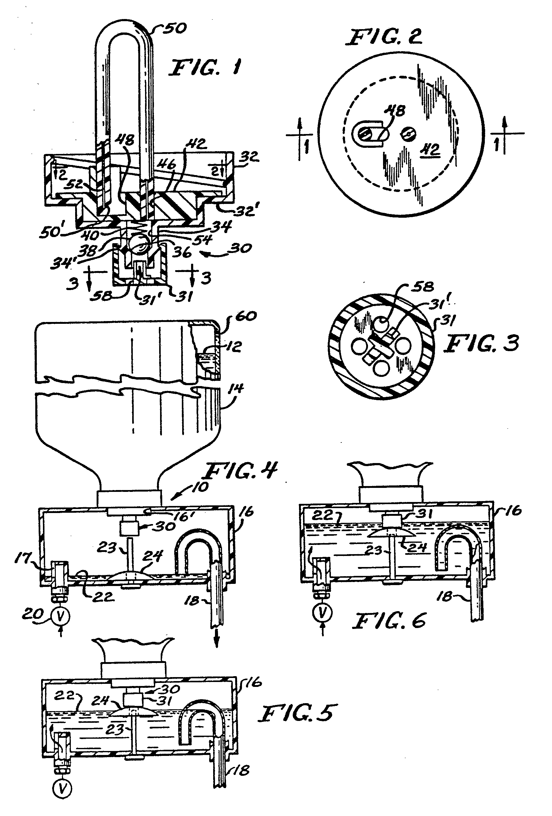
[0006] One embodiment of apparatus according to the invention will now be described, by
way of example, with reference to the accompanying drawing, in which
Figure 1 is a sectional side view of the closure and valve assembly of the apparatus
taken on the line 1-1 of Figure 2.
Figure 2 is a top sectional view taken on the line 2-2 of Figure 1,
Figure 3 is a sectional view taken on the line 3-3 of Figure 1, and
Figures 4 to 6 are partially sectioned side views of part of the apparatus showing
how the valve assembly of Figure 1 is employed to dispense a measured amount of a
liquid chemical into a feeder chamber.
[0007] The improved dispensing apparatus is indicated generally at 10 in Figure 4. The apparatus
dispenses a liquid chemical additive 12, contained in a container 14, into a feeder
chamber 16 which has an inlet port 17 and an outlet curved siphon tube 18. A valve
20 permits liquid 22, which is to be chemically treated, to pass through the inlet
port 17 into the feeder chamber 16 at an adjustably controlled rate. A guide pin 23,
which extends up from the bottom of the feeder chamber 16, acts as a guide for a float
24, which may be made of expanded foam or other suitable material: As the level of
liquid 22 commences to rise from its lowest level, as indicated in Figure 4, the float
24 will rise with it until it initially contacts a dispensing valve means 30, as indicated
in Figure 5. As additional liquid 22 enters the feeder chamber 16 at a rate exceeding
the rate of overflow through the siphon tube 18, the float 24 will rise further to
actuate a spring-biased actuating button 31 of the dispensing valve 30, as shown in
Figure 6. Naturally, the force of the valve actuating button 31 on the float 24 will
cause the level of the liquid 22 to rise more than the float. When the liquid level
rises sufficiently to completely fill the inverted U-portion of the siphon tube 18,
the siphon effect will be established in the tube 18 and the liquid in the feeder
chamber 16 will quickly drain back to the level shown in Figure 4.
[0008] The construction of the dispensing valve 30 is shown in Figures 1 to 3. The dispensing
valve 30 is mounted in a moulded cap 32 which can be attached by a screw thread, adhesive,
or other means to the container 14. The actuating button 31 is guided on a tubular
outer end portion 34 of the cap 32 and retained by an integral annular ring portion
34'. An internal shouldered ball seat 36 on the tubular portion 34 is engaged by a
sealing ball 38 which is forced against the seat 36 by a spring 40. The upper end
of the spring 40 engages a lower surface of a moulded insert member 42 which is secured
by adhesive or other means in the bottom of cap 32. The insert member 42 includes
a small circular aperture 46 and a larger slotted opening 48. The outlet end of a
plastics capillary siphon tube 50 having a capillary opening 52 is pressed tightly
into the aperture 46 while an angled inlet end 50' is supported in the slotted opening
48. The capillary siphon tube 50 serves to limit the number of drops of the chemical
12 that can be dispensed into a metering chamber 54 during the time that the ball
38 is lifted from its seat 36 by an actuator portion 31' of the actuating button 31
when the latter is lifted by the float 24. Thus, each filling cycle of the feeder
chamber 16 by the liquid 22 and the accompanying actuation of the dispensing valve
30 will cause a substantially constant amount of the chemical 12 to flow around the
ball 38 and down through openings 58 in the actuating button 31 into the liquid 22.
The dispensed quantity of chemical is substantially equal to the free volume of the
metering chamber 54 when the ball 38 is seated on its seat 36, the metering chamber
54 comprising the available volume inside the tubular outer end portion 34 between
the seat 36 and the underside of the insert member 42 which contains the capillary
siphon tube 50. Typically this available volume could be no more than 1 ml and could
be 0.1 ml or less.
[0009] To prevent any possibility that the dispensing openings 58 will become blocked from
drying and possible crystallization of the chemical 12 when there are long periods
in which liquid 22 is not flowing into the feeder chamber 16, the various elements
of the apparatus are preferably formed and positioned relative to each other so that
the level of liquid 22 will cover the openings 58 during the dispensing operation.
This relationship is apparent in Figure 6. Since chemical could not be dispensed for
long through a capillary tube from a rigid closed container 14, a small vent opening
60 is provided in the container 14 after it is inverted to its Figure 4 operative
use position. Although the means for mounting the container 14 on top of the feeder
chamber 16 is shown as an annular shoulder 32' on the cap 32 which rests on the periphery
of an opening 16' in the top of the feeder chamber 16, it is obvious that many other
forms of mounting connection could be used.
[0010] The apparatus illustrated could be used for many different applications, one being
the addition of a liquid water-conditioning agent into a recirculating water supply
for a refrigeration system.
1. An apparatus (10) for intermittently dispensing a liquid additive (12) into a liquid
stream (22) flowing through a feeder chamber (16), which feeder chamber (16) has an
inlet (17) for receiving said liquid stream (22) and an outlet in the form of a siphon
tube (18) which is positioned within the feeder chamber (16) so as to intermittently
reduce the level of the liquid (22) in the feeder chamber (16) when the level of the
liquid (22) therein reaches a predetermined maximum elevation, said apparatus including
mounting means (16', 32') to support a container (14) of liquid additive (12) and
an inverted U-shaped capillary siphon tube (50) to pass liquid additive (12) from
a container (14) on the mounting means (16', 32') into the feeder chamber (16), characterised
in that valve means (30) is provided on said container (14) having an actuating member
(31) extending into said feeder chamber (16); means (23, 24) is mounted in said feeder
chamber (16) for actuating said actuating member (31) of said valve means (30) in
response to the liquid (22) in said feeder chamber (16) reaching, or at least closely
approaching, said predetermined maximum elevation; said valve means (30) having a
metering chamber (54) sized to contain substantially the quantity of liquid additive
(12) which is to be dispensed upon each actuation of the actuating member (31); said
metering chamber (54) being selectively sealed at its lower end by a sealing means
(38, 34') which is controlled by said actuating member (31); said metering chamber
(54) having its upper end in communication with the liquid additive (12) in said container
(14) by means of said inverted U-shaped capillary siphon tube (50), said capillary
siphon tube (50) serving to slowly fill said metering chamber (54) following each
actuation of the actuating member (31) to empty the metering chamber (54).
2. Apparatus as claimed in claim 1, characterised in that said actuating portion (31)
of said valve means (30) includes openings (58) through which liquid additive (12)
from said metering chamber (54) can flow into the feeder chamber (16).
3. Apparatus as claimed in claim 2, characterised in that said openings (58) in said
actuating portion (31) are positioned within the feeder chamber (16) so as to be flushed
by the liquid (22) in the feeder chamber (16) as the level of said liquid (22) reaches
said predetermined maximum elevation.
4. Apparatus as claimed in any preceding claim, characterised in that said valve means
(30) is mounted in a cap (32) which normally seals an otherwise open-end of said container
(14) of liquid additive (12).
5. Apparatus as claimed in claim 4, characterised in that said cap (32) contains an
insert member (42) which includes a pair of apertures (46, 48) for retaining the ends
of said inverted U-shaped capillary tube (50), the outer end portion (34) of said
cap (32) being tubular in shape and including retaining means (34') for guiding and
retaining said actuating member (31).
6. Apparatus as claimed in claim 5, characterised in that said tubular outer end portion
(34) of said cap (32) includes an internal shouldered seat (36) which cooperates with
an internal ball (38) and a compression spring (40) to form said valve means (30),
said metering chamber (54) comprising the free volume of the internal portion of said
tubular outer end portion (34) which is located between said internal shouldered seat
(36) and the outlet end of said capillary siphon tube (50).
7. Apparatus as claimed in any preceding claim, characterised in that said means (23,
24) mounted in said feeder chamber (16) for actuating said valve means (30) comprises
a float (24).
8, Apparatus as claimed in claim 7, characterised in that the float (24) moves vertically
along a guide (23) to engage the actuating member (31) of said valve means (30) before
the liquid (22) in the feeder chamber (16) reaches said predetermined maximum elevation.
9. Apparatus as claimed in any preceding claim, characterised in that said valve means
(30) forms part of a cap (32) secured on the open top of a container (14) of liquid
additive (12), said container (14) then being inverted and supported with its gap
(32) lowermost on an upper surface of the feeder chamber (16).
10. Apparatus as claimed in any preceding claim, characterised in that the free volume
of the metering chamber does not exceed 1 ml.
1. Eine Vorrichtung (10) zur intermittierenden Zugabe eines flüssigen Mittels (12)
in einen Flüssigkeitsstrom (22), der eine Zugabekammer (16) durchströmt, wobei diese
Zugabekammer (16) einen Zulauf (17) zur Einleitung des genannten Flüssigkeitsstroms
(22) und einen Auslauf in Form eines Heberrohres (18) besitzt, das so innerhalb der
Zugabekammer (16) angeordnet ist, daß der Flüssigkeitsspiegel (22) in der Zugabekammer
(16) intermittierend verringert wird, wenn der dort vorhandene Flüssigkeitsspiegel
(22) ein vorbestimmtes Höchstniveau erreicht, wobei die genannte Vorrichtung Montagehalterungen
(16', 32') zur Aufnahme eines Behälters (14) für das flüssige Mittel (12) und ein
umgekehrt eingebautes, U-förmiges Heberkapillarrohr (50) zur Einleitung des flüssigen
Mittels (12) aus einem Behälter (14), der auf den Montagehalterungen (16', 32') ruht,
in die Zugabekammer (16) umfaßt, dadurch gekennzeichnet, daß eine Ventilvorrichtung
(30) am genannten Behälter (14) vorgesehen ist, deren Stellglied (31) in die genannte
Zugabekammer (16) hineinragt; die Vorrichtung (23, 24) in der genannten Zugabekammer
(16) zur Betätigung des genannten Stellglieds (31) der genannten Ventilvorrichtung
(30) dient, wenn die Flüssigkeit (22) in der genannten Zugabekammer (16) das vorbestimmte
Höchstniveau erreicht oder sich diesem zumindest nähert; die genannte Ventilvorrichtung
(30) eine Dosierkammer (54) von entsprechender Größe umfaßt, um im wesentlichen die
Menge des flüssigen Mittels (12) aufzunehmen, die bei jeder Betätigung des Stellglieds
(31) zugegeben werden muß, die genannte Dosierkammer (54) an ihrem unteren Ende zur
wahlweisen Absperrung eine Absperrvorrichtung (38, 34') besitzt, die über das genannte
Stellglied (31) gesteuert wird; die genannte Dosierkammer (54) mit ihrem oberen Ende
mit dem flüssigen Mittel (12) im genannten Behälter (14) über das genannte, umgekehrt
eingebaute, U-förmige Heberkapillarrohr (50) in Verbindung steht, wobei das genannte
Heberkapillarrohr (50) dazu dient, nach jeder erfolgten Betätigung des Stellglieds
(31) zur Leerung der Dosierkammer (54) die genannte Dosierkammer (54) langsam zu füllen.
2. Eine Vorrichtung gemäß Anspruch 1, dadurch gekennzeichnet, daß das genannte Stellglied
(31) der genannten Ventilvorrichtung (30) Öffnungen (58) umfaßt, durch die das flüssige
Mittel (12) aus der genannten Dosierkammer (54) in die Zugabekammer (16) fließen kann.
3. Eine Vorrichtung gemäß Anspruch 2,-dadurch gekennzeichnet, daß die genannten Öffnungen
(58) im genannten Stellglied (31) so innerhalb der Zugabekammer (16) angeordnet sind,
daß sie von der Flüssigkeit (22) in der Zugabekammer (16) durchspült werden, wenn
der Spiegel der genannten Flüssigkeit (22) das vorbestimmte Höchstniveau erreicht.
4. Eine Vorrichtung gemäß irgendeinem der vorgenannten Ansprüche, dadurch gekennzeichnet,
daß die genannte Ventilvorrichtung (30) von einer Haube (32) umgeben ist, die normalerweise
ein ansonsten offenes Ende des genannten Behälters (14) für das flüssige Mittel (12)
absperrt.
5. Eine Vorrichtung gemäß Anspruch 4, dadurch gekennzeichnet, daß die genannte Haube
(32) einen Einsatz (42) umfaßt, der Öffnungen (46, 48) zur Aufnahme der Enden des
genannten, umgekehrt eingebauten, U-förmigen Kapillarrohres (50) besitzt, wobei der
äußere Endabschnitt (34) der genannten Haube (32) rohrförmig ist und eine Haltevorrichtung
(34') zur Führung und Halterung des genannten Stellglieds (31) umfaßt.
6. Eine Vorrichtung gemäß Anspruch 5, dadurch gekennzeichnet, daß der genannte, rohrförmige,
äußere Endabschnitt (34) der genannten Haube (32) einen inneren, abgeschrägten Sitz
(36) hat, der zusammen mit einer innenliegenden Kugel (38) und einer Druck feder (40)
die genannte Ventilvorrichtung (30) bildet, wobei die genannte Dosierkammer (54) das
freie Volumen des inneren Teils des genannten rohrförmigen, äußeren Endabschnitts
(34) umfaßt, der zwischen dem genannten inneren, abgeschrägten Sitz (36) und dem Austrittsende
des genannten Heberkapillarrohres (50) angeordnet ist.
7. Eine Vorrichtung gemäß irgendeinem der vorgenannten Ansprüche, dadurch gekennzeichnet,
daß die gennante Vorrichtung (23, 24) in der genannten Zugabekammer (16) zur Betätigung
der genannten Ventilvorrichtung (30) eine Schwimmervorrichtung (24) umfaßt.
8. Eine Vorrichtung gemäß Anspruch 7, dadurch gekennzeichnet, daß sich die Schwimmervorrichtung
(24) vertikal entlang einer Führung (23) bewegt, um auf das Stellglied (31) der genannten
Ventilvorrichtung (30) einzuwirken, bevor die Flüssigkeit (22) in der Zugabekammer
(16) das vorbestimmte Höchstniveau erreicht.
9. Eine Vorrichtung gemäß irgendeinem der vorgennanten Ansprüche, dadurch gekennzeichnet,
daß die genannte Ventilvorrichtung (30) Bestandteil einer Haube (32) ist, die an der
oberen Öffnung eines Behälters (14) für das flüssige Mittel (12) befestigt ist, wobei
der genannte Behälter (14) dann umgekehrt wird, so daß er mit seiner Haube (32) zuunterst
auf der oberen Fläche der Zugabekammer (16) ruht.
10. Eine Vorrichtung gemäß irgendeinem der vorgenannten Ansprüche, dadurch gekennzeichnet,
daß das freie Volumen der Dosierkammer 1 ml nicht überschreitet.
1. Dispositif (10) ajouter par intermittence un additif liquide (12) à un courant
liquide (22) traversant une chambre d'alimentation (16), cette chambre d'alimentation
(16) présentant une entrée (17) pour recevoir ledit courant liquide (22) et une sortie,
sous forme d'un tube en siphon (18), disposé dans la chambre d'alimentation (16),
de manière à réduire, par intermittence, le niveau du liquide (22) dans la chambre
d'alimentation (16) lorsque le niveau du liquide (22) dans celle-ci approche une hauteur
maximale prédéterminée, ledit dispositif comprenant des supports (16', 32') pour supporter
un récipient (14) d'additif liquide (12) et un tube capillaire en forme de U renversé
(50) servant de siphon pour faire passer l'additif liquide (12) d'un récipient (14)
sur les supports (16', 32') dans la chambre d'alimentation (16), caractérisé en ce
qu'un dispositif à vanne (30) est prévu sur ledit récipient (14) pourvu d'un élément
de commande (31) s'étendant dans ladite chambre d'alimentation (16), l'élément (23,
24) est monté dans ladite chambre d'alimentation (16) pour actionner ledit élément
de commande (31) de ladite vanne (30) sous l'effet du liquide (22) dans ladite chambre
d'alimentation (16), qui atteint, ou du moins approche de très près, ladite hauteur
maximale prédéterminée ledit dispositif à vanne (30) presentant une chambre de dosage
(54), dimensionnée vanne (30) presentant une chambre de dosage (54), dimensionnée
de manière à contenir essentiellement la quantité d'additif liquide (12) qui doit
être ajoutée à chaque manoeuvre de l'élément de commande (31), ladite chambre de dosage
(54) étant fermée hermétiquement, d'une manière sélective, à son extrémité inférieure
par un dispositif de scellement (38, 54'), qui est commandé par ledit élément de commande
(31), ladite chambre de dosage (54) ayant son extrémité supérieure en communication
avec l'additif liquide (12) dans ledit récipient (14), au moyen dudit tube capillaire
en forme de U renversé (50) servant de siphon, ledit tube capillaire servant de siphon
(50) servant à remplir lentement ladite chambre de dosage (54) après chaque manoeuvre
de l'élément de commande (31) pour vider la chambre de dosage (54).
2. Dispositif selon la revendication 1, caractérisé en ce que ledit élément de commande
(31) dudit dispositif à vanne (30) comprend des ouvertures (58), par lesquelles l'additif
liquide (12), provenant de ladite chambre de dosage (54), peut s'écouler dans la chambre
d'alimentation (16).
3. Dispositif selon la revendication 2, caractérisé en ce que lesdites ouvertures
(58) dans ladite partie de commande (31), sont disposées dans la chambre d'alimentation
(16), de façon à être balayées par le liquide (22) dans la chambre d'alimentation
(16), lorsque le niveau dudit liquide (22) atteint ladite hauteur maximale prédéterminée.
4. Dispositif selon l'une des revendications précédentes, caractérisé en ce que ledit
dispositif à vanne (30) est montée dans une coiffe (32), qui ferme normalement, d'une
manière hermétique, une extrémité ouverte dudit récipient (14) d'additif liquide (12).
5. Dispositif selon la revendication 4, caractérisé en ce que ladite coiffe (32) contient
un élément inséré (42) qui comprend une paire d'ouvertures (46, 48) pour retenir les
extrémités dudit tube capillaire en forme de U renversé (50), la partie d'extrémité
extérieure (34) de ladite coiffe (32) ayant une forme tubulaire et comprenant un dispositif
de retenue (34') pour guider et retenir ledit élément de commande (31).
6. Dispositif selon la revendication 5, caractérisé en ce que ladite partie tubulaire
de l'extrémité extérieure (34) de ladite coiffe (32) comprend un siège intérieur à
épaulement (36), qui constitue ledit dispositif à vanne (40), en combinaison avec
une bille intérieure (38) et un ressort de compression (40), ladite chambre de dosage
(54) comprenant le volume libre de la partie intérieure de ladite partie tubulaire
de l'extrémité extérieure (34), qui est située entre ledit siège intérieur à épaulement
(36) et l'extrémité de sortie dudit tube capillaire (50) servant de siphon.
7. Dispositif selon l'une des revendications précédentes, caractérisé en ce que ledit
élément (23, 24), monté dans ladite chambre d'alimentation (16) pour actionner ledit
dispositif à vanne (30), comprend un flotteur (24).
8. Dispositif selon la revendication 7, caractérisé en ce que le flotteur (24) se
déplace verticalement le long d'un guide (23), de manière à venir au contact de l'élément
de commande (31) dudit dispositif à vanne (30), avant que le liquide (22) dans la
chambre d'alimentation (16) n'atteigne ladite hauteur maximum prédéterminée.
9. Dispositif selon l'une des revendications précédentes, caractérisé en ce que ledit
dispositif à vanne (30) fait partie d'une coiffe (32), fixée sur le sommet ouvert
d'un récipient (14) d'additif liquide (12), ledit récipient (14) étant ensuite renversé
et reposant, avec sa coiffe (32) dirigée vers le bas, sur une surface supérieure de
la chambre d'alimentation (16).
10. Dispositif selon l'une des revendications précédentes, caractérisé en ce que le
volume libre de la chambre de dosage ne dépasse pas 1 ml.