| (19) |
 |
|
(11) |
EP 0 111 355 B1 |
| (12) |
EUROPEAN PATENT SPECIFICATION |
| (45) |
Mention of the grant of the patent: |
|
09.04.1986 Bulletin 1986/15 |
| (22) |
Date of filing: 21.11.1983 |
|
| (51) |
International Patent Classification (IPC)4: B08B 15/02 |
|
| (54) |
Exhaust hood for a dipping plant
Abzugshaube für eine Tauchanlage
Hotte d'aspiration pour une installation d'immersion
|
| (84) |
Designated Contracting States: |
|
AT BE CH DE FR GB IT LI LU NL SE |
| (30) |
Priority: |
24.11.1982 NL 8204575
|
| (43) |
Date of publication of application: |
|
20.06.1984 Bulletin 1984/25 |
| (71) |
Applicant: CIC B.V. |
|
NL-6585 KD Mook (NL) |
|
| (72) |
Inventor: |
|
- Van der Veer, Johannes Hendrikus
NL-5853 AR Siebengewalt (gem. Bergen) (NL)
|
| (74) |
Representative: Konings, Lucien Marie Cornelis Joseph et al |
|
Arnold & Siedsma,
Advocaten en Octrooigemachtigden,
Sweelinckplein 1
2517 GK Den Haag
2517 GK Den Haag (NL) |
|
| |
|
| Note: Within nine months from the publication of the mention of the grant of the European
patent, any person may give notice to the European Patent Office of opposition to
the European patent
granted. Notice of opposition shall be filed in a written reasoned statement. It shall
not be deemed to
have been filed until the opposition fee has been paid. (Art. 99(1) European Patent
Convention).
|
[0001] The invention relates to an exhaust hood as defined in the preamble of claim 1.
[0002] Such a hood is known from FR-A-2 311 600 and FR-A-2 490 112.
[0003] When such an exhaust hood is used, in particular, in a zinc-plating plant, the known
exhaust hood removes much air from the zinc-plating plant in order to drain gases
set free during the zinc-plating process as much as possible. Therefore the acapacity
of the air removing means connected with the hood has to be correspondingly high.
This is particularly inconvenient when the air to be removed has to be filtered.
[0004] The invention provides an exhaust hood improved in this respect, which is characterized
as defined in claim 1. A further development of the exhaust hood embodying the invention
is described in claims 2 to 4.
[0005] The invention will now be described hereinafter with reference to a drawing.
[0006] This drawing schematically shows in the
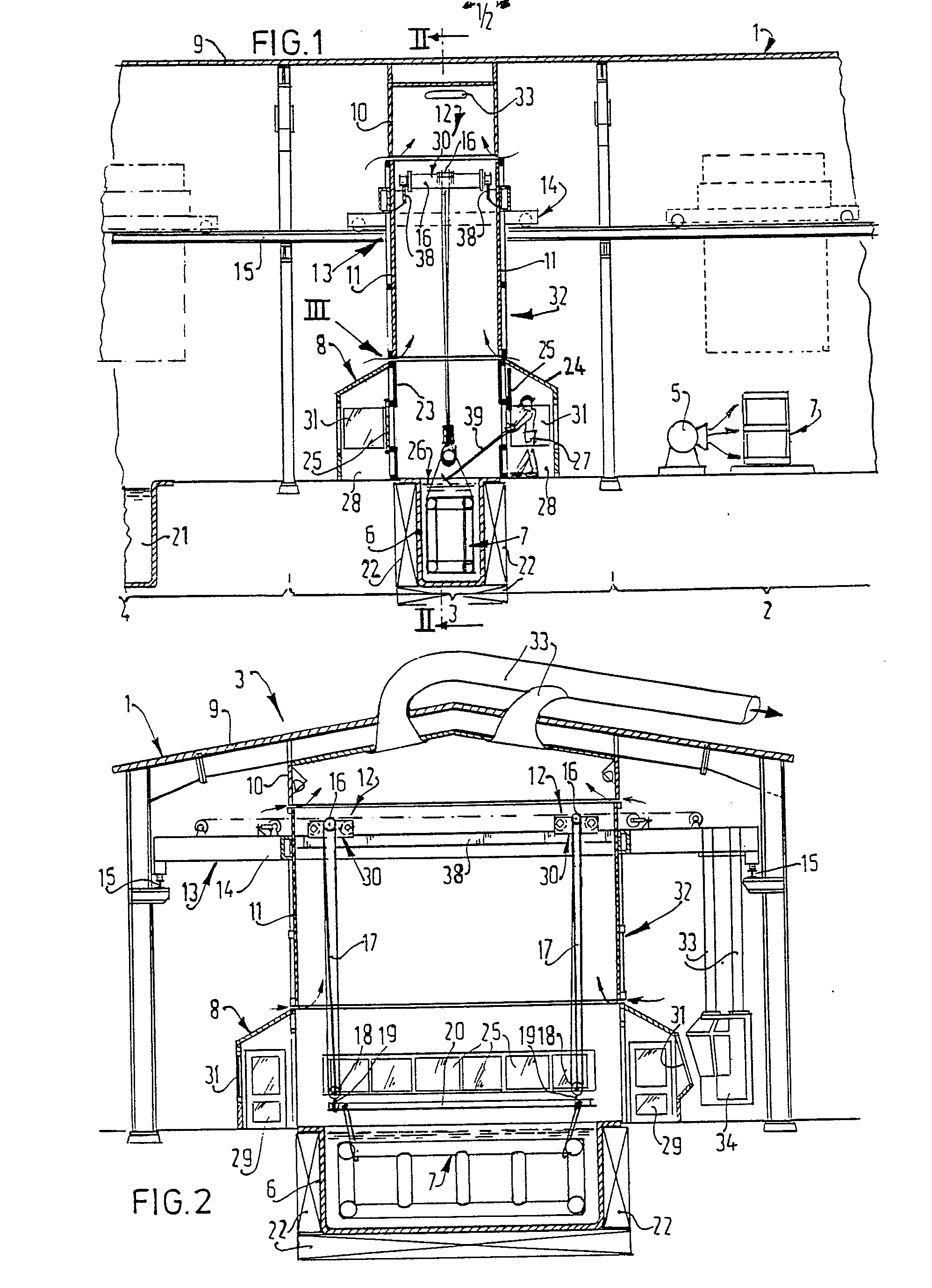
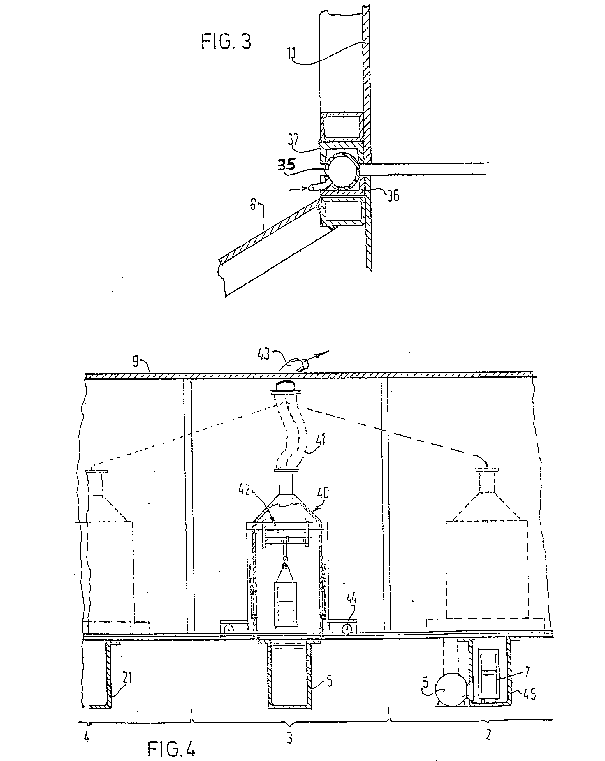
Figs. 1 and 4 longitudinal sectional views of part of a zinc-plating hall having relatively
different exhaust hoods embodying the invention,
Fig. 2 a sectional view taken on the line II-II in Fig. 1 and
Fig. 3 an enlarged sectional view of detail III in Fig. 1.
[0007] A zinc-plating hall 1 as shown in the Figs. 1 and 2 comprises a zinc-plating line
comprising in a conventional manner a degreasing bath, a plurality of pickling baths,
a flux bath, a drying station 2, a zinc-plating station 3 and a delivery station 4,
which is a cooling station. Fig. 1 only shows the latter three stations. At the drying
station 2 are provided the required drying means, for example, ventilators 5, which
dry the objects 7 preferably by hot air. At the zinc-plating station 3 the zinc-plating
bath 6 is provided with heating elements 22. This bath is surrounded by a stationary
lower hood element 8. Below the roof 9 of the hall 1 a stationary top hood element
10 is provided at the zinc-plating station 3. Between the lower and top hood elements
8 and 10 can be arranged a displaceable hood element 11 in which lifting means 12
of a lifting tool 13 are arranged.
[0008] The lifting tool 13 comprises a carriage 14 travelling on rails 15. To this carriage
14 is fastened the hood element 11, for example, by welding. The travelling crabs
30 of the lifting means 12 are movable along rails 38 of the carriage 14 arranged
in the interior of the hood element 11. Thae travelling crabs 30 are provided with
winches 16, lifting cables 17, pulleys 18, hooks 19 and a lifting frame 20 to which
the objects are fastened. The delivery station 4 is provided with a cooling bath 21.
[0009] The lower hood element 8 has an inner jacket 23 and an outer jacket 24, between which
a gallery is left, which is accessible through doors 29 to persons to scrape slags
with the aid of a scraper 39 from the surface 26 of the zinc-plating bath 6 immediately
before the zinc-plated objects 7 are lifted out of the zinc-plating bath.
[0010] The lower hood element 8 has, apart from transparent sash windows 25 further transparent
windows 31 in the outer jacket so that from the cabin 34 suspended by means of rods
33 to the carriage the crane driver can observe the manipulations of the objects 7.
[0011] At the drying station 2 and the cooling station 4 the crane driver can look below
the hood element 11.
[0012] The exhaust hood embodying the invention operates as follows:
The carriage 14 is driven with the hood element 11 towards the drying station. there
the lifting frame 20 is lowered, the objects 7 are fastened thereto and lifted together
with the lifting frame 20, so that the objects 7 are moved into the hood element 11.
Subsequently the carriage 14 drives towards the zinc-plating station 3, where the
displaceable hood element 11 completes an exhaust hood 32. The hood elements 8, 10
and 11 preferably adjoin one another with a small amount of play so that owing to
the subatmospheric pressure produced by ventilators (not shown) in the exhaust hood
32 developed gases and/or vapours are prevented from getting out of the exhaust hood
32 into the zinc-plating hall 1. The lifting frame 20 is lowered with the objects
7 and the objects 7 are dipped in the zinc-plating bath. The rising gases and/or vapours
are conducted away through outlet channels 33 from the top of hood element 10 either
directly or through filters into the open air. The hood elements 8, 10 and 11 are
preferably in sealing relationship with one another by means of a sealing strip 35,
which is formed as shown in Fig. 3 by an inflatable hose arranged between edges 36
and 37 of the hood elements 8 and 11, and 11 and 10 respectively.
[0013] When the zinc-plating process has terminated and practically no gases and/or vapours
are any longer produced, the sash windows 25 are lifted for scraping slags. Then the
zinc-plated objects 7 are lifted from the zinc-plating bath 6. the inflatable sealing
strip, if any, is in the meantime exhausted. The objects 7 together with the hood
element 11 are brought to the delivery station 4, where they are moved out of the
hood element 11 and unhooked from the lifting frame 20. Finally the lifting tool is
driven back to the drying station 2 for treating further objects 7.
[0014] In the variant of Fig. 4 the exhaust hood is an integral unit. Inside the hood 40
are arranged the lifting means 42. The exhaust hood 40 communicates through a hose
41 with an outlet channel 43 so that the exhaust hood 40 can move between the drying
station 2 and the delivery station 4, for example, since it is arranged on a carriage
44. The objects 7 are then located at the drying station 2 in a cellar 45.
[0015] With these exhaust hoods 32 and 40 and by the method described above it is satisfactorily
possible to zinc-plate objects 7 with baths arranged parallel side by side, the transport
paths between them being short.
1. An exhaust hood (32, 40) for a dipping plant, in particular a zinc-plating plant
(1), said plant comprising at least one bath (6) with a liquid for dipping articles
(7) top be treated therein, said exhaust hood (32, 40) comprising at least one displaceable
hood element (11, 40) carried by a carriage (14) of a lifting tool (13) said hood
element being movable by means of said carriage (14) to and from a position above
said bath (6), said hood element (11, 40) enclosing at least one motive power unit
(12) for a lifting apparatus (17, 18, 19), characterized in that the entire edge of
the displaceable hood element (11, 40) in its position above said bath (6) is contiguous
to and facing the entire circumference of a stationery part of the dipping plant,
said stationary part surrounding said bath (6).
2. An exhaust hood (32) as claimed in claim 1, characterized in that the exhaust hood
(32) comprise a stationary lower hood element (8), a stationary top hood element (10)
and a displaceable hood element (11) positionable in contiguous relationship between
the former in its position above said bath (6).
3. An exhaust hood as claimed in claim 1, characterized in that a flexible hose (41)
connects the top of said displaceable hood part (40) with a stationary outlet element
(43).
4. An exhaust hood (32) as claimed in any one of the preceding claims, characterized
in that at least one edge (36, 37) of a hood element is provided with a sealing strip
(35) for sealing the contiguous parts of the displaceable hood element and stationary
parts of the exhaust hood of the dipping plant.
5. An exhaust hood (32) as claimed in claim 4, characterized in that the sealing strip
(35) is an inflatable hose.
1. Abzugshaube (32, 40) für eine Tauchanlage, insbesondere eine Verzinkungsanlage
(1), wobei die Anlage zumindest ein Bad (6) mit einer Flüssigheit zum Eintauchen von
darin zu behandelnden Gegenständen (7) aufweist, wobei die Abzugshaube (32, 40) zumindest
ein verschiebbares Haubenteil (11, 40) aufweist, das von einem Wagen (14) eines Hebezeugs
(13) getragen ist, mittels dieses Wagens (14) in eine und aus einer Position über
dem Bad (6) bewegbar ist und mindestens eine bewegliche Antriebseinheit (12) für eine
Hubvorrichtung (17, 18, 19) einschließt, dadurch gekennzeichnet, daß der gesamte Rand
des verschiebbaren Haubenteils (11, 40) in seiner Position über dem Bad (6) benachbart
und zugewandt ist dem gesamten Umfang eines stationären Teils der Tauchanlage, wobei
dieser stationäre Teil das Bad (6) umgibt.
2. Abzugshaube (32) wie in Anspruch 1 beansprucht, dadurch gekennzeichnet, daß die
Abzugshaube (32) ein stationäres unteres Haubenteil (8), ein stationäres oberes Haubenteil
(10) und ein verschiebbares Haubenteil (11) aufweist, das in seiner Stellung über
dem Bad (6) angrenzend zwischen den vorerwähnten Teilen positionierbar ist.
3. Abzugshaube wie in Anspruch 1 beansprucht, dadurch gekennzeichnet, daß ein flexibler
Schlauch (41) das obere Ende des verschiebbaren Haubenteils (40) mit einem stationären
Auslaßelement (43) verbindet.
4. Abzugshaube (32) wie in einem der vorhergehenden Ansprüche beansprucht, dadurch
gekennzeichnet, daß zumindest ein Rand (36, 37) eines Haubenteils mit einem Dichtstreifen
(35) zum Abdichten der benachbarten Teile des verschiebbaren Haubenteils und der stationären
Teile der Abzugshaube der Tauchanlage versehen ist.
5. Abzugshaube (32) wie in Anspruch 4 beansprucht, dadurch gekennzeichnet, daß der
Dichtstreifen (35) ein aufblasbarer Schlauch ist.
1. Hotte d'aspiration (32, 40) pour une installation d'immersion, en particulier une
installation de galvanisation (1), ladite installation comprenant au moins un bain
(6) avec un liquide pour immerger des articles (7) qui doivent y être traités, ladite
hotte d'aspiration (32, 40) comprenant au moins un élément de hotte mobile (11, 40)
porté par un chariot (14) d'un équipement de levage (13), ledit élément de hotte étant
déplaçable au moyen dudit chariot (14) vers une position au-dessus dudit bain (6)
et en provenance de cette position, ledit élément de hotte (11, 40) entourant au moins
une unité motrice (12) d'un appareil de levage (17, 18, 19), caractérisée en ce que
la totalité du bord de l'élément de hotte mobile (11, 40), dans sa position au-dessus
dudit bain (6), est contigüe à une partie fixe de l'installation d'immersion, et en
regard de la totalité de la périphérie de cette partie fixe, ladite partie fixe entourant
ledit bain (6).
2. Hotte d'aspiration (32) selon la revendication 1, caractérisée en ce que la hotte
d'aspiration (32) comprend un élément de hotte inférieur fixe (8), un élément de hotte
supérieur fixe (10) et un élément de hotte mobile (11), pouvant être placés en relation
de contiguïté entre les premières, dans sa position au-dessus dudit bain (6).
3. Hotte d'aspiration selon la revendication 1, caractérisée en ce qu'un tuyau flexible
(41) relie la partie supérieure da ladite partie de hotte mobile (40) à un élément
d'évacution fixe (43).
4. Hotte d'aspiration (32) selon l'une quelconque des revendications précédentes,
caractérisée en ce qu'au moins un bord (36), 37) d'un élément de hotte esty pourvu
d'une bande d'etan- chéité (35) pour assurer l'étanchéité des parties contiguës de
l'élément de hotte mobile et des parties fixes de la hotte d'aspiration de l'installation
d'immersion.
5. Hotte d'aspiration (32) selon la revendication 4, caractérisée en ce que la bande
d'étanchéité (35) est un tuyau flexible gonflable.