| (19) |
 |
|
(11) |
EP 0 140 477 B1 |
| (12) |
EUROPEAN PATENT SPECIFICATION |
| (45) |
Mention of the grant of the patent: |
|
04.05.1988 Bulletin 1988/18 |
| (22) |
Date of filing: 16.07.1984 |
|
|
| (54) |
Air swirl nozzle
Luftdralldüse
Buse de turbulence d'air
|
| (84) |
Designated Contracting States: |
|
DE GB |
| (30) |
Priority: |
20.07.1983 US 516006
|
| (43) |
Date of publication of application: |
|
08.05.1985 Bulletin 1985/19 |
| (73) |
Proprietor: PARKER HANNIFIN CORPORATION |
|
Cleveland
Ohio 44112 (US) |
|
| (72) |
Inventors: |
|
- Simmons, Harold C.
Richmond Heights
Ohio 44143 (US)
- Harding, Curtis F.
Parma
Ohio 44134 (US)
|
| (74) |
Representative: Purvis, William Michael Cameron et al |
|
D. Young & Co.,
21 New Fetter Lane
London EC4A 1DA
London EC4A 1DA (GB) |
| (56) |
References cited: :
US-A- 2 010 403
US-A- 4 221 558
|
US-A- 3 980 233
|
|
| |
|
|
|
|
| |
|
| Note: Within nine months from the publication of the mention of the grant of the European
patent, any person may give notice to the European Patent Office of opposition to
the European patent
granted. Notice of opposition shall be filed in a written reasoned statement. It shall
not be deemed to
have been filed until the opposition fee has been paid. (Art. 99(1) European Patent
Convention).
|
[0001] The invention relates to nozzles for providing a controlled spray pattern and, more
particularly, to fuel nozzles for providing atomized fuel to a combustion chamber.
[0002] Various kinds of fuel nozzles are known, for example, pressure atomizer nozzles for
producing a spray pattern by passing the fuel through an orifice under pressure. Another
kind of fuel nozzle is the prefilming type nozzle wherein fuel is swirled in an annular
passage before it is mixed with air. One example of this kind of nozzle is shown in
US-A-3,980,233 to Simmons, et al.
[0003] Some recent applications for fuel nozzles require intermittent operation for spraying
volumes of fuel that are relatively small in comparison to prior art applications.
For example, in some recent applications, nozzles must operate at fuel flow rates
approximately ten times less than flow rates typical for aircraft application.
[0004] Downsizing prior art nozzles to accommodate these lower fuel flow rates has presented
a variety of problems. For example, the relatively small orifices of the downsized
nozzles are difficult to make and are subject to being plugged with particulate contaminants
in the fuel. Guarding the fuel orifices with low micron rated filters is costly and
inconvenient due to the frequent servicing requirements.
[0005] Because of the low fuel flow requirements, merely increasing the size of the fuel
orifices so that particulate contaminants would pass through the orifices, does not
permit sufficient fuel velocity to produce an acceptable spray pattern since under
such conditions pressure atomizer nozzles simply do not atomize and prefilming air-blast
nozzles do not prefilm the fuel, resulting in poor atomization and fuel distribution.
Moreover, in some nozzles the angle of the spray pattern is partially dependent on
the fuel flow rate and decrease in fuel flow rate produces unacceptable changes in
the spray pattern angle.
[0006] Patent Specification US-A-4 221 558 discloses a nozzle mounted within an outer housing,
the nozzle having a fuel feed thereto and exit ports angled to the longitudinal axis.
A collar around the nozzle defines an inner annular passage therewith and tangential
slots fed by the inner annular passage have the ports opening thereinto. Angled fins
in an outer annular passage connect the collar to the outer housing. In use liquid
fuel exiting from the ports is atomised by gaseous fuel fed to the inner annular passage
and is mixed with combustion air fed through the outer annular passage and swirled
by the fins.
[0007] There is a requirement for a smaller, reliable nozzle that will produce a desirable
spray pattern at low fuel flow rates.
[0008] According to the invention there is provided a nozzle comprising:
a housing;
a nozzle body engaging the housing and co-operating therewith to form an air chamber,
the nozzle body having at least one fuel chamber and at least one fuel orifice that
communicates with the fuel chamber through a fuel passageway substantially aligned
on an axis that intersects the longitudinal centre axis of the body; and
a swirl cone located between the housing and the body, the swirl cone co-operating
with the body to form an inner annulus with the fuel orifice included therein and
co-operating with the housing to form an outer annulus; characterised by a plurality
of vanes connected to the body and the swirl cone, the vanes being located between
the air chamber and the inner annulus, being canted with respect to the longitudinal
centre axis and being connected to the body at a greater radius from the centre axis
than the fuel orifice.
[0009] Thus the vanes provide an air swirl adjacent the fuel orifices.
[0010] Preferably, the swirl cone further includes a plurality of air passageways that communicate
between the air chamber and the outer annulus, each of the air passageways being tangentially
aligned with respect to the longitudinal centre axis of the nozzle.
[0011] The nozzle may include a cover that receives and co-operates with the housing to
form an annular cavity that communicates with the air chamber through an input channel.
[0012] The invention is diagrammatically illustrated by way of example with reference to
the accompanying drawings, in which:-
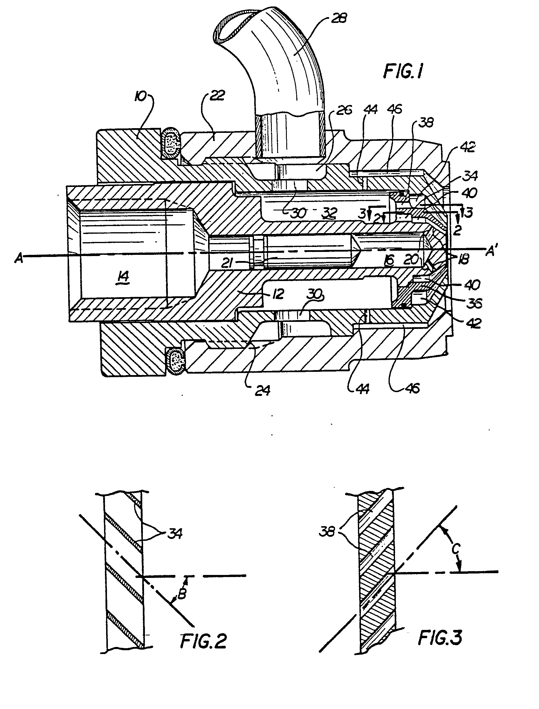
Figure 1 is a cross-section of a preferred embodiment of a nozzle according to the
invention;
Figure 2 is a partial section of the nozzle of Figure 1 taken on line 2-2 of Figure
1;
Figure 3 is a partial section of the nozzle of Figure 1 taken on line 3-3 of Figure
1;
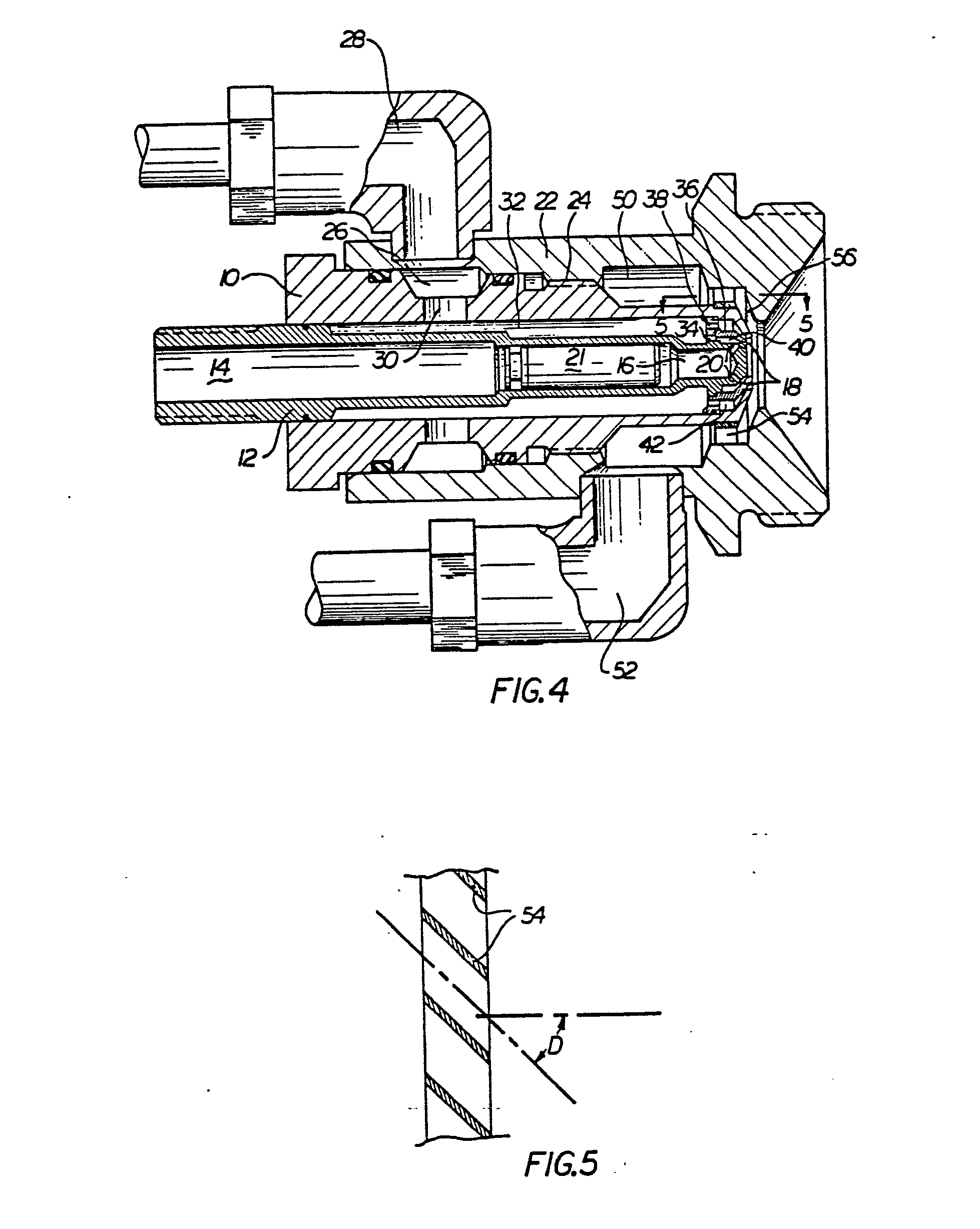
Figure 4 is a cross-section of an alternative embodiment of a nozzle according to
the invention; and
Figure 5 is a partial section of the nozzle of Figure 4 taken on line 5-5 of Figure
4.
[0013] Referring to Figures 1 to 3, a nozzle includes a housing 10 that is provided with
a central cavity wherein a nozzle body 12 is engaged. The body 12 is provided with
first and second fuel chambers 14 and 16 respectively located in tandem arrangement.
The second fuel chamber 16 has a smaller cross-sectional area than the first fuel
chamber 14 and communicates with fuel orifices 18 through respective fuel passages
20 provided at one end of the nozzle body 12. Each of the fuel passages 20 is radially
arranged with respect to the longitudinal centre axis A-A' of the body 12 such that
each of the fuel passages 20 is substantially aligned on a respective axis that intersects
the longitudinal centre axis. A check valve 21 is included in the fuel chamber 16.
[0014] A cover 22 is connected to the outside of the housing 10 by threads 24. An annular
channel is longitudinally located in the housing 10 adjacent an air supply hose 28
and co-operates with the internal surface of the cover 22 to form an air supply cavity
26. A plurality of ports 30 are provided in the base of the cavity 26 to provide communication
between the cavity 26 and an air chamber 32 formed between the housing 10 and the
nozzle body 12.
[0015] Swirl vanes 34 are attached to the nozzle body 12 adjacent the fuel orifices 18,
the vanes 34 being located between the air chamber 32 and the fuel orifices 18 and
being at a greater radial distance from the longitudinal axis A-A' than the fuel orifices
18. The vanes 34 support a swirl cone 36 that is concentrically arranged with respect
to the body 12. The swirl cone 36 is connected concentrically to the nozzle body 12
and co-operates with the nozzle body 12 to define an inner annulus 40 and co-operates
with the housing 10 to define an outer annulus 42. As can be seen in Figure 2, the
swirl vanes 34 are angularly arranged, or canted, at an angle B with respect to the
longitudinal axis A-A' such that air flowing from the chamber 32 past the vanes 34
to the inner annulus 40 assumes a swirling flow pattern downstream of the vanes 34.
[0016] The swirl cone 36 is provided with a plurality of passageways 38 that are angularly
arranged with respect to the longitudinal axis A-A' at an angle C such that each of
the passageways 38 is aligned on a respective axis that lies in a plane parallel to
the centre axis. Thus, air flowing from the chamber 32 through the passageways 38
to the outer annulus 42 develops a swirl pattern. Preferably, the passageways 38 are
arranged in the opposite sense to the angular arrangement to the vanes 32 so that
air downstream of the passageways 38 in the outer annulus 42 is swirled in counter-rotation
to air downstream of the vanes 34 in the inner annulus 40. Alternatively, for applications
in which swirled air in the outer annulus 40 is not required, the passageways 38 can
be aligned on respective axes that are parallel to the centre axis or that are in
skewed relationship other than that shown and described with respect to the embodiment
of Figures 1 to 3.
[0017] In the embodiment of Figures 1 to 3, the body 12 is further provided with a plurality
of radial passageways 44 that communicate between the air chamber 32 and an annular
cavity 46. Air flowing from the cavity 46 retards deposition of carbon on the front
face of the nozzle.
[0018] In operation of the embodiment of Figures 1 to 3, air is provided through the supply
hose 28 and the annular cavity 26 to the air chamber 32.
[0019] The air in the chamber 32 flows past the vanes 34 to the inner annulus 40 and flows
through the passageways 38 to the outer annulus 42. Air in the chamber 32 also flows
through the passageways 44 and the annular cavity 46. Due to the angular orientation
of the vanes 34 and the passageways 38, a swirling motion is imparted to the air flowing
in the inner annulus 40 and the outer annulus 42 such that a vortex is developed.
The restriction of air flow by the vanes 34 and the passageways 38 also establishes
a pressure drop between the chamber 32 and the annuli 40, 42 and increases the flow
velocity of the air swirling in the inner and outer annuli 40, 42.
[0020] At the same time, fuel is provided to the first and the second fuel chambers 14 and
16. Preferably, the chambers 14 and 16 are of relatively small cross-section to limit
the fill time for the nozzle at a given fuel flow rate. Fuel in the fuel chamber 16
flows through the radial passages 20 to the fuel orifices 18 where it is introduced
to the high velocity, swirling air in the inner annulus 40.
[0021] Since the passages 18 are radial and have no tangential component, the fuel from
the orifices 18 is not swirled. However, the radial location of the vanes 34 from
which the swirling air is provided to the inner annulus 40 is greater than the radial
location of the fuel orifices 18 through which the fuel is provided. Thus, the fuel
is introduced into a fully developed vortex of high velocity air that provides complete
and uniform dispersion of fuel.
[0022] Because the nozzle accomplishes fuel dispersion by mixing the fuel with swirling
air, the fuel contributes no tangential momentum to the spray pattern. Thus, the spray
pattern is substantially independent of the fuel pressure and velocity and no fuel
metering inside the nozzle is required. Accordingly, the cross-sectional area of the
fuel orifices 18 is not critical and the fuel orifices 18 are made large enough to
pass contaminant particulates within an expected size range - a size that is substantially
larger than that required to provide adequate fuel flow.
[0023] The fuel and air mixture exits from the inner annulus 40 in an atomized dispersion
that is evenly distributed in a conical pattern. This dispersion pattern is further
defined and controlled by the air exiting from the outer annulus 42 which impacts
the outside of the flow from the annulus 40.
[0024] Where the check valve 21 is included in the fuel chamber 16, only the volume of the
chamber 16 between the check valve 21 and the passages 20 must be filled before fuel
exits from the orifices 18 and the spray pattern is formed. Thus, the fill time for
the nozzle is substantially reduced. Limiting the nozzle fill time is particularly
important in applications where ignition delay time is a significant factor as, for
example, under conditions of fuel flow and intermittent ignition.
[0025] Figures 4 and 5 show an alternative embodiment wherein equivalent parts to those
shown in Figures 1 to 3 are identified by reference numbers corresponding to those
used in the embodiment of Figures 1 to 3. However, in the embodiment of Figures 4
and 5, a separate plenum 50 has been included.
[0026] The plenum 50 is not in communication with the air chamber 32 as is the annular cavity
46 in the embodiment of Figures 1 to 3. Instead, the plenum 50 is supplied with air
from a supply line 52 through a port in the cover 22. Adjacent one end of the plenum
50 is an array of vanes 54 that are angularly arranged, or canted, with respect to
the longitudinal central axis of the nozzle. An air blast annular cavity 56 similar
to the annular cavity 46 of the embodiment of Figures 1 to 3 is located on the downstream
side of the vanes 54 and is open to the exit face of the nozzle. In a manner similar
to the operation of the vanes 34, the vanes 54 establish a high velocity air swirl
in the annulus 56. This air blast inhibits the accumulation of carbon and other combustion
particles on the exit face of the nozzle.
1. A nozzle comprising: a housing (10); a nozzle body (12) engaging the housing (10)
and co-operating therewith to form an air chamber (32), the nozzle body (12) having
at least one fuel chamber (16) and at least one fuel orifice (18) that communicates
with the fuel chamber (16) through a fuel passageway (20) substantially aligned on
an axis that intersects the longitudinal centre axis (A.A') of the body (12). and,
a swirl cone (36) located between the housing (10) and the body (12), the swirl cone
(36) co-operating with the body (12) to form an inner annulus (40) with the fuel orifice
(18) included therein and co-operating with the housing (10) to form an outer annulus
(42); characterised by a plurality of vanes (34) connected to the body (12) and the
swirl cone (36), the vanes (34) being located between the air chamber (32) and the
inner annulus (40), being canted with respect to the longitudinal centre axis (A.A')
and being connected to the body (12) at a greater radius from the centre axis (A.A')
than the fuel orifice (18).
2. A nozzle according to claim 1, characterised in that the swirl cone (36) includes
a plurality of air passageways (38) communicating between the air chamber (32) and
the outer annulus (42), each air passageway (38) being aligned on an axis that is
skewed with respect to the longitudinal centre axis (A-A') of the nozzle.
3. A nozzle according to claim 2, characterised in that the air passageways (38) are
aligned on an axis that lies in a respective plane parallel to the centre axis (A-A').
4. A nozzle according to any one of claims 1 to 3, characterised in that the housing
(10) includes a plurality of ports (30) between the outside of the housing (10) and
the air chamber (32), and the nozzle further comprises a cover (22) that receives
at least part of the housing (10) and co-operates with the housing to form an annular
cavity (26) that includes the outside ends of the ports (30) in the housing (10).
5. A nozzle according to any one of claims 1 to 3, characterised by a cover (22) that
receives at least part of the housing (10) and co-operates with the housing (10) to
form an annular cavity (46, 56) and means to supply air to the annular cavity (46,
56).
6. A nozzle according to claim 5, characterised in that the cover (22) and the housing
(10) cooperate to form an annular plenum (50), and the nozzle further comprises: a
second plurality of vanes (54), the second vanes (54) being connected between the
cover (22) and the housing (10) and located between the plenum (50) and the annular
cavity (56), the second vanes (54) being angularly arranged with respect to the longitudinal
axis (A-A') of the nozzle such that air flowing from the plenum (50) past the second
vanes (54) to the annular cavity (56) is swirled in the annular cavity (56).
7. A nozzle according to claim 5, characterised in that the means to supply air to
the annular cavity comprises a radial passageway (44) located between the air chamber
(32) and the annular cavity (46).
8. A nozzle according to claim 6 characterised in that the air input (28, 52) passes
through the cover.
9. A fuel nozzle according to claim 1, characterised by the cone (36) having passageways
therein that are in a plane tangential to the central axis (A-A') of the body (12)
to provide a swirled air flow of relatively high velocity in the outer annulus (42)
in response to relatively high pressure air in the chamber (32); and by the vanes
(34) providing high-velocity swirling air in the inner annulus (40) adjacent the fuel
orifices (18) in response to high pressure air in the chamber (32).
10. A nozzle according to claim 9, characterised in that the body (12) defines two
fuel chambers (14, 16) arranged in tandem.
11. A nozzle according to claim 10, characterised in that the fuel chamber (16) communicating
with the passageways (20) is smaller in volume than the other fuel chamber (14).
1. Düse mit einem Gehäuse (10), einem Düsenkörper (12), der in das Gehäuse (10) eingelassen
ist und zusammen mit ihm eine Luftkammer (32) bildet, wobei der Düsenkörper (12) zumindest
eine Kraftstoffkammer (16) und zumindest eine Kraftstofföffnung (18) aufweist, die
mit der Kraftstoffkammer (16) über einen Kraftstoffdurchgang (20) in Verbindung steht,
der im wesentlichen längs einer Achse ausgerichtet ist, die die Längsmittelachse (A-A')
des Körpers (12) schneidet, und mit einem Drallkegel (36), der sich zwischen dem Gehäuse
(10) und dem Körper (12) befindet, wobei der Drallkegel (36) zusammen mit dem Körper
(12) einen inneren Ringraum (40) mit darin eingeschlossener Kraftstofföffnung (18)
und zusammen mit dem Gehäuse (10) einen äußeren Ringraum (42) bildet, gekennzeichnet
durch eine Mehrzahl Leitflächen (34), die mit dem Körper (12) und dem Drallkegel (36)
in Verbindung stehen, wobei die Leitflächen (34) zwischen der Luftkammer (32) und
dem inneren Ringraum (40) angeordnet und gegenüber der Längsmittelachse (A-A') gekippt
sind und mit dem Körper (12) an einem von der Mittelachse (A-A') aus größeren Radius
zusammenstoßen als die Kraftstofföffnung (18).
2. Düse nach Anspruch 1, dadurch gekennzeichnet, daß der Drallkegel (36) eine Mehrzahl
Durchgänge (38) aufweist, die die Verbindung zwischen der Luftkammer (32) und dem
äußeren Ringraum (42) herstellen, wobei jeder Luftdurchgang (38) nach einer Achse
ausgerichtet ist, die schräg zu der Längsmittelachse (A-A') der Düse liegt. 3. Düse
nach Anspruch 2, dadurch gekennzeichnet, daß die Luftdurchgänge (38) axial ausgerichtet
sind auf einer Achse, die in einer jeweiligen Ebene liegt, die parallel zu der Mittelachse
(A-A') verläuft.
4. Düse nach einem der Ansprüche 1 bis 3, dadurch gekennzeichnet, daß das Gehäuse
(10) eine Mehrzahl Öffnungen (30) zwischen der Außenseite des Gehäuses (10) und der
Luftkammer (32) umfaßt und die Düse außerdem eine Abdeckung (22) aufweist, die mindestens
einen Teil des Gehäuses (10) aufnimmt und mit dem Gehäuse (10) zusammen einen ringförmigen
Hohlraum (26) bildet, der die außenliegenden Enden der Öffnungen (30) in dem Gehäuse
(10) umschließt.
5. Düse nach einem der Ansprüche 1 bis 3, gekennzeichnet durch eine Abdeckung (22),
die mindestens einen Teil des Gehäuses (10) aufnimmt und zusammen mit dem Gehäuse
(10) einen ringförmigen Hohlraum (46,56) sowie eine Einrichtung zum Zuführen von Luft
in den ringförmigen Hohlraum (46,56) bildet.
6. Düse nach Anspruch 5, dadurch gekennzeichnet, daß die Abdeckung (22) und das Gehäuse
(10) zusammen ein ringförmiges Plenum (50) bilden, und daß die Düse außerdem aufweist:
eine zweite Mehrzahl Leitflächen (54), die sich zwischen der Abdeckung (22) und dem
Gehäuse (10) erstrecken und zwischen dem Plenum und dem ringförmigen Hohlraum (56)
angeordnet sind, wobei die zweiten Leitflächen (54) im Winkel zu der Längsachse (A-A')
der Düse angeordnet sind, so daß von dem Plenum (50) längs der zweiten Leitflächen
(54) dem ringförmigen Hohlraum (56) zuströmende Luft in dem ringförmigen Hohlraum
(56) verwirbelt wird.
7. Düse nach Anspruch 5, dadurch gekennzeichnet, daß die Einrichtung, die Luft in
den ringförmigen Hohlraum führt, einen radialen Durchgang (44) aufweist, der zwischen
der Luftkammer (32) und dem ringförmigen Hohlraum (46) angeordnet ist.
8. Düse nach Anspruch 6, dadurch gekennzeichnet, daß der Lufteinlaß (28,52) durch
die Abdekkung verläuft.
9. Kraftstoffdüse nach Anspruch 1, dadurch gekennzeichnet, daß der Kegel (36) mit
Durchgängen ausgestattet ist, die in einer tangential zu der Mittelachse (A-A') des
Körpers (12) verlaufenden . Ebene liegen, um einen verwirbelten Luftstrom von verhältnismäßig
hoher Geschwindigkeit als Folge von unter verhältnismäßig hohem Druck in der Kammer
(32) stehender Luft in den äußeren Ringraum (42) zu liefern, und daß die Leitflächen
(34) als Folge von unter hohem Druck in der Kammer (32) stehender Luft verwirbelte
Luft hoher Geschwindigkeit in den inneren Ringraum (40) neben den Kraftstofföffnungen
(18) liefern.
10. Düse nach Anspruch 9, dadurch gekennzeichnet, daß der Körper (12) zwei hintereinander
angeordnete Kraftstoffkammern (14,16) aufweist.
11. Düse nach Anspruch 10, dadurch gekennzeichnet, daß die in Verbindung mit den Durchgängen
(20) stehende Kraftstoffkammer (16) einen geringeren Rauminhalt hat als die andere
Kraftstoffkammer (14).
1. Buse comprenant: un carter (10); un corps de buse (12) s'engageant dans le carter
(10) et coopérant avec celui-ci pour former une chambre d'air (32), le corps de buse
(12) comportant au moins une chambre de combustible (16) et au moins un orifice de
combustible (18) communiquant avec la chambre de combustible (16) par un passage de
combustible (20) exactement aligné sur un axe coupant l'axe longitudinal central (A-A')
du corps (12); et un cône de turbulence (36) placé entre le carter (10) et le corps
(12), ce cône de turbulence (36) coopérant avec le corps (12) pour former un espace
annulaire intérieur (40) dans lequel est inclus l'orifice de combustible (18), et
coopérant avec le carter (10) pour former un espace annulaire extérieur (42); buse
caractérisée en ce qu'elle comprend un certain nombre d'aubes (34) reliées au corps
(12) et au cône de turbulence (36), les aubes (34) étant situées entre la chambre
d'air (32) et l'espace annulaire intérieur (40), ces aubes étant inclinées par rapport
à l'axe longitudinal central (A-A') et ces aubes étant reliées au corps (12) à une
plus grande distance radiale de l'axe central (A-A' que l'orifice de combustible (18).
2. Buse selon la revendication 1, caractérisée en ce que le cône de turbulence (36)
comprend un certain nombre de passages d'air (38) assurant la communication entre
la chambre à air (32) et l'espace annulaire extérieur (42), chaque passage d'air (38)
étant aligné sur un axe en biais par rapport à l'axe longitudinal central (A-A') de
la buse.
3. Buse selon la revendication 2, caractérisée en ce que les passages d'air (38) sont
alignés sur un axe se situant dans un plan correspondant parallèle à l'axe central
(A A').
4. Buse selon l'une quelconque des revendications 1 à 3, caractérisée en ce que le
carter (10) comprend un certain nombre d'orifices (30) entre l'extérieur du carter
(10) et la chambre d'air (32), et en ce que la buse comprend en outre un capot (22)
recevant une partie au moins du carter (10) et coopérant avec ce carter pour former
une cavité annulaire (26) comprenant les extrémités extérieures des orifices (30)
du carter (10).
5. Buse selon l'une quelconque des revendications 1 à 3, caractérisée en ce qu'elle
comprend un capot (22) recevant une partie au moins du carter (10) et coopérant avec
ce carter (10) pour former une cavité annulaire (46, 56), ainsi que des moyens pour
amener de l'air dans la cavité annulaire (46, 56).
6. Buse selon la revendication 5, caractérisée en ce que le capot (22) et le carter
(10) coopèrent pour former une chambre de ventilation annulaire (50), et en ce que
la buse comprend en outre: un second ensemble d'aubes (54), les secondes aubes (54)
assurant la liaison entre le capot (22) et le carter (10), et se situant entre la
chambre de ventilation (50) et la cavité annulaire (56), les secondes aubes (54) étant
inclinées par rapport à l'axe longitudinal (A-A') de la buse de façon que J'air sortant
de la chambre de ventilation (50) par les secondes aubes (54) pour passer dans la
cavité annulaire (56), soit entraîné en turbulence dans la cavité annulaire (56).
7. Buse selon la revendication 5, caractérisée en ce que les moyens d'alimentation
d'air de la cavité annulaire sont constitués par un passage radial (44) situé entre
la chambre d'air (32) et la cavité annulaire (46).
8. Buse selon la revendication 6, caractérisée en ce que l'entrée d'air (28, 52) traverse
le capot.
9. Buse selon la revendication 1, caractérisée en ce que le cône (36) est percé de
passages se situant dans un plan tangent à l'axe central (A-A') du corps (12) pour
produire un débit d'air turbulent à relativement grande vitesse dans l'espace annulaire
extérieur (42) en réponse à la pression d'air relativement élevée dans la chambre
(32); et en ce que les aubes (34) fournissent de l'air turbulent à grande vitesse
dans l'espace annulaire intérieur (40) au voisinage des orifices de combustible (18)
en réponse à la pression d'air élevée dans la chambre (32).
10. Buse selon la revendication 9, caractérisée en ce que le corps (12) définit deux
chambres de combustible (14, 16) montées en tandem.
11. Buse selon la revendication 10, caractérisée en ce que la chambre de combustible
(16) communiquant avec les passages (20) est de plus petit volume que l'autre chambre
de combustible (14).