| (19) |
 |
|
(11) |
EP 0 140 583 B1 |
| (12) |
EUROPEAN PATENT SPECIFICATION |
| (45) |
Mention of the grant of the patent: |
|
18.01.1989 Bulletin 1989/03 |
| (22) |
Date of filing: 27.09.1984 |
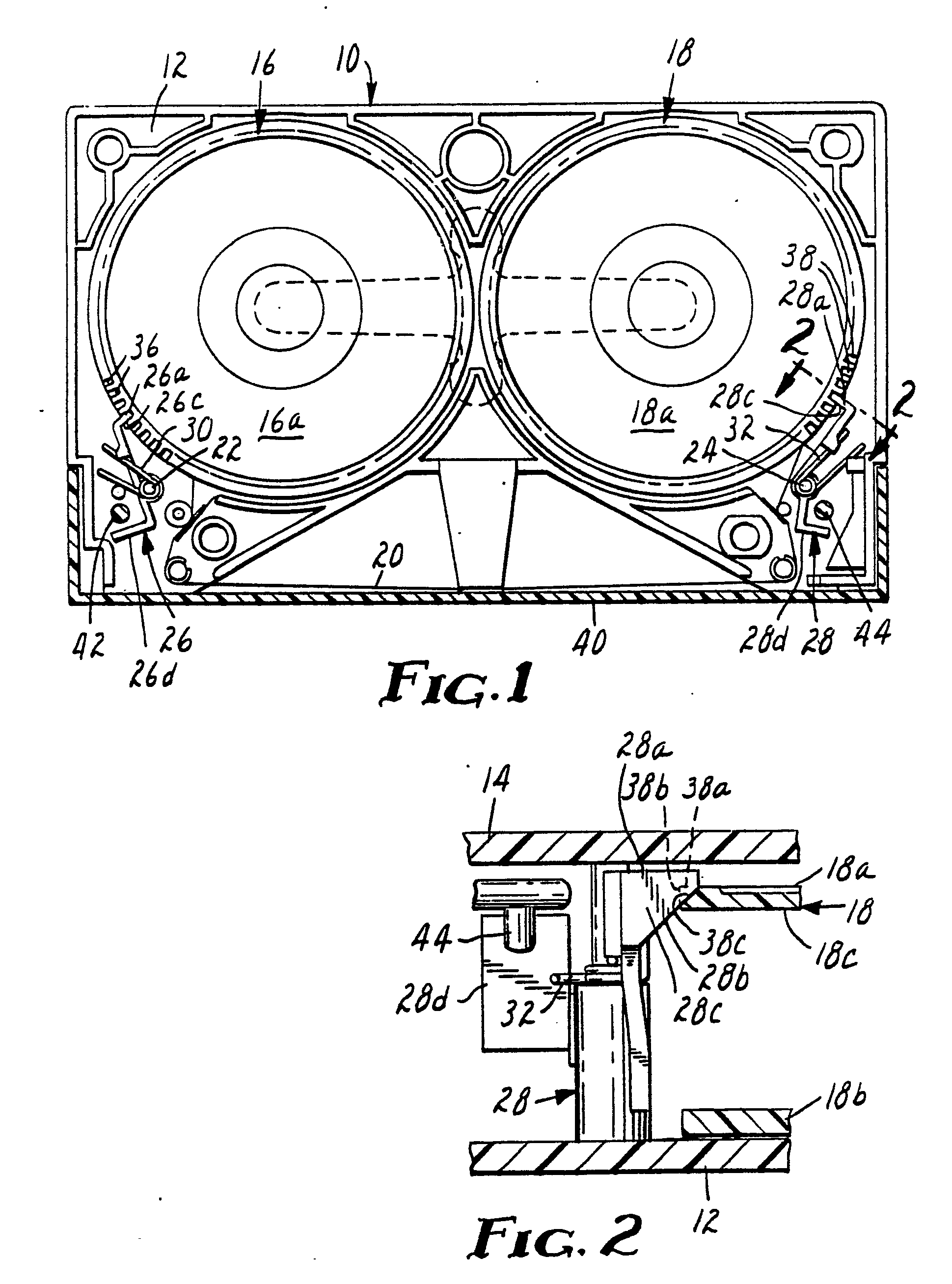
|
| (51) |
International Patent Classification (IPC)4: G11B 23/087 |
|
| (54) |
Braking mechanism for cassette tape reel
Bremsvorrichtung für die Bandspule einer Bandkassette
Mécanisme de freinage de la bobine d'une cassette de bande
|
| (84) |
Designated Contracting States: |
|
DE FR GB IT |
| (30) |
Priority: |
24.10.1983 US 544867
|
| (43) |
Date of publication of application: |
|
08.05.1985 Bulletin 1985/19 |
| (73) |
Proprietor: MINNESOTA MINING AND MANUFACTURING COMPANY |
|
St. Paul,
Minnesota 55133-3427 (US) |
|
| (72) |
Inventor: |
|
- Wulfing, James J.
c/o Minnesota Mining and
P.O. Box 33427
St. Paul
Minnesota 55133 (US)
|
| (74) |
Representative: Baillie, Iain Cameron et al |
|
Ladas & Parry,
Altheimer Eck 2
80331 München
80331 München (DE) |
| (56) |
References cited: :
EP-A- 0 094 205
GB-A- 2 015 477
|
FR-A- 2 350 659
|
|
| |
|
|
|
|
| |
|
| Note: Within nine months from the publication of the mention of the grant of the European
patent, any person may give notice to the European Patent Office of opposition to
the European patent
granted. Notice of opposition shall be filed in a written reasoned statement. It shall
not be deemed to
have been filed until the opposition fee has been paid. (Art. 99(1) European Patent
Convention).
|
Technical field
[0001] The invention concerns a braking mechanism for preventing rotation of a tape reel
of a recording tape cassette during handling and shipment.
Background art
[0002] Each of the Betamax and VHS videotape cassettes has a pair of plastic brake levers
which engage peripheral teeth in the lower flange of each tape reel to lock the reels
when the cassette is not in use. The braking mechanism of a conventional Betamax videotape
cassette is illustrated in Figs. 1-5 of U.S. Patent No. 4,214,719 (Kato). As disclosed
at the bottom of column 4, when the visor-type door or lid 5 is opened, actuating
projections 6' rotate or pivot brake levers 33a and 33b against urging forces of respective
torsion springs to disengage a finger 36 of each lever from the teeth 26 of the reels
(see also Fig. 11).
[0003] The braking mechanism of a conventional VHS videotape cassette is illustrated in
U.S. Patent No. 4,106,724 (Higashida). When a VHS videotape cassette is positioned
on a deck, a fixed pin 26 on the deck rotates or pivots a brake release member 21,
which in turn pivots the pair of brake levers 15 and 16 againstthe force of springs
19 and 20 to lift the fingers 15a and 16a out of engagement with the teeth 12 and
11, respectively.
[0004] The brake levers limit the amount of tape that can be wound into the Betamax and
VHS videotape cassettes and hence limit the playing time.
[0005] The takeup reel of the VHS-C (compact) videotape cassette has peripheral teeth in
its lower flange, by which the reel is locked when the cassette is not in use. The
outer face of the supply reel is formed with teeth which fit into indentations formed
in the base of the cassette and are pressed against those indentations by a metal
leaf spring which is mounted on the cover of the cassette and presses against the
hub of the supply reel. In spite of this, the supply roll sometimes rotates when handled
and shipped so that the tape becomes loose and tangled.
[0006] EP-A-0094205 having an earlier priority date than the present application but published
after the priority date of the present application and which designates AT, BE, CH,
DE, FR, IT, LI, LU, NL, SE discloses a tape cassette having parallel top and bottom
walls, a rotatable tape reel having a flange with peripheral teeth and a pivotal brake
lever comprising a spring biased finger for fitting between adjacent teeth to releasably
lock the reel against rotation. In this reference the pivotal axis of the finger is
arranged in a parallel plane to the plane of the top and bottom walls. The cassette
disclosed in the said European Patent Application has the disadvantage that the spring
finger may be jolted out of location between adjacent teeth if the cassette is dropped.
In a preferred embodiment of this invention this disadvantage is overcome.
Disclosure of invention
[0007] The braking mechanism of the present invention effectively locks the reels of a recording
tape cassette against rotation during handling and storage but unlike conventional
Betamax and VHS videotape cassettes, it does not limit the amount of tape that can
be wound into the videocassette. As in each of the Betamax and VHS cassettes, the
novel braking mechanism includes (a) a rotatable tape reel having a flange formed
with peripheral teeth for releasably locking the reel against rotation, (b) a pivotable
brake lever including a finger which fits between adjacent teeth, and (c) spring means
biasing the lever to engage the finger with the teeth.
[0008] The novel braking mechanism differs from those of conventional Betamax and VHS videotape
cassettes in that the teeth are formed only in the outer face of said toothed flange
and the finger is formed with a tooth-engaging ramp which is inclined at an angle
of 30-60° to the untoothed inner face of said flange when the finger fits between
adjacent teeth.
[0009] Preferably the ramp and the roots of the teeth are inclined at the same angle when
the finger fits between adjacent teeth. To insure against slippage, the sides of the
teeth may be substantially perpendicular to the inner face of the toothed flange,
as are the sides of the finger when. it fits between adjacent teeth. In a preferred
embodiment of the invention, each tooth is triangular in the radial direction, a first
edge of the tooth extending parallel to the inner face of the toothed flange and a
second edge extending perpendicular to said inner face. The periphery of the flange
may be rounded between the roots of the teeth and the inner face of the toothed flange.
[0010] . When the invention is embodied in a Betamax, VHS or VHS-C videotape cassette, each
of which comprises a base and cover providing broad parallel bottom and top walls,
respectively, there may be a post projecting from the bottom wall on which the brake
lever is rotatably journalled. A coil spring may fit over the post to bias the brake
lever into engagement with the teeth of the outer flange. Preferably the tape reel
is positioned with its toothed flange adjacent the top wall, and the maximum spacing
between the top wall and the top of the finger is less than the thickness of the toothed
flange. Hence, even when the cassette is dropped onto concrete, the toothed flange
cannot override the finger.
[0011] A Betamax or VHS cassette embodying the invention would normally have two tape reels
and brake levers, and for economy both brake levers would be molded plastic such as
acetal resin or acrylonitrile-butadiene-styrene (ABS) copolymer. As in conventional
Betamax and VHS videotape cassettes, the spring means for each brake lever may be
a metal coil spring which fits over the post on which the brake lever is journalled.
Preferred metal coil spring materials are stainless steels, high carbon spring steels,
and copper or nickel base alloys.
Brief description of the drawing
[0012] Figures. 1-5 of the drawing show a Betamax-type videotape cassette embodying the
reel braking mechanism of the invention wherein:
Fig. 1 is a schematic top view of a cassette with its cover removed;
Fig. 2 is an enlarged fragmentary cross-section along line 2-2 of Fig. 1 showing details
of one of the toothed flanges and its brake lever;
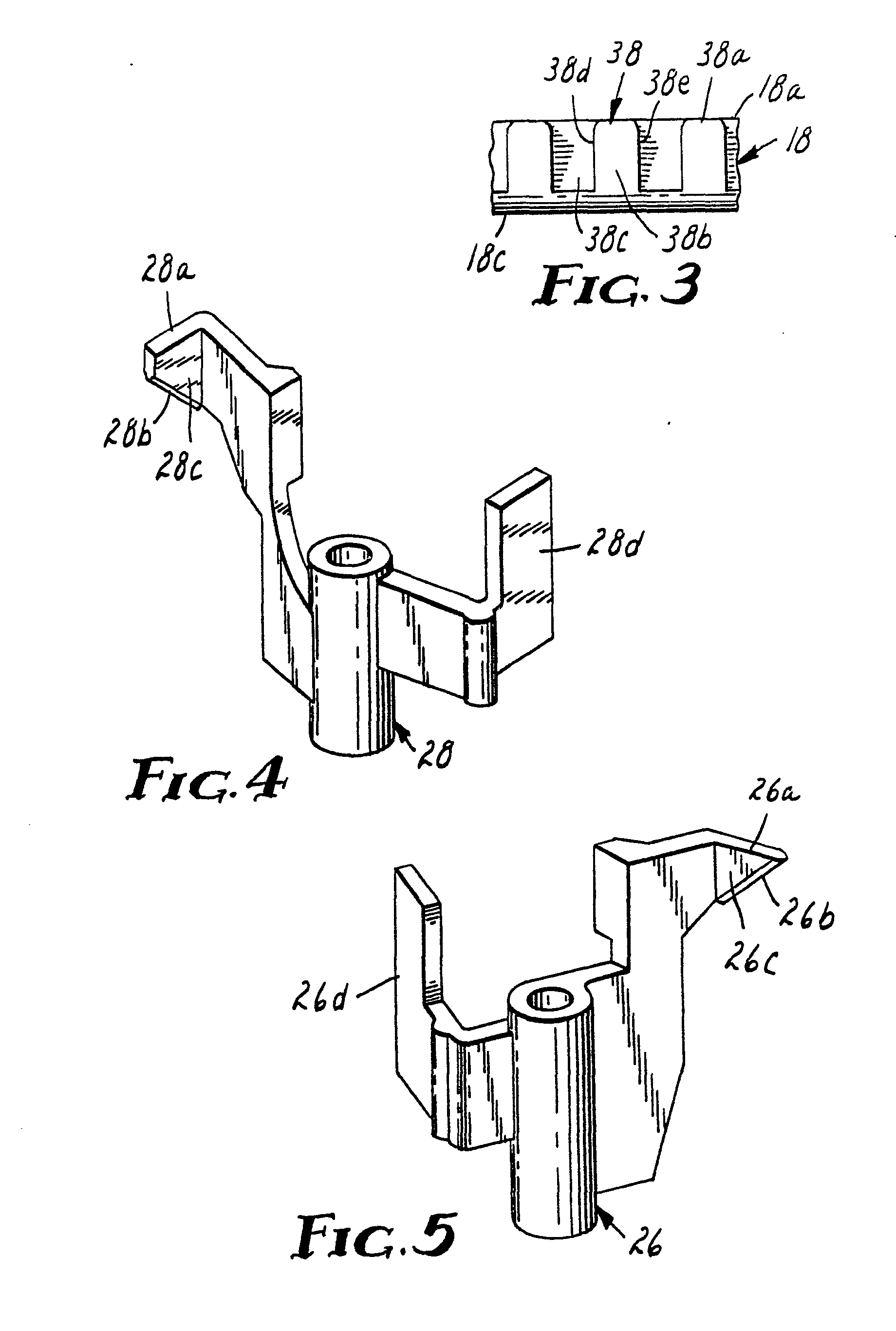
Fig. 3 is an enlarged partial edge view showing the shape of the teeth of flanges
of the cassette;
Fig. 4 is an enlarged perspective view of one of the brake levers; and
Fig. 5 is an enlarged perspective view of the other brake lever.
Detailed description
[0013] The Betamax-type videotape cassette 10 of Fig. 1 comprises a base 12, a cover 14,
two tape reels 16 and 18, and a length of tape 20 wound on and extending between the
reels. The reels 16 and 18 have toothed upper flanges 16a and 18a and untoothed lower
flanges, one of which 18b, is shown in Fig. 2. Projecting from the bottom wall of
the base 12 are two posts 22 and 24 on which are journalled brake levers 26 and 28,
respectively. When the cassette 10 is not in use, a wire coil spring 30 which fits
over the post 22 biases the brake lever 26 clockwise into engagement with teeth 36
at the periphery of one upper flange 16a. A second wire coil spring 32 biases the
brake lever 28 counterclockwise into engagement with teeth 38 of the other upper flange
18a.
[0014] The brake levers 26 and 28 have fingers 26a and 28a which are formed with tooth-engaging
ramps 26b and 28b, respectively, that are inclined at an angle of 45° to the inner
faces of the upper flanges 16a and 18a, respectively, when the fingers engage the
flanges. The roots of the teeth 36 and 38 of the upper flanges 16a and 18a, respectively,
are also inclined at an angle of 45° to the inner faces of the upper flanges 16a and
18a.
[0015] In the radial direction (as in Fig. 2) each of the teeth 36 and 38 is triangular.
A first edge 38a of each of the teeth 38 extends parallel to, a second edge 38b extends
perpendicular to, and the root edge 38c extends at an angle of 45° to the inner face
18c of the upper flange 18a. The periphery of the flange 18a is rounded between the
roots of the teeth 38 and the inner face 18c of the flange 18a.
[0016] In the circumferential direction (Fig. 3), the sides 38d and 38e of each of the teeth
38 are substantially perpendicular to the inner face 18c of the upper flange 18a.
The sides 26c and 28c of the fingers 26a and 28a likewise are substantially perpendicular
to the inner faces of the toothed flanges when the fingers engage the teeth 36 and
38.
[0017] When the cassette 10 is placed on a Betamax deck, the visor-type door 40 is pivoted
open, thus pivoting projections 42 and 44 which contact arms 26d and 28d of the brake
levers 26 and 28, respectively. This pivots the brake levers to lift their fingers
26a and 28a out of engagement with the teeth 36 and 38, thus freeing the tape reels
16 and 18 for rotation.
[0018] A Betamax-type videotape cassette as shown in Figure 1-4 has been constructed with
the brake levers molded from acetal plastic and the upper flanges 16a and 18a molded
from styreneacrylonitrile copolymer plastic. Each of the teeth 36 and 38 had the following
dimensions:
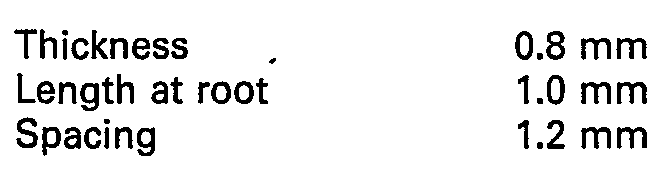
[0019] Each of the fingers 26a and 28a had a width of 1.1 mm. A length of magnetic recording
tape was wound into the cassette such that when fully wound onto either reel, the
outermost convolution was 7.4 cm in diameter, within 0.4 mm of the periphery of the
reel, and within an average of 0.8 mm of the walls around the reel peripheries. In
contrast, Betamax-type cassettes now on the market have a maximum wound tape diameter
of about 7.0 cm. Hence, the present invention allows the tape length to be increased
about 13 percent.
Claims for the following Contracting State(s) : s: DE, FR, IT
1. A recording tape cassette (10) including a base (12) and cover (14) providing broad
parallel bottom and top walls, respectively, a rotatable tape reel (16, 18) having
a flange (16A, 18A) formed with peripheral teeth (36, 38) for releasably locking the
reel (16, 18) against rotation, said teeth (36, 38) being formed only in the outer
face of said flange (16A, 18A), a pivotable brake lever (26, 28) including a finger
(26A, 28A) which fits between adjacent teeth (36, 38), said finger (26A, 28A) being
formed with a tooth-engaging ramp (26B, 28B) which is inclined at an angle of 30-600 to the untoothed inner face (18C) of said flange (16A, 18A) when the finger (26A,
28A) fits between adjacent teeth (36, 38), the roots of the teeth (36, 38) and the
ramp (26B, 28B) being inclined at the same angle when the finger (26A, 28A) fits between
adjacent teeth (36, 38), the sides of said teeth (36, 38) being substantially perpendicular
to the inner face (18C) of said flange (16A, 18A), as are the sides of the finger
(26A, 28A) when it fits between adjacent teeth (36, 38), and spring means (30, 32)
biasing the lever (26, 28) to engage the finger (26A, 28A) with the teeth (36, 38),
characterised in that said reel (16, 18) is positioned with its toothed flange (16A,
18A) adjacent the top wall (14), and the maximum spacing between the top wall (14)
and the top of said finger (26A, 28A) is less than the thickness of said toothed flange
(16A, 18A).
2. Cassette (10) as defined in claim 1 wherein a post (22, 24) projects from the bottom
wall (12) and said brake lever (26, 28) is pivotably journalled on said post.
3. Cassette (10) as defined in claim 2 wherein a coil spring (30, 32) fits over the
post (22, 24) and biases the finger (26A, 28A) of the brake lever (26, 28) toward
said teeth (36, 38).
4. Cassette (10) as defined in any preceding claim wherein each tooth (36, 38) is
substantially triangular in the radial direction and a first edge (38A) of the tooth
extends parallel to the inner face (18C) of said flange (16A, 18A).
- 5. Cassette (10) as defined in claim 4 wherein a second edge (38C) of the tooth
(36, 38) extends perpendicular to the inner face (18C) of said flange (16A, 18A).
Claims for the following Contracting State(s) : GB
1. A recording tape cassette (10) including (a) a rotatable tape reel (16, 18) having
a flange (16A, 18A) formed with peripheral teeth (36, 38) for releasably locking the
reel (16, 18) against rotation, (b) a pivotable brake lever (26, 28) including a finger
(26A, 28A) which fits between adjacent teeth (36, 38), and (c) spring means (30, 32)
biasing the lever (26, 28) to engage the finger (26A, 28A) with the teeth (36, 38),
characterised in that:
the teeth (36, 38) are formed only in the outer face of said flange (16A, 18A) and
the finger (26A, 28A) is formed with a tooth-engaging ramp (26B, 28B) which is inclined
at an angle of 30-600 to the untoothed inner face (18C) of said flange (16A, 18A) when the finger (26A,
28A) fits between adjacent teeth (36, 38).
2. Cassette (10) as defined in claim 1 wherein the roots of the teeth (36, 38) and
the ramp (26B, 28B) are inclined at the same angle when the finger (26A, 28A) fits
between adjacent teeth (36, 38).
3. Cassette (10) as defined in claim 2 wherein the sides of said teeth (36, 38) are
substantially perpendicular to the inner face (18C) of said flange (16A, 18A), as
are the sides of the finger (26A, 28A) when it fits between adjacent teeth (36, 38).
4. Cassette (10) as defined in claim 3 and further comprising a base (12) and cover
(14) providing broad parallel bottom and top walls, respectively, and a post (22,
24) projecting from the bottom wall (12) on which said brake lever (26, 28) is pivotably
journalled, wherein the improvement further comprises:
said reel (16, 18) is positioned with its toothed flange (16A, 18A) adjacent the top
wall (14), and the maximum spacing between the top wall (14) and the top of said finger
(26A, 28A) is less than the thickness of said toothed flange (16A, 18A).
5. Cassette (10) as defined in claim 4 wherein a coil spring (30, 32) fits over the
post (22, 24) and biases the finger (26A, 28A) of the brake lever (26, 28) toward
said teeth (36, 38).
6. Cassette (10) as defined in claim 3 wherein each tooth (36, 38) is substantially
triangular in the radial direction and a first edge (38A) of the tooth extends parallel
to the inner face (18C) of said flange (16A, 18A).
7. Cassette (10) as defined in claim 6 wherein a second edge (38C) of the tooth (36,
38) extends perpendicular to the inner face (18C) of said flange (16A, 18A).
Patentansprüche für folgende(n) Vertragsstaat(en) : DE, FR, IT
1. Aufzeichnungsbandkassette (10) mit einem Unterteil (12) und einem Deckel (14),
die eine breite Bodenwand und eine breite, zu der Bodenwand parallele Decke bilden,
mit einer drehbaren Bandspule (16, 18) mit einem Flansch (16A, 18A), der Umfangszähne
(36, 38) zum lösbaren Verriegeln der Spule (16, 18) gegen eine Drehung besitzt, wobei
diese Zähne (36, 38) nur in der Außenfläche des Flansches (16A, 18A) ausgebildet sind,
ferner mit einem schwenkbaren Bremshebel (26, 28), der einen Finger (26A, 28A) zum
passenden Einrücken zwischen einander benachbarte Zähne (36, 38) aufweist, wobei der
Finger (26A, 28A) mit einer Zahnanlagerampe (26B, 28B) ausgebildet ist, die bei zwischen
einander benachbarten Zähne (36, 38) eingerückten Finger (26A, 28A) unter einem Winkel
von 30 bis 60° zu der unverzahnten Innenfläche (18C) des Flansches (16A, 18A) geneigt
ist, bei zwischen einander benachbarten Zähnen (36, 38) eingerücktem Finger (26A,
28A) unter demselben Winkel geneigt sind, die Seitenflächen der Zähne (36, 38) und
die Seitenflächen des zwischen einander benachbarten Zähnen (36, 38) eingerückten
Fingers (26A, 28A) zu der Innenfläche (18C) des Flansches im wesentlichen rechtwinklig
sind, und mit Federmitteln (30, 32) die den Hebel (26, 28) zum Einrücken des Fingers
(26A, 28A) zwischen den Zähnen (36, 38) vorbelasten, dadurch gekennzeichnet, daß die
Spule (16, 18) so angeordnet ist, daß sich ihr gezahnter Flansch (16A, 18A) im Bereich
der Decke (14) befindet und der maximale Abstand zwischen der Decke (14) und der Oberseite
des Fingers (26A, 28A) kleiner ist als die Stärke des gezahnten Flansches (16A, 18A).
2. Kassette nach Anspruch 1, dadurch gekennzeichnet, daß von der Bodenwand (12) ein
Pfosten (22, 24) vorsteht, auf dem der Bremshebel (26, 28) schwenkbar gelagert ist,
die Spule (16, 18) so angeordnet ist, daß sich ihr gezahnter Flansch (16A, 18A) im
Bereich der Decke (14) befindet, und daß der maximale Abstand zwischen der Decke (14)
und der Uberseite des Fingers (26A, 28A) kleiner ist als die Stärke des gezahnten
Flansches (16A, 18A).
3. Kassette (10) nach Anspruch 2, dadurch gekennzeichnet, daß der Pfosten (22, 24)
von einer Schraubenfeder (30, 32) passend umgeben ist, die den Finger (26A, 28A) des
Bremshebels (26, 28) zu den Zähnen (36, 38) hin vorbelastet.
4. Kassette (10) nach einem der vorhergehenden Ansprüche, dadurch gekennzeichnet,
daß jeder Zahn (36, 38) in der radialen Richtung im wesentlichen dreieckig ist und
ein erster Rand (38A) des Zahns sich parallel zu der Innenfläche (18C) des Flansches
(16A, 18A) erstreckt.
5. Kassette (10) nach Anspruch 4, dadurch gekennzeichnet, daß ein zweiter Rand (38C)
des Zahnes (36, 38) sich rechtwinklig zu der Innenfläche (18C) des Flansches (16A,
18A) erstreckt.
Patentansprüche für folgende(n) Vertragsstaat(en) : GB
1. Aufzeichnungsbandkassette (10) mit (a) einer drehbaren Bandspule (16, 18) mit einem
Flansch (16A, 18A), der Umfangszähne (36,38) zum lösbaren Verriegeln der Spule (16,
18) gegen eine Drehung besitzt, (b) mit einem schwenkbaren Bremshebel (26, 28), der
einen Finger (26A, 28A) zum passenden Einrücken zwischen einander benachbarte Zähne
(36, 38) aufweist, und mit (c) Federmitteln (30, 32), die den Hebel (26, 28) zum Einrücken
des Fingers (26A, 28A) zwischen den Zähnen (36, 38) vorbelasten, dadurch gekennzeichnet,
daß
die Zähne (36, 38) nur in der Außenfläche des Flansches (16A, 18A) ausgebildet sind
und
der Finger (26A, 28A) mit einer Zahnanlagerampe (26B, 28B) ausgebildet ist, die bei
zwischen einander benachbarten Zähne (36, 38) eingerückten Finger (26A, 28A) unter
einem Winkel von 30 bis 60° zu der unverzahnten Innenfläche (18C) des Flansches (16A,
18A) geneigt ist.
2. Kassette (10) nach Anspruch 1, dadurch gekennzeichnet, daß bei zwischen einander
benachbarten Zähnen (36, 38) eingerücktem Finger (26A, 28A) die Füße der Zähne (36,
38) und die Rampe (26B, 28B) unter demselben Winkel geneigt sind.
3. Kassette (10) nach Anspruch 2, dadurch gekennzeichnet, daß die Seitenflächen der
Zähne (36, 38) und die Seitenflächen des zwischen einander benachbarten Zähnen (36,
38) eingerückten Fingers (26A, 28A) zu der Innenfläche (18C) des Flansches im wesentlichen
rechtwinklig sind.
4. Kassette (10) nach Anspruch 3 mit einem Unterteil (12) und einem Deckel (14), die
eine breite Bodenwand bzw. einen breiten, zu der Bodenwand parallelen Deckel bilden,
sowie mit einem von der Bodenwand (12) vorstehenden Pfosten, auf dem der Bremshebel
(26, 28) schwenkbar gelagert ist, dadurch gekennzeichnet, daß
die Spule (16,18) so angeordnet ist, daß sich ihr gezahnter Flansch (16A, 18A) im
Bereich der Decke (14) und der Oberseite des Fingers (26A, 28A) kleiner ist als die
Stärke des gezahnten Flansches (16A, 18A).
5. Kassette (10) nach Anspruch 4, dadurch gekennzeichnet, daß der Pfosten (22, 24)
von einer Schraubenfeder (30, 32) passend umgeben ist, die den Finger (26A, 28A) des
Bremshebels (26, 28) zu den Zähnen (36, 38) hin vorbelastet.
6. Kassette (10) nach Anspruch 3, dadurch gekennzeichnet, daß jeder Zahn (36, 38)
in der radialen Richtung im wesentlichen dreieckig ist und ein erster Rand (38A) des
Zahns sich parallel zu der Innenfläche (18C) des Flansches (16A, 18A) erstreckt.
7. Kassette (10) nach Anspruch 6, dadurch gekennzeichnet, daß ein zweiter Rand (38C)
des Zahnes (36, 38) sich rechtwinklig zu der Innenfläche (18C) des Flansches (16A,
18A) erstreckt.
Revendications pour l'(les) Etat(s) contractant(s) suivant(s) : DE, FR, IT
1. Cassette de bande d'enregistrement (10) comprenant une base (12) et un couvercle
(14) constituant de grandes parois inférieure et supérieure parallèles, respectivement,
une bobine de bande rotative (16, 18) comportant une joue (16a, 18a) dans laquelle
sont formées des dents périphériques (36, 38) pour bloquer de façon libérable la bobine
(16, 18) contre une rotation, lesdites dents (36, 38) étant formées seulement dans
la face extérieure de ladite joue (16a, 18a), un levier de frein pivotant (26, 28)
comportant un doigt (26a, 28a) qui se loge entre des dents adjacentes (36, 38), ledit
doigt (26a, 28a) comportant une rampe d'attaque de dent (26b, 28b) qui est inclinée
suivant un angle de 30 à 60° par rapport à la face intérieure non dentée (18c) de
ladite joue (16a, 18a) lorsque le doigt (26a, 28a) se loge entre des dents adjacentes
(36, 38), les racines des dents (36, 38) et la rampe (26b, 28b) étant inclinées suivant
le même angle lorsque le doigt (26a, 28a) se loge entre des dents adjacentes (36,
38), les côtés desdites dents (36, 38) étant sensiblement perpendiculaires à la face
intérieure (18c) de ladite joue (16a, 18a), de même que les côtés du doigt (26a, 28a)
lorsqu'il se loge entre des dents adjacentes (36, 38), et des moyens élastiques (30,
32) qui rappellent le levier (26, 28) pour amener le doigt (26a, 28a) en prise avec
les dents (36, 38), caractérisée en ce que ladite bobine (16, 18) est disposée de
sorte que sa joue dentée (16a, 18a) est adjacente à la paroi supérieure (14), et l'espacement
maximal entre la paroi supérieure (14) et le dessus dudit doigt (26a, 28a) est inférieur
à l'épaisseur de ladite joue dentée (16a, 18a).
2. Cassette (10) suivant la revendication 1, dans laquelle un bossage (22, 24) fait
saillie à partir de la paroi inférieure (12) et ledit levier de frein (26, 28) est
supporté de façon pivotante sur ledit bossage.
3. Cassette (10) suivant la revendication 2, dans laquelle un ressort hélicoïdal (30,
32) est monté sur le bossage (22, 24) et rappelle le doigt (26a, 28a) du levier de
frein (26, 28) vers lesdites dents (36, 38).
4. Cassette (10) suivant l'une quelconque des revendications précédentes, dans laquelle
chaque dent (36, 38) est sensiblement triangulaire dans la direction radiale et un
premier bord (38a) de la dent est parallèle à la face intérieure (18c) de ladite joue
(16a, 18a).
5. Cassette (10) suivant la revendication 4, dans laquelle un deuxième bord (38c)
de la dent (36, 38) est perpendiculaire à la face intérieure (18c) de ladite joue
(16a, 18a).
Revendications pour l'(les) Etat(s) contractant(s) suivant(s) : GB
1. Cassette de bande d'enregistrement (10) comprenant (a) une bobine de bande rotative
(16, 18) comportant une joue (16a, 18a) dans laquelle sont formées des dents périphériques
(36, 38) pour bloquer de façon libérable la bobine (16,18) contre une rotation, (b)
un levier de frein pivotant (26,28) comportant un doigt (26a, 28a) qui se loge entre
des dents adjacentes (36, 38), et (c) des moyens élastiques (30,32) qui rappellent
le levier (26, 28) pour amener le doigt (26a, 28a) en prise avec les dents (36,38),
caractérisée en ce que: les dents (36, 38) sont formées seulement dans la face extérieure
de ladite joue (16a, 18a) et le doigt (26a, 28a) comporte une rampe d'attaque de dent
(26b, 28b) qui est inclinée suivant un angle de 30 à 60° par rapport à la face intérieure
non dentée (18c) de ladite joue (16a, 18a) lorsque le doigt (26a, 28a) se loge entre
des dents adjacentes (36, 38).
2. Cassette (10) selon la revendication 1, caractérisée en ce que les racines des
dents (36, 38) et la rampe (26b, 28b) sont inclinées suivant le même angle lorsque
le doigt (26a, 28a) se loge entre des dents adjacentes (36, 38).
3. Cassette (10) selon la revendication 2, caractérisée en ce que les côtés desdites
dents (36, 38) sont sensiblement perpendiculaires à la face intérieure (18c) de ladite
joue (16a, 18a), de même que les côtés du doigt (26a, 28a) lorsqu'il se loge entre
des dents adjacentes (36, 38).
4. Cassette (10) selon la revendication 3, comprenant en outre une base (12) et un
couvercle (14) constituant de grandes parois inférieure et supérieure parallèles,
respectivement, et un bossage (22, 24) faisant saillie à partir de la paroi inférieure
(12) sur lequel ledit levier de frein (26, 28) est supporté de façon pivotante, caractérisée
en ce que ladite bobine (16, 18) est disposée de sorte que sa joue dentée (16a, 18a)
est adjacente à la paroi supérieure (14), et l'espacement maximal entre la paroi supérieure
(14) et le dessus dudit doigt (26a, 28a) est inférieur à l'épaisseur de ladite joue
dentée (16a, 18a).
5. Cassette (10) selon la revendication 4, dans laquelle un ressort hélicoïdal (30,
32) est monté sur le bossage (22, 24) et rappelle le doigt (26a, 28a) du levier de
frein (26, 28) vers lesdites dents (36, 38).
6. Cassette (10) selon la revendication 3, dans laquelle chaque dent (36, 38) est
sensiblement triangulaire dans la direction radiale et un premier bord (38a) de la
dent est parallèle à la face intérieure (18c) de ladite joue (16a, 18a).
7. Cassette (10) selon la revendication 6, dans laquelle un deuxième bord (38c) de
la dent (36, 38) est perpendiculaire à la face intérieure (18c) de ladite joue (16a,
18a).