| (19) |
 |
|
(11) |
EP 0 165 674 B1 |
| (12) |
EUROPEAN PATENT SPECIFICATION |
| (45) |
Mention of the grant of the patent: |
|
01.06.1988 Bulletin 1988/22 |
| (22) |
Date of filing: 23.04.1985 |
|
| (51) |
International Patent Classification (IPC)4: F16B 13/04 |
|
| (54) |
Insert for a drywall
Einsatzbuchse für poröse Wände
Insert pour mur friable
|
| (84) |
Designated Contracting States: |
|
AT BE CH DE FR GB IT LI LU NL SE |
| (30) |
Priority: |
11.05.1984 US 609260
|
| (43) |
Date of publication of application: |
|
27.12.1985 Bulletin 1985/52 |
| (73) |
Proprietor: ILLINOIS TOOL WORKS INC. |
|
Chicago,
Illinois 60631-2887 (US) |
|
| (72) |
Inventors: |
|
- Ernst, Richard J.
Palatine
Illinois 60067 (US)
- Peterson, Francis C.
Woodbury
Connecticut 06798 (US)
- Sledz, Melissa L.
Streamwood
Illinois 60103 (US)
|
| (74) |
Representative: Rackham, Stephen Neil et al |
|
GILL JENNINGS & EVERY,
Broadgate House,
7 Eldon Street
London EC2M 7LH
London EC2M 7LH (GB) |
| (56) |
References cited: :
EP-A- 0 064 166
DE-A- 3 122 503
US-A- 3 832 931
|
AT-B- 239 505
US-A- 3 516 324
US-A- 4 430 033
|
|
| |
|
|
|
|
| |
|
| Note: Within nine months from the publication of the mention of the grant of the European
patent, any person may give notice to the European Patent Office of opposition to
the European patent
granted. Notice of opposition shall be filed in a written reasoned statement. It shall
not be deemed to
have been filed until the opposition fee has been paid. (Art. 99(1) European Patent
Convention).
|
[0001] The present invention relates to an insert, and particularly to an insert for use
in drywall or sheetrock construction. Because drywall is a friable gypsum based material,
fastening articles to it is difficult. Generally, two different methods are used.
For light weight articles, plastic expansion anchors are commonly used. Such anchors
require three steps to install them. First, a hole is drilled into the drywall. Then,
the insert is pushed into the hole. Finally, a threaded fastener is advanced into
the anchor spreading the anchor into engagement with the drywall. Typically such anchors
include a generally hollow cyclindrical body with a flanged end. One such anchor which
does not include a flanged end is shown in AT-B-239505. This anchor includes a projection
of helical form which when the threaded fastener is screwed into it is spread into
engagement with sides of a pre-drilled clearance hole.
[0002] For heavy duty applications, toggle bolts are generally used to attach articles to
a drywall. While toggle bolts are generally effective, they are also generally expensive
because they involve a plurality of parts which must move relative to one another.
Another disadvantage of toggle bolts is that they sometimes present difficult installation
problems, particularly in the sequence of assembly.
[0003] According to this invention the body of such an anchor has an exterior thread and
a drilling end, the drilling end including means for allowing passage of an elongated
fastener through the body and beyond the drilling end.
[0004] The present invention avoids a separate drilling operation and provides an anchor
which is simple to install and inexpensive to manufacture. It also has improved pullout
reistance compared to light duty plastic anchors, and is significantly cheaper and
easier to install than toggle type anchors.
[0005] Preferably the drilling end has a maximum lateral dimension substantially equal to
the root diameter of the threaded portion, and the crest diameter of the threaded
portion is preferably substantially twice that of the root diameter. These two features
are important to achieve a proper threaded connection in the drywall. Because drywall
is made of a weak friable material, a high thread is needed to transfer pullout forces
to as much of the material as possible. By making the width of the drilling portion
equal to the root diameter of the threaded portion, the drilling operation removes
only as much material as is necessary, leaving behind a maximum amount of workpiece
material for thread engagement.
[0006] The threaded and drilling portions are preferably generally equal in length to each
other, and are generally equal in length to the thickness of standard drywall material.
This configuration allows the drilling operation to be completed prior to the start
of thread formation in the drywall. Since axial advancement of the insert is significantly
slower in the drilling operation than in the thread forming operation, it is necessary
that these operations not be performed simultaneously. However, a distinct advantage
of the insert of the present invention is that these two operations can be performed
in a single step or motion without the need to pre-drill a hole in the drywall with
a separate tool.
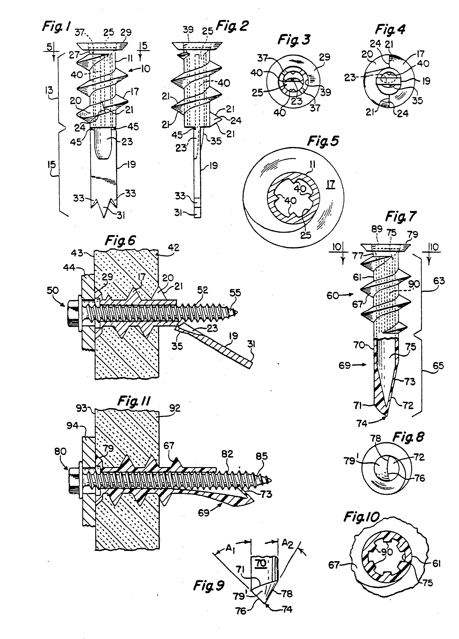
[0007] Two embodiments of anchors in accordance with this invention will now be described
with reference to the accompanying drawings, in which:-
Figure 1 is a side elevation of a first embodiment;
Figure 2 is a front elevation taken from the right side as shown in Figure 1;
Figure 3 is a plan view;
Figure 4 is an under plan view;
Figure 5 is a sectional elevation taken along the line 5-5 shown in Figure 1;
Figure 6 is a partially sectioned side elevation showing the first embodiment installed
in a workpiece;
Figure 7 is a side elevation of a second embodiment;
Figure 8 is an underplan of the second embodiment;
Figure 9 is a rear elevation of the tip of the second embodiment taken from the from
the left side of Figure 7;
Figure 10 is a sectional elevation taken along the line 10-10 shown in Figure 7; and,
Figure 11 is a partially sectioned side elevation showing the second embodiment installed
in a workpiece.
[0008] Referring now to the drawings, wherein like parts are designated by the same numerals
throughout the various Figures, Figures 1 to 6 illustrate a first embodiment which
is moulded from zinc. The insert 10 is comprised of a cyclindrical body 11 on which
is disposed a high thread 17. A flange 29 is disposed at one end of the body and a
flat drilling portion or blade 19 is disposed at the other end thereof. An axial bore
25 extends through the cylindrical body 11 and communicates with a spoon-like opening
23 in the blade 19. The thread 17 is separated from the flange 29 by the space 27.
The axial length 13 of the threaded portion of the cylindrical body is generally the
same as the axial length 15 of the drilling portion 19. The thread 17 includes notches
20. The notches form a generally radial surface 24 bounded by cutting edges 21. At
the juncture of the threaded portion and the drilling portion, weakening slots 45
facilitate the lateral deflection of the blade 19 when a threaded fastener is driven
through the threaded insert. The spoon-like opening 23 forms a curved wall 35 which
guides the tip of a fastener driven through the insert.
[0009] The drilling operation used to install the threaded insert is intended to be achieved
with a hand-powered Phillips screwdriver. Figure 3 shows the Phillips recess formed
in the upper end of the first embodiment. Four slots 37 are formed in the bottom of
the recess 39 in the upper end of the insert. The hole forming configuration of the
first embodiment is shown in Figures 1, 2 and 4. A central spike 31 is formed at the
extreme end of the blade 19 and the spike 31 extends beyond the peripheral spikes
33. The spike 31 tends to maintain the location of the insert during drilling, while
the spikes 33 tend to neatly cut the paper covering which is used on the surface of
drywall. After the paper is cut, the spikes 31 and 33 continue to form a bore in the
drywall as the anchor is rotated. After the drilling operation is completed, the thread
17 begins to form a mating thread in the drywall material. The cutting edges 21 assist
in the formation of the threads in the drywall.
[0010] Figures 3 and 5 show the splines 40 on the interior of the bore 25. Depending on
the hardness of the material comprising the insert and the crest diameter of an associated
threaded fastener, the height and shape of the splines can be varied.
[0011] Figure 6 shows the threaded insert as it appears when fully installed. The threads
17 of the insert are engaging the drywall 42. The upper surface of the flange 29 is
flush with the outer surface 43 of the drywall 42. This flush condition is obtained
by the use of a low profile head 29 and by the presence of the space 27. The discontinuation
of the thread 17 before reaching the head 29 creates a space in the thread form in
the drywall material which allows compression of adjacent material by the flange 29,
and which, therefore, allows the uppermost surface of the flange 29 to be flush with
the outer surface 43 of the drywall.
[0012] In Figure 6 it can also be seen that the insertion of the threaded fastener 50 through
the insert causes the blade 19 to deflect laterally. The deflecting feature of the
drilling portion is beneficial in that it allows the use of a screw which has a predetermined
length regardless of the thickness of the material 44 being fastened.
[0013] Another feature of the present invention is that the break-off nature of the blade
19 can be used in an alternative way. Occasionally, drywall is placed over much harder
surfaces such as concrete or cement block. In such applications; it is often the case
that a small amount of space, generally less than 3/4", lies between the back of the
drywall and the surface of the supporting structure. When this is encountered, the
insert of the present invention can be used in the following manner.
[0014] A hand powered screwdriver together with the insert 10 are used to form a hole in
the drywall. Once the hole is formed the insert is removed. The blade 19 can then
be manually broken off at the location of the weakening slots 45. The insert can then
be threaded into the drywall 42, without any danger of the blade 19 contacting the
supporting structure.
[0015] Figures 7 through 11 show a second embodiment of the present invention. The second
embodiment is a plastics moulded threaded insert 60 comprised of a generally cylindrical
body 61 and an external thread 67 disposed thereon. An elongated drilling tip 69 is
formed at one end of the body and a low profile flange 79 at the other end. The thread
67 stops before reaching the flange 79 forming an unthreaded neck 77. The length 63
of the threaded portion is generally equal to the length 65 of the drilling tip 69.
A bore 75 extends from the flanged end of the insert into the drilling tip 69. As
in the first embodiment, the flanged end 79 includes a recess 89 and slots to receive
a Phillips driver. The drilling tip 69 is comprised of a conical point 74 and a flat
surface 72. A web 73 closes off the bore 75, and prevents dust from entering the bore
during the drilling operation.
[0016] Figure 8 shows the drilling end of the insert 60. The conical point 74 is comprised
of a generally conical surface 79' and flat surface 72. The cutting edge 76 forms
a first angle A1 with the axial portion of the drill tip 69, and the trailing edge
78 forms a second angle A2 with the axial portion of the drill tip 69. Angle A1 is
greater than angle A2 in order to ensure that the cutting edge 76 contacts the drywall
during the drilling operation. The generally conical surface 79' slopes in the direction
of the flanged end from the cutting edge 76 to the trailing edge 78. The sloping surface
79' is not purely conical, but forms a generally helical edge 71 at the intersection
of the surface 79' and the axially oriented surface 70.
[0017] Figure 10 is a sectional view showing splines 90 on the interior of the cylindrical
body 61. Since the second embodiment is moulded plastic material, the splines 90 may
be thicker and more numerous than the splines 40 of the first embodiment, because
most plastic materials are softer and more easily tapped than a moulded zinc material.
[0018] Figure 11 is a sectional view showing the insert in its installed position in a drywall
workpiece 92. As in the first embodiment, the drill tip 69 allows axial penetration
of the fastener 80. The threads 82 disposed on the shank 85 engage the splines 90.
Because the article 94 is thin, the tip of the fastener 80 penetrates the wall 73
causing lateral deflection of the tip 69. However, a thicker article could be fastened
with the same screw, in which case the screw may not penetrate the wall 73. The threads
67 engage the drywall material 92, and the flange 79 is flush with the outer surface
93 of the workpiece 92.
1. An anchor (10) for use in friable material including a generally hollow cylindrical
body (13) with a flanged end (29), characterised in that the body (13) has an exterior
screw thread (17) and a drilling end (15), the drilling end (15) including means (23,
45, 73) for allowing passage of an elongated fastener (50, 80) through the body (13)
and beyond the drilling end (15).
2. An anchor according to claim 1, wherein the flanged end (29) includes a Phillips-type
drive recess (37) axially spaced inwardly of the flanged end (29).
3. An anchor according to claim 1 or 2, wherein the thread (17) is spaced from the
flanged end (29) by an amount less than one pitch of the thread (29).
4. An anchor according to any one of the preceding claims, wherein the drilling end
(15) has an axial length generally equal to that of the body (13), whereby drilling
of the material (42) by the drilling end (15) is substantially completed prior to
engagement of the thread (17) with it.
5. An anchor according to any one of the preceding claims, wherein the thread (17)
includes at least one interruption (20) having a generally radially flat surface (21)
for performing a thread cutting operation.
6. An anchor according to any one of the preceding claims, wherein the threaded portion
of the body (13) has a root and crest diameter such that the crest diameter is generally
twice that of the root diameter.
7. An anchor according to any one of the preceding claims, wherein the drilling end
(15) is generally flat and pointed (19) and includes spoon-like means (23) for engagement
with the fastener (50) and a weakened zone (45) for allowing the drilling end (15)
to deflect upon engagement of the fastener (50) with the means (23) and subsequent
advancement of the fastener (50) through the body (13).
8. An anchor according to any one of the preceding claims, wherein the drilling end
(15) is generally flat with an opening (23) at one end communicating with the means
(43,73) for allowing passage of an elongated fastener, the drilling end (15) having
a maximum lateral dimension generally equal to the root diameter of the exterior screw
thread and having a free end including three spikes (31, 33), one of the spikes (31)
being centrally located with respect to the axis of the body, the others (33) of the
spikes having points spaced at a distance generally equal to the root diameter, the
centrally located spike (31) extending further from the body than the others (33).
9. An anchor according to any one of claims 1 to 6, wherein the drilling end (65)
includes a generally conical point (74) having a flattened side (72) formed by a frangible
wall (73) substantially closing the hollow inside of the body (60) at the drilling
end (65), the wall (73) being penetrable by the elongate fastener (80) to permit the
passage beyond the drilling end (65).
10. An anchor according to claim 9, wherein the drilling end (69) includes a generally
cylindrical portion (70) adjacent the threaded portion (63), the conical point (74)
being deflectable to a non- axial position upon insertion of the fastener (80) through
the anchor (60), and including a curved surface (79) generally opposite to the flattened
side (72), the curved surface (79') being bounded by a first cutting edge (76) and
a second trailing edge (78), and a thick curved helical edge (71) defined by an intersection
between the curved surface (79') and said cylindrical portion (70) of the end (69).
1. Dübel (10) zum Einsatz in bröckeligem Werkstoff mit einem allgemein hohlen zylindrischen
Körper (13) mit einem angeflanschten Ende (29), dadurch gekennzeichnet, daß der Körper
(13) ein Außengewinde (17) und ein Bohrende (15) aufweist, wobei das Bohrende (15)
Mittel (23, 45, 73) aufweist, um einen Durchgang eines langgestreckten Befestigers
(50, 80) durch den Körper (13) hindurch und über das Bohrende (15) hinaus zu ermöglichen.
2. Dübel nach Anspruch 1, dadurch gekennzeichnet, daß das angeflanschte Ende (29)
eine Drehausnehmung (37) vom Typ Phillips aufweist, die axial innerhalb des angeflanschten
Endes (29) angeordnet ist.
3. Dübel nach Anspruch 1 oder 2, dadurch gekennzeichnet, daß das Gewinde (17) um eine
Länge, die weniger als eine Ganghöhe beträgt, von dem angeflanschten Ende (29) entfernt
angeordnet ist.
4. Dübel nach einem der vorangegangenen Ansprüche, dadurch gekennzeichnet, daß das
Bohrende (15) eine axiale Länge aufweist, die allgemein gleich der des Körpers (13)
ist, wodurch das Bohren des Werkstoffs (42) durch das Bohrende (15) im wesentlichen
beendet ist, bevor das Gewinde (17) mit ihm in Eingriff kommt.
5. Dübel nach einem der vorgangegangenen Ansprüche, dadurch gekennzeichnet, daß das
Gweinde (17) mindestens eine Unterbrechung (20) aufweist mit einer allgemein radial
ebenen Fläche (21), um einen Gewindeschneidvorgang auszuführen.
6. Dübel nach einem der vorangegangenen Ansprüche, dadurch gekennzeichnet, daß der
Gewindeteil des Körpers (13) einen Fußdurchmesser und einen Scheiteldurchmesser aufweist,
wobei der Scheiteldurchmesser allgemein doppelt so groß wie der Fußdurchmesser ist.
7. Dübel nach einem der vorangegangenen Ansprüche, dadurch gekennzeichnet, daß das
Bohrende (15) allgemein flach und zugespitzt (19) ist und ein löffelähnliches Mittel
(23) zum Eingriff mit dem Befestiger (50) und einen geschwächten Bereich (45) aufweist,
um dem Bohrende (15) nach dem Eingriff des Befestigers (50) mit dem Mittel (23) und
dem folgenden Durchgang des Befestigers (50) durch den Körper (13) ein Abbiegen zu
ermöglichen.
8. Dübel nach einem der vorangegangenen Ansprüche, dudurch gekennzeichnet, daß das
Bohrende (15) allgemein flach mit einer Öffnung (23) an einem Ende ausgebildet ist,
die mit den Mitteln (43, 73) zusammenwirkt, um den Durchgang eines langgestreckten
Befestigers zu ermöglichen, wobei das Bohrende (15) eine größte Längsabmessung aufweist,
die allgemein gleich dem Fußdurchmesser des Außengewindes ist und ein freies Ende
mit drei Zacken (31, 33) aufweist, wobei einer der Zacken (31) mittig mit Bezug auf
die Achse des Körpers angeordnet ist und die anderen Zacken (33) Spitzen aufweisen,
die in einer Entfernung angeordnet sind, die allgemein gleich dem Fußdurchmesser ist,
wobei die mittig angeordnete Zacke (31) sich weiter vom Körper weg erstreckt als die
anderen (33).
9. Dübel nach Anspruch 1 bis 6, dadurch gekennzeichnet, daß das Bohrende (65) eine
allgemein konische Spitze (74) aufweist mit einer abgeflachten Seite (72), die durch
eine abbrechbare Wand (73) gebildet wird, die im wesentlichen das hohle Innere des
Körpers (60) am Bohrende (65) verschließt; wobei die Wand (73) von dem langgestreckten
Befestiger (80) durchdringbar ist, um den Durchgang über das Bohrende (65) hinaus
zu ermöglichen.
10. Dübel nach Anspruch 9, dadurch gekennzeichnet, daß das Bohrende (69) einen allgemein
zylindrischen Teil (70) nahe dem Gewindeteil (63) aufweist, wobei die konische Spitze
(70) beim Einbringen des Besfestigers (80) durch den Dübel (60) in eine nicht-axiale
Stellung abbiegbar ist und eine gekrümmte Fläche (79') aufweist, die allgemein der
abgeflachten Seite (72) gegenüberliegt, wobei die gekrümmte Fläche (79') umgrenzt
wird durch eine erste Schneidkante (76), eine zweite Hinterkante (78) und eine stark
gekrümmte Schraubenkante (71), die durch einen Schnitt zwischen der gekrümmten Fläche
(79') und dem zylindrischen Teil (70) des Endes (69) gebildet wird.
1. Organe d'ancrage (10) à utiliser dans un matériau friable, comprenant un corps
globalement en creux et cytindrique (13) ayant une extrémité (29) à collerette, caractérisé
en ce que le corps (13) comporte un filet de vis extérieur (13) et une extrémité de
perçage (15), l'extrémité de perçage (15) comprenant des moyens (23,45,73) pour permettre
le passage d'un organe de fixation allongé (50, 80) à travers le corps (13) et au-delà
de l'extrémité de perçage (15).
2. Organe d'ancrage selon la revendication 1, dans lequel l'extrémité (29) à collerette
présente une empreinte (37) d'entraînement du type Phillips espacée axialement vers
l'intérieur de l'extrémité à collerette (29).
3. Organe d'ancrage selon la revendication 1 ou 2, dans lequel le filet (17) est espacé
de l'extrémité à collerette (29) d'une distance inférieure à un pas du filet (29).
4. Organe d'ancrage selon l'une quelconque des revendications précédentes, dans lequel
l'extrémité de perçage (15) présente une longueur axiale globalement égale à celle
du corps (13), de manière que le perçage du matériau (42) par l'extrémité de perçage
(15) soit sensiblement achevé avant l'entrée en prise du filet (17) avec lui.
5. Organe d'ancrage selon l'une quelconque des revendications précédentes, dans lequel
le filet (17) présente au moins une interruption (20) ayant une surface à peu près
radialement plate (21) pour exécuter une opération de coupe de filet
6. Organe d'ancrage selon l'une quelconque des revendications précédentes dans lequel
la partie filetée du corps (13) présente un diamètre de pied et un diamètre de crête
tel que le diamètre de crête est globalement double du diamètre de pied.
7. Organe d'ancrage selon l'une quelconque des revendications précédentes, dans lequel
l'extrémité de perçage (15) est globalement plate et pointue (19) et comprend des
moyens (23) analogues à une cuillère destinés à entrer en prise avec l'organe de fixation
(50) et une zone affaiblie (45) pour permettre à l'extrémité de perçage (15) de dévier
sous l'effet de l'entrée en prise de l'organe de fixation (50) avec les moyens (23),
et, ensuite, de la progression de l'organe de fixation (50) à travers de corps (13).
8. Organe d'ancrage selon l'une quelconque des revendications précédentes, dans lequel
l'extrémité de perçage (15) est globalement plate, avec une ouverture (23) à une extrémité
communiquant avec les moyens (43, 73) pour permettre le passage d'un organe de fixation
allongé, l'extrémité de perçage (15) ayant une dimension latérale maximale globalement
égale au diamètre de pied du filet de vis extérieur et ayant une extrémité libre comportant
trois dents (31, 33), l'une des dents (31) étant située centralement par rapport à
l'axe du corps, les autres dents (33) ayant des pointes espacées à une distance globalement
égale au diamètre de pied, la dent (31) située, centralement s'étendant davantage
à partir du corps que les autres dents (33).
9. Organe d'ancrage selon l'une quelconque des revendications 1 à 6, dans lequel l'extrémité
de perçage (65) comprend une pointe globalement conique (74) ayant un côté aplati
(72) formé par une paroi fragile (73) fermant sensiblement l'intérieur évidé du corps
(60) à l'extrémité de perçage (65), la paroi (73) pouvant être traversée par l'organe
de fixation allongé (80) pour qu'il puisse passer au-delà de l'extrémité de perçage
'(65).
10. Organe d'ancrage selon la revendication 9, dans lequel l'extrémité de perçange
(69) comprend une partie globalement cyclindrique (70) adjacente à la partie filetée
(63), la pointe conique (74) pouvant être déviée vers une position non axiale à la
suite de l'introduction de l'organe de fixation (80) à travers l'organe d'ancrage
(60), et présentant une surface arrondie (79) globalement opposée au côté aplati (72),
la surface arrondie (79') étant délimitée par une premièrè arête de coupe (76) et
par une second arête arrière (78), et un bord hélicoïdal incurvé et épais (71) défini
par une intersection entre la surface arrondie (79') et ladite partie cylindrique
(70) de l'extrémité (69).