| (19) |
 |
|
(11) |
EP 0 166 290 B1 |
| (12) |
EUROPEAN PATENT SPECIFICATION |
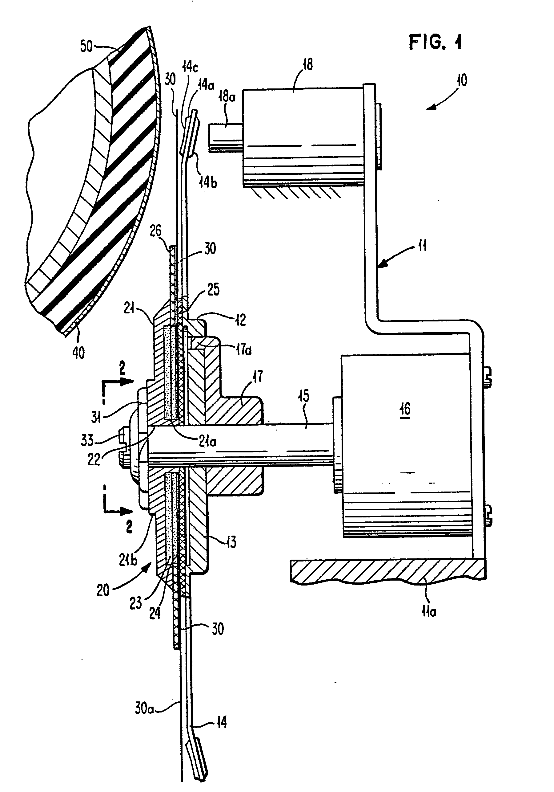
| (45) |
Mention of the grant of the patent: |
|
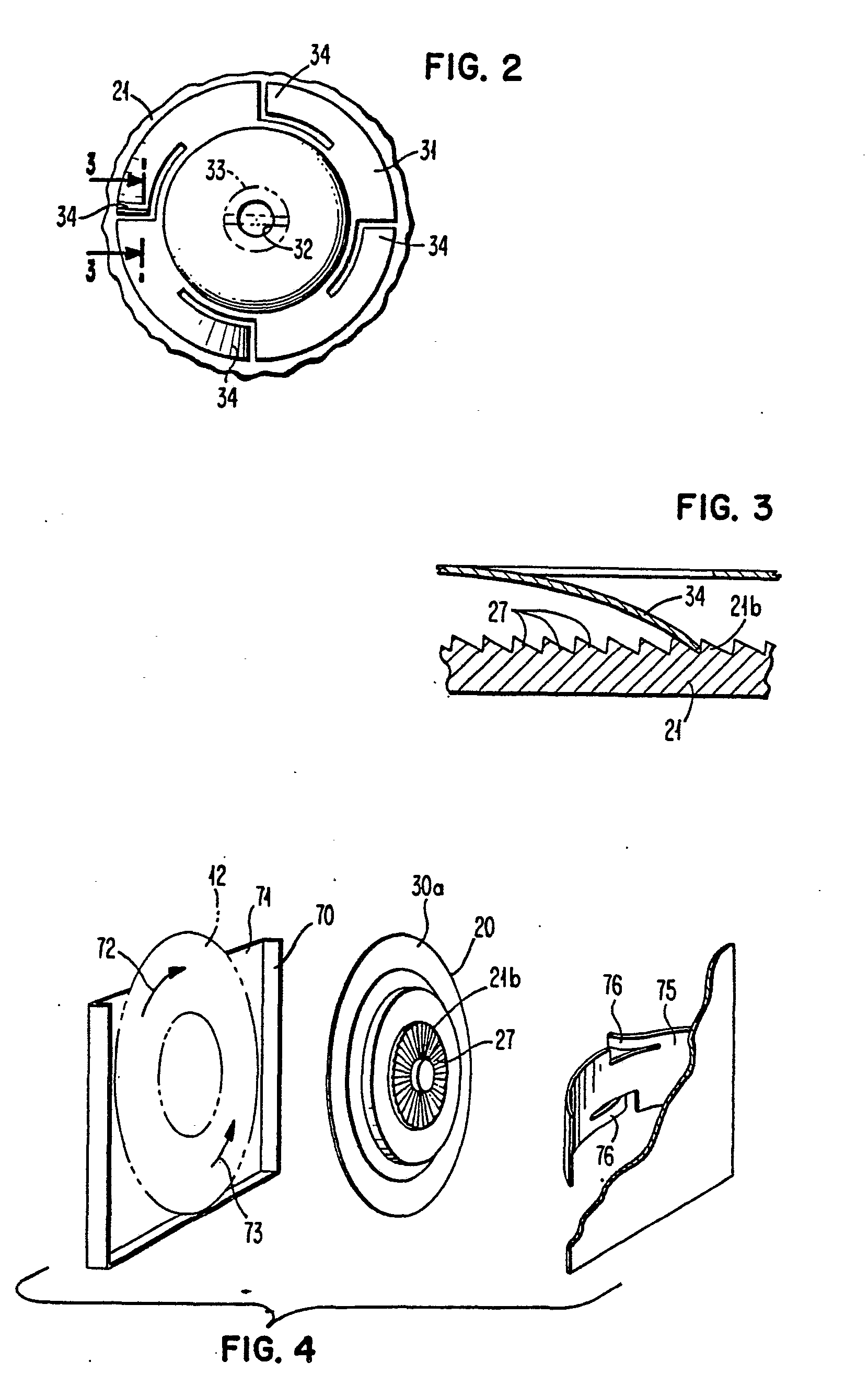
14.12.1988 Bulletin 1988/50 |
| (22) |
Date of filing: 11.06.1985 |
|
| (51) |
International Patent Classification (IPC)4: B41J 1/30 |
|
| (54) |
Drive mechanism for a ribbon disc
Antriebsmechanismus für eine Farbbandscheibe
Mécanisme d'entraînement pour un disque à ruban
|
| (84) |
Designated Contracting States: |
|
CH DE FR GB IT LI |
| (30) |
Priority: |
29.06.1984 US 626078
|
| (43) |
Date of publication of application: |
|
02.01.1986 Bulletin 1986/01 |
| (73) |
Proprietor: International Business Machines
Corporation |
|
Armonk, N.Y. 10504 (US) |
|
| (72) |
Inventor: |
|
- Bradley, John Paul
Versailles, KY 40383 (US)
|
| (74) |
Representative: Siccardi, Louis |
|
Compagnie IBM France
Département de Propriété Intellectuelle
06610 La Gaude
06610 La Gaude (FR) |
| (56) |
References cited: :
EP-A- 0 046 879
US-A- 4 093 061
|
DE-A- 3 043 162
US-A- 4 347 008
|
|
| |
|
|
|
|
| |
|
| Note: Within nine months from the publication of the mention of the grant of the European
patent, any person may give notice to the European Patent Office of opposition to
the European patent
granted. Notice of opposition shall be filed in a written reasoned statement. It shall
not be deemed to
have been filed until the opposition fee has been paid. (Art. 99(1) European Patent
Convention).
|
[0001] The present invention relates to printers and more specifically to print disc drive
mechanism for printers in which an inked ribbon disc is placed intermediate a print
wheel and a print receiving medium to effect imaging of indicia on the print receiving
medium.
Background Art
[0002] In US-A-4,093,061 is disclosed an inked ribbon disc for use with a high speed impact
printer. The disc is attached to a disc drive motor which effects rotation of the
disc, forcing inkthrough the ribbon and positioning fresh ribbon opposite the printing
element. This document discloses the dedication of a motor for ribbon disk rotation.
Alternatively, the present invention utilizes a ribbon disc but employs a single motor
drive for driving both a daisy wheel like print element and the ribbon disc.
[0003] A ribbon disc/print wheel assembly requiring a single motor drive to drive both the
disc and the print wheel and insure a relative rotation between the ribbon disc and
the print wheel is disclosed in EP-A-46879. This relative rotation which is produced
by the provision of a clutch means between said ribbon disc and said print wheel,
insures that the ribbon disc does not follow all movements of the print wheel so that
successive impacts do not occur at the same point on the ribbon disc. This document,
however, does not disclose a clutch means between the drive and the ribbon disc, which
would operate differently according to the sense of rotation of the print wheel.
Disclosure of the Invention
[0004] The drive mechanism of the present invention is of the type disclosed in EP-A-46879
i.e. it drives a ribbon disc on an impact printer including a print wheel mounted
for rotation intermediate a print hammer and a print receiving means, drive means
connected to said print wheel for effecting rotation thereof to position selected
petals of said print wheel opposite the hammer, and a ribbon disc intermediate said
print wheel and said print receiving means. The drive includes clutch means for insuring
a rotation of said ribbon disc relative to said print wheel to place fresh ribbon
intermediate a selected petal and the print receiving means. The drive of the present
invention is characterized in that, according to a first embodiment, the clutch means
includes means such that when said drive means effects rotation of said print wheel
in a first direction, said ribbon disc is caused to rotate with said print wheel,
and such that when said drive means effects rotation of said print wheel in an opposite
direction, said drive means is decoupled from said ribbon disc.
[0005] According to a second embodiment, the mechanism of the invention is characterized
in that the ribbon disc is mounted in abutting frictional relation with the print
wheel, and the clutch means includes means such that when said drive means effects
rotation of said print wheel in a first direction, said disc means is inhibited from
rotating with said print wheel; said means on said clutch means not inhibiting said
ribbon disc from rotating with said print wheel when rotation of said print wheel
is in an opposite direction.
Drawing Description
[0006]
Fig. 1 is an enlarged fragmentary side elevational view of a print wheel and ribbon
disc with ribbon drive constructed in accordance with the present invention;
Fig. 2 is a frontal section view taken along line 2-2 of Fig. 1;
Fig. 3 is a fragmentary sectional view taken along line 3-3 of Fig. 2; and
Fig. 4 is an exploded perspective view, partially in fragment, of another embodiment
of the present invention wherein the printwheel and/or the ribbon disc are mounted
in a cartridge for ease of operator insertion into a typewriter or the like.
Detailed Description of the Invention
[0007] Referring now to the drawings, and especially Fig. 1 thereof, a portion of a printer
10 incorporating one embodiment of the subject matter of the present invention, is
shown therein. As illustrated, the print mechanism 11 of the printer is mounted on
a print carrier 11 a and includes a printwheel or daisy wheel 12 which comprises a
hub 13 and radially extending petals 14 terminating in indicia bearing pads 14a. The
hub 13 of the print wheel 12 is connected to the shaft 15 of a print wheel driver
16 by a collar 17 which is coupled to the shaft 15. The collar 17 is connected to
the hub 13 of the print wheel 12 by a coupling key or lug 17a. Thus, as the shaft
15 rotates, so does the print wheel 12, causing selected petals 14 to be aligned in
a predetermined position opposite a print hammer 18, in the illustrated instance a
solenoid and the like. When the selected petal is opposite the hammer 18, the hammer
is "fired" or actuated causing the hammer tip 18a to strike the rear portion 14b of
the pads 14a, pushing the indicia 14c on the pad 14a against inked ribbon 30 and creating
an inked impression against paper or other print receiving medium 40. As is conventional
in printing mechanism, the print receiving medium 40 may be carried by a platen 50.
[0008] In accordance with the invention, the print ribbon 30 is carried in a ribbon disc
20 which is rotated semi-randomly with the rotation of the print wheel 12. This insures
a fresh portion of the ribbon 30 is positioned opposite the indicia bearing pad 14a
of the selected petal 14 of the print wheel 12 when it is desired to print, as outlined
above.
[0009] To this end, the ribbon disc 20 comprises a cylindrical housing 21 having a central
hub portion 21a with a central aperture 22. The central aperture 22 has a slightly
larger diameter than the shaft 15 so as to be freely rotatable with respect to the
shaft 15. In the illustrated instance, the housing 21 defines a chamber 23 with a
radially extending disc-like wick 24 to hold therein a supply of ink. The wick 24,
in conjunction with a ribbon support film 25, acts as a sandwich to embrace therebetween
the ribbon 30. The ribbon support 25 may be composed of a somewhat stiff material
such as "Mylar" resin or "Kapton" resin film having a thickness of approximately 0,2mm
or more and bonded to the shaft embracing hub 21a of the housing 21 atthe margin thereof.
The ribbon support film 25 has preferably a low coefficient of friction so that the
hub 13 of the printwheel 12 bearing against the film 25 will effect insufficient frictional
bearing surface to cause locked rotation of the ribbon disc 20 with the printwheel
12. For support purposes, a second annular disc 26 may be provided intermediate the
housing 21 and the wick 24 to add support to the ribbon 30 as well as the wick 24.
As shown, the ribbon 30 extends radially outward of the support 25 to expose a portion
30a thereof for print hammer impact. The ribbon 30 may be composed of any self-supporting
standard ink wettable material such as fabric.
[0010] In order that the characters being printed on the print receiving medium 40 are crisp
and of a uniform density, it is essential that a different portion of the ribbon 30
usually be interposed between the printwheel 12 and the print receiving medium for
each character printed. In accordance with the present invention, a clutch 31 (see
Fig. 2) is secured as through a central aperture 32 and screw 33 to the shaft 15.
As illustrated, the clutch 31 has a greater diameter than the diameter of the shaft
15. Additionally, the clutch 31 includes a disc or the like body with circumferentially
spaced apart pawl portions or tangs 34, in the present instance bent out of the plane
of the main body of clutch 31 towards the ribbon disc 20. On the ribbon disc 20, in
the illustrated instance on the protruding hub 21 b of the housing 21, is disposed
a plurality of teeth, in the illustrated instance ratchet-like teeth 27 (Fig. 3) for
engagement or coaction with the tangs 34 on the clutch 31. The tangs 34, as will be
described hereinafter, act as pawls, and the clutch 31 serves to lightly bias the
ribbon disc 20 towards the collar 17 and lug 17a thereof.
[0011] By the structure described above, when the printwheel 12 is rotated in a first direction,
if the spring-like tangs 34 of the clutch 31 engage the teeth 27 (such as illustrated
in Fig. 3) so as to push against the teeth, rotation of the ribbon disc will occur
concomitantly with the rotation of the printwheel 12. Alternatively, if during character
selection the printwheel is turned in the opposite direction, the inertia of the ribbon
disc will cause it to slip on the shaft 15 and only a partial movement at mostwill
occur. In either event, a fresh portion of ribbon 30 is normally presented opposite
the hammer 18 for coaction with the pad 14a of the selected print petal 14. In this
manner, inasmuch as direction of rotation of the printwheel 12 depends (as is conventional)
upon the shortest distance between adjacent selected characters held on the petals,
a semi-random rotation of the ribbon disc 20 occurs during most normal printing.
[0012] To assure rotation of the ribbon disc 20 when a single character is used repeatedly
(such as during an underscore operation), an extra printwheel motion may be provided
between printed characters. For example, the printwheel 12 may be rotated to place
the adjacent character on the adjacent petal in front of the hammer and then return
to the desired character to be printed. This additional printwheel motion will cause
the print disc 20 to rotate slightly resulting in an even distribution of ink usage
around the ribbon.
[0013] In printers employing a printwheel cartridge such as disclosed in US-A-4,370,071,
the ribbon disc 20 may be mounted interiorly of the cartridge 70 adjacent to the printwheel
12. The design of the ribbon disc 20 remains the same, but the clutch 75 may be integrated
with the existing pressure and bias spring in a manner such as illustrated in Fig.
4. To this end, the clutch 75 is in the form of the existing bowed spring and includes
bent fingers or tangs 76 for engagement with the ratchet like teeth 27 of the hub
21b.
[0014] In this connection, the printwheel 12 may be connected through the forward wall 71
of the cartridge 70 to the shaft 15 of the printwheel driver 16. Because of the biasing
action of the clutch 75 pushing the ribbon disc, which is also mounted for rotation
on the shaft 15 of the motor driver 16, against the printwheel 12, the frictional
engagement between the printwheel 12 and the ribbon disc 20 normally would cause rotation
of the ribbon disc concomitantly with rotation of the printwheel. However, the tangs
76 act as check pawls against the teeth 27 on the hub 21 b of the ribbon disc 20,
impeding rotation of the ribbon disc when the printwheel 12 rotates in a direction
such as shown by the arrow 72. Alternatively, when rotation of the print wheel 12
is effected in the direction of the arrow 73, the tangs 76, acting as pawls, slide
over the teeth 27 of the ribbon disc 21 b, the frictional engagement between the ribbon
disc 30 and the printwheel 12 being sufficient to effect rotation of the ribbon disc
to present a new portion of the ribbon to the printhammer.
[0015] As in the instance of the embodiment illustrated in Figs. 1-3, to assure rotation
of the ribbon disc 20 when a single character is used repeatedly, an extra printwheel
motion may be provided between printed characters.
[0016] It should be recognized that the ribbon disc may take any of a number of forms, the
form illustrated being preferred. However, with sight modification, the form of the
ribbon disc illustrated in US-A-4,093,061 may be employed.
1. A drive for a ribbon disc on an impact printer, said printer (10) including a print
wheel (12) mounted for rotation intermediate a print hammer (18) and a print receiving
means (40); drive means (16) connected to said print wheel (12) for effecting rotation
thereof to position selected petals (14) of said print wheel (12) opposite the hammer
(18); a ribbon disc (20) intermediate said print wheel (12) and said print receiving
means (40), said drive including clutch means (31) for insuring a random rotation
of said ribbon disc (20) relative to said print wheel (12) to place fresh ribbon intermediate
a selected petal (14) and the print receiving means (40), said drive being characterized
in that said clutch means (31) includes means (34) such that when said drive means
(16) effects rotation of said print wheel (12) in a first direction, said ribbon disc
(20) is caused to rotate with said print wheel (12), and such that when said drive
means (16) effects rotation of said print wheel (12) in an opposite direction (12),
said drive means (16) are decoupled from said ribbon disc (20).
2. A drive for a ribbon disc on an impact printer, said printer (10) including a print
wheel (12) mounted for rotation intermediate a print hammer (18) and a print receiving
means (40); drive means (16) connected to said print wheel (12) for effecting rotation
thereof to position selected petals (14) of said print wheel (12) opposite the hammer
(18); a ribbon disc (20) intermediate said print wheel (12) and said print receiving
means (40), said drive including clutch means (75) for insuring a random rotation
of said ribbon disc (20) relative to said print wheel (12) to place fresh ribbon intermediate
a selected petal (14) and the print receiving means (40), said drive being characterized
in that said ribbon disc (20) is mounted in abutting frictional relation with said
print wheel (12) and in that said clutch means (75) includes means (76) such that
when said drive means (16) effects rotation of said print wheel (12) in a first direction,
said disc means (20) is inhibited from rotating with said print wheel (12); said means
(76) on said clutch means (75) not inhibiting said ribbon disc (20) from rotating
with said print wheel when rotation of said print wheel (12) is in an opposite direction.
3. A drive for a ribbon disc on an impact printer in accordance with claim 1 wherein
said clutch means (31) comprises a disc connected to said drive means (16), and at
least one pawl (34) on said disc, and ratchet teeth (27) on said ribbon disc (20)
for coaction with said pawl (34).
4. A drive for a ribbon disc on an impact printer in accordance with claim 2 wherein
said ribbon disc (20) is mounted for rotation in a cartridge (70) in frictional engagement
with said print wheel (12), said clutch means (75) including means (76) rigidly mounted
on said cartridge to engage said ribbon disc (20) and inhibit rotation thereof when
said print wheel (12) is rotated in said first direction.
5. A drive for a ribbon disc in accordance with any one of claims 1 to 4 wherein said
ribbon disc (20) includes a housing (21) mounted for rotation with respect to said
drive means (16), said housing (21) including a chamber (21a) for holding a supply
of ink, and a wick (24) adjacent said chamber (21a), in intimate contact with said
ink; and print ribbon (30) radially extending from said housing (21), at least a portion
of which is in intimate contact with said wick (24).
6. A drive for a ribbon disc in accordance with claim 5 including a thin, disk-like
ribbon support (25) adjacent said ribbon (30) and connected to said housing (21),
said ribbon support (25) being in contact with said ribbon (30) on one side thereof
and intended for contact with said print wheel (12) on the opposite side thereof.
7. A drive for a ribbon disc in accordance with claim 1 or 2 wherein said print wheel
drive means (16) includes a shaft (15) mounted for rotation, said clutch means (31,
75) being mounted on said shaft (15), and including means for biasing said ribbon
disc (20) against said print wheel (12).
8. A drive for a ribbon disc in accordance with claim 4 wherein said clutch means
(75) includes a bowed spring portion for biasing said ribbon disc against said print
wheel (12).
9. A method of printing with a printer having a print wheel and a ribbon disc as in
any one of the preceding claims which is automatically moved the same amount as said
print wheel when said print wheel is moved in one character-selection direction and
is not moved the same amount as said print wheel when said print wheel is moved in
the opposite character-selection direction comprising the steps of:
moving said print wheel in both of said directions prior to printing each character
when a character is printed repetitively.
1. Antrieb für die Bandscheibe eines Schlagdruckers, bei dem der genannte Drucker
(10) ein zum Drehen zwischen einem Druckhammer (18) montiertes Typenrad (12) und ein
Druckaufnahmemittel (40) aufweist sowie ein mit dem genannten Typenrad (12) verbundenes
Antriebsmittel (16), um dieses Typenrad zu drehen und ausgewählte Blätter (14) davon
in eine bestimmte Stellung dem Hammer (18) gegenüber zu bringen, eine Bandscheibe
(20) zwischen dem genannten Typenrad (12) und dem genannten Druckaufnahmemittel (40),
wozu der genannte Antrieb ein Kupplungsmittel (31) umfasst, um eine zufallsbedingte
Drehung des genannten Bandscheibe (20) im Verhältnis zum genannten Typenrad (12) zu
erzeugen und frisches Band zwischen ein ausgewähltes Blatt (14) und Druckaufnahmemittel
(40) zu bringen, wobei der genannte Antrieb dadurch gekennzeichnet ist, dass das genannte
Kupplungsmittel (31) ein Mittel (34) aufweist, das derart wirkt, dass die genannte
Bandscheibe (20) zusammen mit dem genannten Typenrad (12) zum Drehen in eine erste
Richtung gebracht wird, wenn dieses Typenrad durch das Antriebsmittel (16) gedreht
wird, und derart, dass das genannte Antriebsmittel (16) von der genannten Bandscheibe
(2D) abgekoppelt wird, wenn es die genannte Bandscheibe in entgegengesetzter Richtung
antreibt.
2. Antrieb für die Bandscheibe eines Schlagdruckers, bei dem der genannte Drucker
(10) ein zum Drehen zwischen einem Druckhammer (18) montiertes Typenrad (12) und ein
Druckaufnahmemittel (40) aufweist sowie ein mit dem genannten Typenrad (12) verbundenes
Antriebsmittel (16), um dieses Typenrad zu drehen und ausgewählte Blätter (14) davon
in eine bestimmte Stellung dem Hammer (18) gegenüber zu bringen, eine Bandscheibe
(20) zwischen dem genannten Typenrad (12) und dem genannten Druckaufnahmemittel (40),
wozu der genannte Antrieb ein Kupplungsmittel (75) umfasst, um eine zufallsbedingte
Drehung des genannten Bandscheibe (20) im Verhältnis zum genannten Typenrad (12) zu
erzeugen und frisches Band zwischen ein ausgewähltes Blatt (14) und Druckaufnahmemittel
(40) zu bringen, wobei der genannte Antrieb dadurch gekennzeichnet ist, dass die genannte
Bandscheibe (20) in einem Reibeverhältnis mit dem genannten Typenrad (12) steht, und
dass das genannte Kupplungsmittel (75) ein Mittel (76) aufweist, das derart wirkt,
dass eine Drehung der genannten Bandscheibe (20) zusammen mit dem genannten Typenrad
(12) verhindert wird, wenn dieses Typenrad durch das Antriebsmittel (16) in eine erste
Richtung gedreht wird, und dass das genannte Mittel (76) am genannten Kupplungsmittel
(75) die Drehung der genannten Bandscheibe (20) zusammen mit dem Typenrad nicht verhindert,
wenn dieses Typenrad in entgegengesetzter Richtung dreht.
3. Antrieb für die Bandscheibe eines Schlagdruckers nach Anspruch 1, bei dem das genannte
Kupplungsmittel (31) eine Scheibe aufweist, die mit dem genannnten Antriebsmittel
(16) verbunden ist, sowie zumindest eine Sperrklinke (34) auf der genannten Scheibe
und Sperrklinkenzähne (27) auf der genannten Bandscheibe (20), in denen die genannte
Sperrklinke (34) eingreift.
4. Antrieb für die Bandscheibe eines Schlagdruckers nach Anspruch 2, bei dem die genannte
Bandscheibe (20) zur Drehung in einer Kassette (70) angeordnet ist und in Reibungsverbindung
mit dem genannten Typenrad (12) steht, wobei das genannte Kupplungsmittel (75) ein
fest an der genannten Kassette angebrachtes Mittel (76) umfasst, um an der genannten
Bandscheibe (20) einzugreifen und deren Drehung zu verhindern, wenn das genannte Typenrad
(12) in der ersten Richtung dreht.
5. Antrieb für die Bandscheibe eines Schlagdruckers nach den Ansprüchen 1 bis 4, bei
dem die genannte Bandscheibe ein Gehäuse (21) umfasst, das sich im Verhältnis zum
genannten Antriebsmittel (16) drehen kann und das einen Hohlraum (21 a) aufweist,
in dem ein Tintenvorrat untergebracht ist, und neben dem Raum (21a) einen Docht (24),
der im innigen Kontakt mit der genannten Tinte steht, ein Druckband (30). das sich
vom genannten Gehäuse (21) ausgehend gerade erstreckt und dabei mit einem Teil seiner
Länge fest gegen den Docht (24) gedrückt wird.
6. Antrieb für die Bandscheibe eines Schlagdruckers nach dem Anspruch 5, bei dem sich
eine dünne, bandähnliche Halterung (25) neben dem genannten Band (30) befindet und
mit Gehäuse (21) verbunden ist, wobei die genannte Bandhalterung (25) in Kontakt mit
einem Ende des genannten Bandes (30) steht und für Kontakt mit dem genannten Typenrad
(12) am anderen Ende davon ausgelegt ist.
7. Antrieb für die Bandscheibe eines Schlagdruckers nach Anspruch 1 oder 2, bei dem
das genannte Druckrad-Antriebsmittel (16) eine drehbar montierte Welle (15) aufweist
und die genannten Kupplungsmittel (31, 75) auf dieser Welle (15) sitzen und der weiter
Mittel aufweist, um die genannte Bandscheibe (20) gegen das genannte Typenrad (12)
zu drücken.
8. Antrieb für die Bandscheibe eines Schlagdruckers nach Anspruch 4, bei dem das genannte
Kupplungsmittel (75) ein gebogenes Federstück aufweist, um die genannte Bandscheibe
(20) gegen das genannte Typenrad (12) zu drücken.
9. Druckmethode mit einem Drucker, der ein Typenrad und eine Bandscheibe aufweist
wie bei den vorstehenden Ansprüchen, wobei letztere automatisch um denselben Betrag
wie das genannte Typenrad verschoben wird, wenn dieses Typenrad in einer Richtung
zur Zeichenauswahl bewegt wird, aber nicht um denselben Betrag wie das genannte Typenrad,
wenn dieses Typenrad in der der Zeichenauswahl entgegengesetzten Richtung bewegt wird,
weiter durch folgende Schritte gekennzeichnet:
Wenn ein Zeichen wiederholt gedruckt wird, Bewegung des genannten Typenrads in beide
der genannten Richtungen vor jedem Drucken dieses Zeichens.
1. Une unité d'entraînement pour un disque ruban d'une imprimante à impact, ladite
imprimante (10) comprenant une roue d'impression (12) montée à rotation entre un marteau
d'impression (18) et un moyen récepteur d'impression (40), des moyens d'entraînement
(16) connectés à ladite roue d'impression (12) pour entraîner celle ci en rotation
afin de positionner des pétales sélectionnés (14) de ladite roue d'impression (12)
en face du marteau (18), un disque ruban (20) entre ladite roue d'impression (12)
et ledit moyen récepteur d'impression (40), ladite unité d'entraînement comprenant
des moyens d'embrayage (31) pour assurer une rotation aléatoire dudit disque ruban
(20) par rapport à ladite roue d'impression (12) pour placer du ruban non-utilisé
entre un pétale sélectionné (14) et le moyen récepteur d'impression (40), ladite unité
d'entraînement étant caractérisée en ce que lesdits moyens d'embrayage (31) comprennent
des moyens (34) tels que lorsque lesdits moyens d'entraînement (16) assurent la rotation
de ladite roue d'impression (12) dans un premier sens, ledit disque ruban (20) soit
entraîné en rotation avec ladite roue d'impression (12) et tels que lorsque lesdits
moyens d'entraînement (16) assurent la rotation de ladite roue d'impression (12) dans
le sens opposé, lesdits moyens d'entraînement (16) soient désaccouplés dudit disque
ruban (20).
2. Une unité d'entraînement pour un disque ruban d'une imprimante à impact, ladite
imprimante (10) comprenant une roue d'impression (12) montée à rotation entre un marteau
d'impression (18) et un moyen récepteur d'impression (40), des moyens d'entraînement
(18) connectés à ladite roue d'impression (12) pour assurer la rotation de celle ci
afin de positionner des pétales sélectionnés (14) de ladite roue d'impression (12)
en face du marteau (18), un disque ruban (20) entre ladite roue d'impression (12)
et ledit moyen récepteur d'impression (40), ladite unité d'entraînement comprenant
des moyens d'embrayage (75) pour assurer une rotation aléatoire dudit disque ruban
(20) par rapport à ladite roue d'impression (12) pour placer du ruban non-utilisé
entre un pétale sélectionné (14) et le moyen récepteur d'impression (40), ladite unité
d'entraînement étant caractérisée en ce que ledit disque ruban (20) est monté en contact
à frottement avec ladite roue d'impression (12) et en ce que lesdits moyens d'embrayage
(75) comprennent des moyens (76) tels que lorsque lesdits moyens d'entraînement (16)
provoquent la rotation de ladite roue d'impression (12) dans un premier sens, ledit
disque ruban (20) ne puisse pas tourner avec ladite roue d'impression (12), lesdits
moyens (76) sur lesdits moyens d'embrayage (75) n'empêchant pas ledit disque ruban
(20) de tourner avec ladite roue d'impression lorsque ladite roue d'impression (12)
tourne dans le sens opposé.
3. Une unité d'entraînement pour un disque ruban d'une imprimante à impact selon la
revendication 1 dans laquelle lesdits moyens d'embrayage (31) comprennent un disque
connecté auxdits moyens d'entraînement (16) et au moins un cliquet (34) sur ledit
disque et des dents (27) sur ledit disque ruban (20) fonctionnant en association avec
ledit cliquet (34).
4. Une unité d'entraînement pour un disque ruban sur une imprimante à impact selon
la revendication 2 dans laquelle ledit disque ruban (20) est monté à rotation dans
une cartouche (70) en contact à frottement avec ladite roue d'impression (12), lesdits
moyens d'embrayage (75) comprenant des moyens (76) montés solidairement sur ladite
cartouche pour solliciter ledit disque ruban (20) et interdire la rotation de celui
ci lorsque ladite roue d'impression (12) est entraînée en rotation dans ledit premier
sens.
5. Une unité d'entraînement pour un disque ruban selon l'une quelconque des revendications
1 à 4 dans laquelle ledit disque ruban (20) comprend un boîtier (21) monté à rotation
par rapport auxdits moyens d'entraînement (16), ledit boîtier (21) comprenant une
chambre (21a) contenant une réserve d'encre et une mèche adjacente à ladite chambre
(21 a) en contact avec ladite encre, et ledit ruban d'impression (30) étant disposé
radialement depuis ledit boîtier (21) avec au moins une partie dudit ruban en contact
avec ladite mèche (24).
6. Une unité d'entraînement pour un disque ruban selon la revendication 5, comprenant
un support de ruban (25) en forme de disque mince adjacent audit ruban (30) et connecté
audit boîtier (21), ledit support de ruban (25) étant en contact avec ledit ruban
(30) d'un côté et destiné au contact avec ladite roue d'impression (12) sur son côté
opposé.
7. Une unité d'entraînement pour un disque ruban selon la revendication 1 ou 2 dans
laquelle lesdits moyens d'entraînement de ladite roue d'impression (16) comprennent
un arbre (15) monté à rotation, lesdits moyens d'embrayage (31, 75) étant montés sur
ledit arbre (15), et comprenant des moyens pour rappeler ledit disque ruban (20) contre
ladite roue d'impression (12).
8. Une unité d'entraînement pour un disque ruban selon la revendication 4 dans laquelle
lesdits moyens d'embrayage (75) comprennent une partie flexible incurvée pour rappeler
ledit disque ruban contre ladite roue d'impression (12).
9. Une méthode d'impression avec une imprimante ayant une roue d'impression et un
disque ruban comme dans l'une quelconque des revendications précédentes, ledit disque
ruban étant automatiquement déplacé sur la même distance que ladite roue d'impression
lorsque ladite roue d'impression est déplacée dans un sens de sélection de caractère
et n'est pas déplacé sur la même distance que ladite roue d'impression lorsque ladite
roue d'impression est déplacée dans le sens de sélection de caractère opposé, comprenant
les étapes suivantes:
le déplacement de ladite roue d'impression dans lesdits deux sens avant l'impression
de chaque caractère lorsqu'un caractère est imprimée de manière répétitive.