| (19) |
 |
|
(11) |
EP 0 176 876 B1 |
| (12) |
EUROPEAN PATENT SPECIFICATION |
| (45) |
Mention of the grant of the patent: |
|
21.06.1989 Bulletin 1989/25 |
| (22) |
Date of filing: 19.09.1985 |
|
|
| (54) |
Method of calcining carbonaceous bodies, in particular electrodes, in either continuous
or intermittent furnaces, and a containment structure for the implementation thereof
Verfahren zum Kalzinieren von Kohlenstoffkörpern, insbesondere Elektroden, entweder
in kontinuierlichen oder diskontinuierlichen Brennöfen und eine umhüllende Anordnung
für dessen Durchführung
Méthode de calcination des corps carbonés, en particulier des électrodes en fourneaux
continus ou intermittents et une structure de confinement pour sa mise en oeuvre
|
| (84) |
Designated Contracting States: |
|
AT CH DE FR GB IT LI NL SE |
| (30) |
Priority: |
28.09.1984 IT 2291884
|
| (43) |
Date of publication of application: |
|
09.04.1986 Bulletin 1986/15 |
| (73) |
Proprietors: |
|
- ALUSUISSE ITALIA S.p.A.
20124 Milano (IT)
- ITALIMPIANTI
Società Italiana Impianti p.a.
16121 Genova (IT)
- NUOVA SIRMA S.p.A.
Venezia (IT)
|
|
| (72) |
Inventors: |
|
- Corato, Renzo
I-98100 Mestre (Venezia) (IT)
- Ganapini, Giulio
I-16166 Genova (IT)
- Meier, Hans-Anton
I-Milano (IT)
- Poggi, Mauro
I-16145 Genova (IT)
- Rosso, Antonio
I-30121 Venezia (IT)
- Sanchioni, Sergio
I-98100 Mestre (Venezia) (IT)
|
| (74) |
Representative: Josif, Albert, Dr.-Ing. |
|
Modiano & Associati S.r.l.
Via Meravigli, 16
20123 Milano
20123 Milano (IT) |
| (56) |
References cited: :
EP-A- 0 103 130
DE-A- 2 614 952
US-A- 1 133 259
|
EP-A- 0 154 713
DE-A- 2 630 396
|
|
| |
|
|
|
|
| |
|
| Note: Within nine months from the publication of the mention of the grant of the European
patent, any person may give notice to the European Patent Office of opposition to
the European patent
granted. Notice of opposition shall be filed in a written reasoned statement. It shall
not be deemed to
have been filed until the opposition fee has been paid. (Art. 99(1) European Patent
Convention).
|
[0001] This invention concerns a method of calcining carbonaceous bodies, in particular
electrodes, in either continuous or intermittent furnaces, and a containment structure
for the implementation thereof.
[0002] Known are methods of calcining anodes in continuous furnaces. One of such prior methods
(cfr. Published German Application DE-A-3042708) provides for the carbonaceous blocks
(anodes) to be covered with carbonaceous powder in order to protect them against oxidation,
stowed into muffles, placed onto a truck, and pushed into the furnace in accordance
with a preset thermal scheme.
[0003] During heating, and in particular in the temperature range of 300° to 500°C, there
takes place a gaseous emission from the anodes of volatile organics issuing from the
decomposition and/or distillation of a fraction of the binder forming the anode, in
the gaseous, vapor, and particulate forms. Since the volatile substances comprise
essentially aromatic hydrocarbons, said prior method has the drawback of being highly
polluting.
[0004] To obviate such a drawback, a method has been proposed (CFR. European Patent Specification
EP-A-103130) wherein provisions are made for covering the carbonaceous bodies with
an antioxidant protective powder and calcining them by moving through a truck furnace,
in an oxidizing medium, which at the operating temperature, enables complete burning
of the volatile substances within the furnace, and accordingly, the release of volatile-free
gases.
[0005] However, since the carbonaceous bodies undergo during calcination an expansion due
to the temperature increase, that prior method poses the problem that the electrodes
distort, crack, and often open up on account of their contacting the truck walls,
the rigid structure whereof opposes the expansion thrust.
[0006] Furthermore, owing to the chemical and physical changes undergone by the binder,
pitch in this case, during calcination there form in the carbonaceous bodies cracks
which deteriorate their mechanical and electrical properties.
[0007] According to this invention, all such problems are obviated by a method of calcining
carbonaceous bodies, in particular electrodes, in either continuous or intermittent
furnaces by the use of containment structures in which carbonaceous bodies to be calcined
are placed and then covered at least laterally with a filler as means of protection,
for control of oxidation, and for transmitting expansion, characterized in that at
least two sidewalls of the structure are caused to yield sideways outwards due to
the expansion of the carbonaceous bodies during calcination.
[0008] To implement the method, this invention envisages the use of a containment structure
characterized in that it comprises a base frame, refractory supports placed on said
frame and carrying refractory plates adapted to form the loading surface or platform,
and a sideways yielding edge formation as a result of the expansion undergone by the
carbonaceous bodies.
[0009] The invention is further explained hereinafter in connection with a preferred embodiment
and some modifications thereof, given herein by way of example and not of limitation
with reference to the accompanying drawings, where:
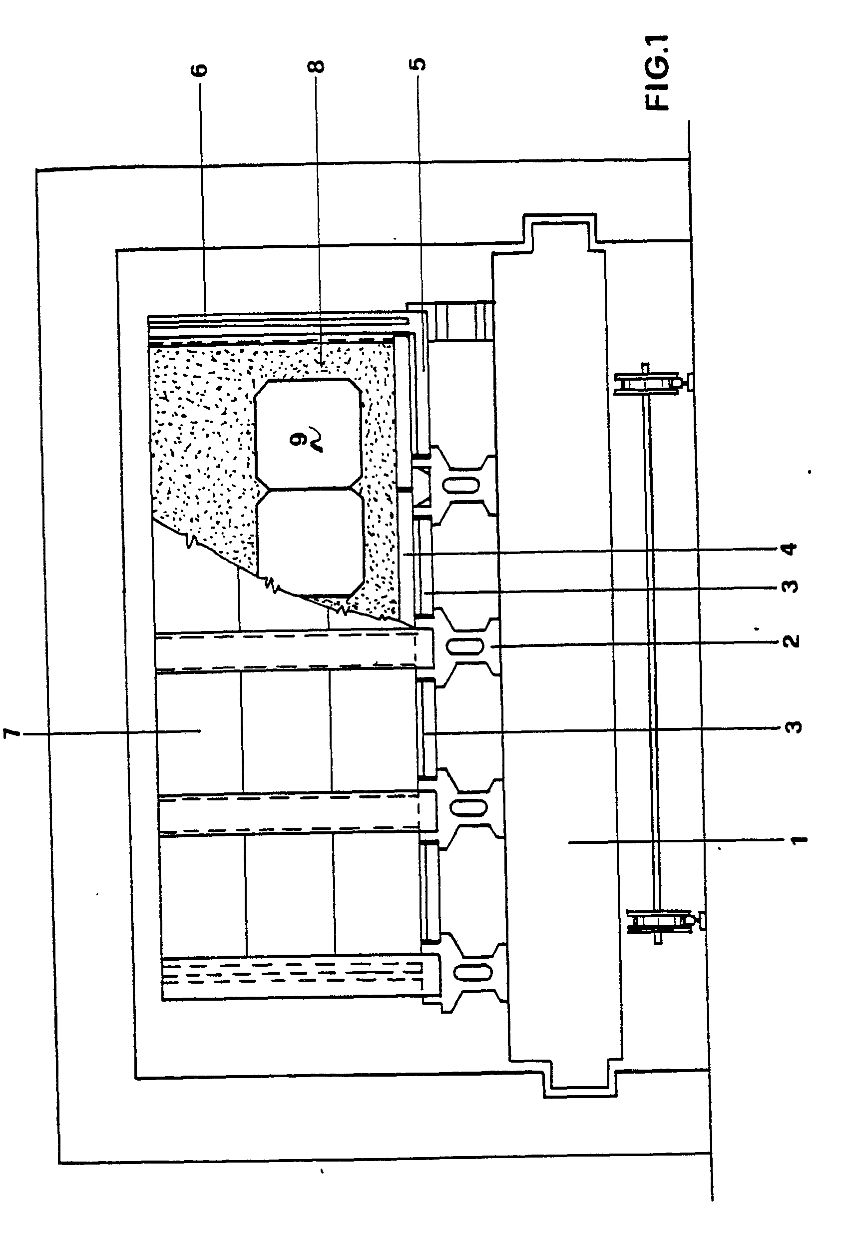
Figure 1 is a partly sectional front view of a containment structure for firing electrodes,
which implements the inventive method;
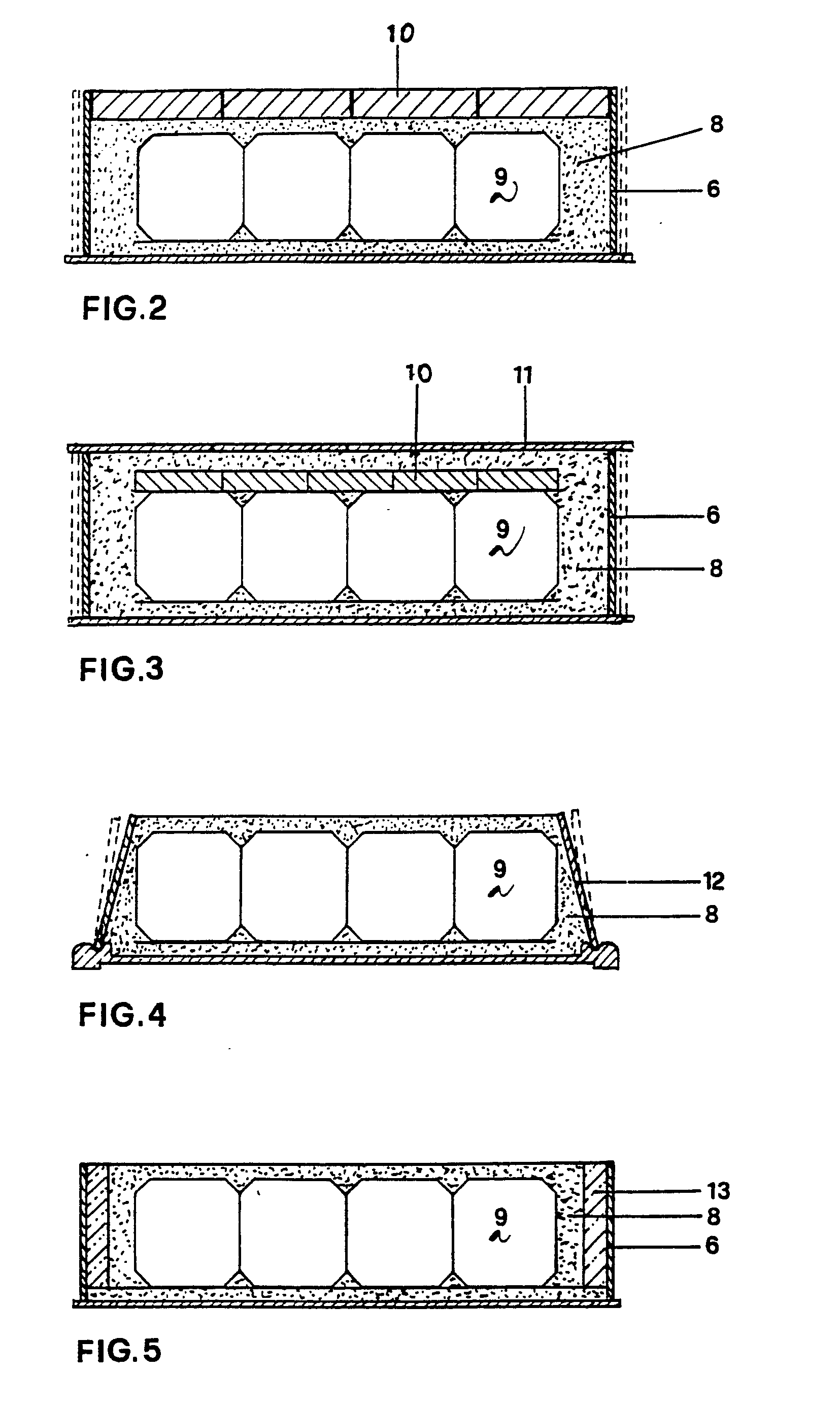
Figure 2 shows schematically in a fragmentary front sectional view, a structure with
the electrodes subjected to the action of weights;
Figure 3 is a view similar to Figure 2, showing a modified embodiment of the structure;
and
Figures 4 and 5 are views similar to Figure 2, showing two further embodiments of
the structure.
[0010] As is apparent from the drawing figures, the method of this invention envisages that
carbonaceous bodies, in particular electrodes, are calcined in a continuous furnace
comprised, in this instance, by a truck furnace on which the electrodes are placed,
preferably in a single layer, although several layers may be viable in some cases.
[0011] Each of the trucks comprises a metal frame 1 on which modular hollow base supports
2 are made to rest which are formed from a refractory material.
[0012] Such base supports 2 are essentially in the form of columns and provided with stepped
grooves adapted to receive beams 3 thereon which form in combination a rest grid for
loading plates 4. Elements 5 rest on the peripheral base supports 2 which extend with
vertical or upstanding pillars 6 provided with longitudinal flutes confronting corresponding
flutes on the adjacent pillars. In essence, the elements 5 resting on the peripheral
base supports 2 form, in combination with the corresponding vertical pillars L-like
elements which carry in pairs plates 7 forming in combination the containment sidewalls
of the truck. The plates 7 are inserted with the vertical sides between confronting
flutes of the pillars 6 and are superimposed to reach a greater combined height than
the carbonaceous bodies to be calcined.
[0013] In particular, the height of the horizontal section of the L-like elements is smaller
than the height of the base support step, thereby said elements are allowed to move
outwards.
[0014] The pillars 6 and plates 7 constitute an edge formation or border which is yieldable
in an outward, lateral direction.
[0015] In operation, a layer of carbonaceous powder 8 is first laid on the loading surface
of a truck, which layer forms the means of protection, for control of oxidation, and
for transmission of expansion in accordance with the invention, and the electrodes
9 to be calcined are then placed onto said layer.
[0016] Thereafter, a filler, again comprised of carbonaceous powder, is poured over said
electrodes which completely covers and surrounds them laterally. The truck is then
moved to the furnace interior to subject the electrodes 9 to the calcining process.
[0017] During calcination, the sidewalls 6 of the truck are allowed to move in a sideways
direction, thus absorbing the thrust from the expanding electrodes as the temperature
rises.
[0018] On leaving the furnace, the original structure of the truck is restored by closing
back the sidewalls, and this operation may be carried out in an automated fashion.
[0019] In a modified embodiment, the inventive method contemplates that a plurality of evenly
distributed weights 10 (see Figure 2) is placed on the filler 8 which comprise, of
preference, corrosion-resistant plates of a refractory material. This arrangement
affords the advantage that, by virtue of the provision of the weights 10 over the
electrodes 9, the thrust from the internal stresses of the latter during the binder
softening phase can be counteracted to prevent their deformation and possible cracking.
[0020] In another embodiment of the invention (see Figure 3), the weights 10 are placed
in direct contact with the top surface of the electrodes 9, and are then covered with
carbonaceous powder. On the layer formed by said powder, there are placed additional
lightweight plates 11 having the function of protecting the powder filler against
oxidation.
[0021] In these embodiments, the sidewalls of the border are allowed to translate outwardly
due to the electrodes expanding.
[0022] In a modified embodiment (see Figure 4), the sidewalls 12 of the border or edge formation
are hinged with their bottom edge to the truck structure and set sloping inwardly
or in any case held close against the filler 8. Thus, upon the electrodes beginning
to expand, the walls can yield sideways and tilt part-way out, thereby the thrusts
brought about by such expansion movements can be absorbed also in this case.
[0023] In a further embodiment (see Figure 5), between the outer walls of the border and
the filler consisting of carbonaceous powder there is interposed a layer of a yieldable
material 13 (e.g. glass wool or some other fibrous material, or polymeric foam, etc.)
having the function of absorbing the expansion of the electrodes during calcination.
The material 13 may either be a plastically or elastically yielding material, or a
heat-destructable one. Depending on the chemical and physical properties of the material
employed, the latter may be used in one or more passages through the furnace interior.
1. A method of calcining carbonaceous bodies, in particular electrodes, in either
continuous or intermittent furnaces by the use of containment structures in which
carbonaceous bodies (9) to be calcined are placed and then covered at least laterally
with a filler as means (8) of protection, for control of oxidation, and for transmission
of expansion, characterized in that at least two sidewalls of the structure are made
to yield sideways outwardly due to the expansion of the carbonaceous bodies during
calcination.
2. A method according to Claim 1, characterized in that the sideways yielding action
is achieved by translation of the containment structure walls in an outward direction.
3. A method according to Claim 1, characterized in that the sideways yielding action
is achieved by tilting the containment structure walls part-way in an outward direction.
4. A method according to Claim 1, characterized in that the sideways yielding action
is achieved by interposing between the sidewalls and the filler a yielding layer.
5. A method according to Claims 1 and 4, characterized in that the sideways yielding
action is achieved by interposing between the sidewalls and the filler an elastically
yielding layer.
6. A method according to Claims 1 and 4, characterized in that the sideways yielding
action is achieved by interposing between the sidewalls and the filler a plastically
yielding layer.
7. A method according to Claims 1 and 4, characterized in that the sideways yielding
action is achieved by interposing between the sidewalls and the filler a layer of
a heat-destructable material.
8. A method according to any of Claims 1 to 7, characterized in that the carbonaceous
bodies (9) are subjected to the action of evenly distributed weights (10) thereover.
9. A method according to Claim 8, characterized in that said weights (10) comprise
a plurality of plates of a refractory material or some other temperature-resisting
material.
10. A method according to Claim 8, characterized in that said weights (10) are laid
directly onto the top surfaces of the carbonaceous bodies.
11. A method according to Claim 10, characterized in that over said weights there
is laid a layer of a material of protection, control of oxidation, and transmission
of expansion, and that an additional covering is placed on said layer for the protection
thereof.
12. A method according to one or more of Claims 1 to 11, characterized in that the
layer of protective, oxidation control, and expansion transmission material comprises
carbonaceous powder.
13. A containment structure for use with either continuous or intermittent furnaces
to implement the method according to one or more of Claims 1 to 12, characterized
in that it comprises a base frame (1), refractory supports (2) placed on said frame
(1) and carrying refractory plates (3) adapted to form a loading surface and a laterally
yieldable border upon said carbonaceous bodies expanding.
14. A containment structure according to Claim 13, characterized in that said border
is formed with refractory pillars (6) provided with mutually confronting flutes for
the insertion of modular refractory plates (7) therein.
15. A structure according to Claim 13, characterized in that said base frame (1) is
wheel mounted.
16. A structure according to Claim 13, characterized in that said border has sidewalls
(12) pivotally connected at the bottom to said base frame.
17. A structure according to Claim 13, characterized in that the sidewalls of said
border are formed in two layers, the inner layer (13) comprising an elastically yieldable
material.
18. A structure according to Claim 13, characterized in that the sidewalls of said
border are formed in two layers, the inner layer comprising a plastically yieldable
material.
19. A structure according to Claim 13, characterized in that the sidewalls of said
border are formed in two layers, the inner layer being heat-destructable at operating
temperatures.
1. Verfahren zum Kalzinieren von Kohlenstoffkörpern, insbesondere von Elektroden,
in entweder kontinuierlichen oder diskontinuierlichen Brennöfen, unter Verwendung
von Behälteranordnungen, in denen die zu kalzinierenden Körper (9) angeordnet und
sodann wenigstens seitlich mit einem Schutzfüllstoff für die Kontrolle der Oxidation
und zur Weiterleitung der Ausdehnung abgedeckt werden, dadurch gekennzeichnet, daß
wenigstens zwei Seitenwände der Umhüllungsanordnung derart ausgebildet sind, daß sie
auf Grund der Ausdehnung der Kohlenkörper während des Kalzinierens seitwärts nach
außen nachgeben.
2. Verfahren nach Anspruch 1, dadurch gekennzeichnet, daß die seitliche nachgebende
Wirkung durch Verschiebung der Wände der Behälteranordnung in Richtung nach außen
erzielt wird.
3. Verfahren nach Anspruch 1, dadurch gekennzeichnet, daß die seitlich nachgebende
Wirkung durch teilweises Kippen der Wände der Behälteranordnung in Richtung nach außen
erzielt wird.
4. Verfahren nach Anspruch 1, dadurch gekennzeichnet, daß die seitlich nachgebende
Wirkung durch Einsetzen einer nachgiebigen Schicht zwischen den Seitenwänden und dem
Füllmaterial erzielt wird.
5. Verfahren nach den Ansprüchen 1 und 4, dadurch gekennzeichnet, daß die seitlich
nachgebende Wirkung durch Einsetzen einer elastisch nachgiebigen Schicht zwischen
den Seitenwänden und dem Füllmaterial erzielt wird.
6. Verfahren nach den Ansprüchen 1 und 4, dadurch gekennzeichnet, daß die seitlich
nachgebende Wirkung durch Einsetzen einer plastisch nachgiebigen Schicht zwischen
den Seitenwänden und dem Füllmaterial erzielt wird.
7. Verfahren nach den Ansprüchen 1 und 4, dadurch gekennzeichnet, daß die seitlich
nachgebende Wirkung durch Einsetzen einer Schicht aus durch Hitze zerstörbarem Material
zwischen den Seitenwänden und dem Füllmaterial erzielt wird.
8. Verfahren nach einem der Ansprüche 1 bis 7, dadurch gekennzeichnet, daß die Kohlekörper
(9) der Wirkung von auf ihnen gleichmäßig verteilten Gewichten (10) ausgesetzt werden.
9. Verfahren nach Anspruch 8, dadurch gekennzeichnet, daß die Gewichte (10) aus einer
Vielzahl von Platten aus hitzefestem Material oder einem anderen temperaturfesten
Material bestehen.
10. Verfahren nach Anspruch 8, dadurch gekennzeichnet, daß die Gewichte (10) direkt
auf die Oberseite der Kohlenkörper aufgelegt werden.
11. Verfahren nach Anspruch 10, dadurch gekennzeichnet, daß auf die Gewichte eine
Schicht aus Material zum Schutz, zur Kontrolle der Oxidation und zur Übertragung der
Ausdehnung aufgelegt und auf diese Schicht einen weiteren Belag zu deren Schutz aufgelegt
wird.
12. Verfahren nach einem oder mehreren der Ansprüche 1 bis 11, dadurch gekennzeichnet,
daß die Schicht aus dem Material zum Schutz, zur Kontrolle der Oxidation und zur Übertragung
der Ausdehnung aus Kohlepulver besteht.
13. Behälter anordnung zur Verwendung in entweder kontinuierlichen oder diskontinuierlichen
Brennöfen zur Durchführung des Verfahrens nach einem oder mehreren der Ansprüche 1
bis 12, dadurch gekennzeichnet, daß sie aus einem Basisrahmen (1), hitzefesten Abstützungen
(2), die auf dem Rahmen (1) angeordnet sind und hitzefeste Platten (3) tragen, die
eine Ladefläche bilden, und einer seitlich nachgiebigen Begrenzung an den sich ausdehnenden
Kohlekörpern besteht.
14. Behälter .anordnung nach Anspruch 13, dadurch gekennzeichnet, daß die Begrenzung
aus hitzefesten Säulen (6) besteht, die mit einander gegenüberstehenden Auskehlungen
zum Einsetzen von hitzefesten Modulplatten (7) versehen sind.
15. Behälteranordnung nach Anspruch 13, dadurch gekennzeichnet, daß der Basisrahmen
(1) auf Rädern montiert ist.
16. Behälteranordnung nach Anspruch 13, dadurch gekennzeichnet, daß die Begrenzung
Seitenwände (12) besitzt, die schwenkbar mit dem Boden des Basisrahmens verbunden
ist.
17. Behälteranordnung nach Anspruch 13, dadurch gekennzeichnet, daß die Seitenwände
der Begrenzung zweischichtig ausgebildet sind, wobei die innere Schicht (13) aus einem
elastisch nachgiebigen Material besteht.
18. Behälteranordnung nach Anspruch 13, dadurch gekennzeichnet, daß die Seitenwände
der Begrenzung zweischichtig ausgebildet sind, wobei die innere Schicht aus einem
plastisch nachgiebigen Material besteht.
19. Behälteranordndung nach Anspruch 13, dadurch gekennzeichnet, daß die Seitenwände
der Begrenzung zweischichtig ausgebildet sind, wobei die innere Schicht bei den Betriebstemperaturen
durch Hitze zerstörbar ist.
1. Méthode de calcination des corps carbonés, en particulier des électrodes en fourneaux
continus ou intermittents à l'aide de structures de confinement dans lesquelles les
corps carbonés (9) devant être calcinés sont placés et ensuite recouverts au moins
latéralement d'une charge comme moyen (8) de protection, pour contrôler l'oxydation,
et pour transmettre l'expansion, caractérisé en ce qu'au moins deux parois latérales
de la structure sont faites pour céder latéralement vers l'extérieur en raison de
l'expansion des corps carbonés pendant la calcination.
2. Méthode selon la revendication 1, caractérisée en ce que l'effet de flexibilité
latérale est réalisé par la translation des parois de la structure de confinement
vers l'extérieur.
3. Méthode selon la revendication 1, caractérisée en ce que l'effet de flexibilité
latéralé est obtenu par inclinaison partielle des parois de la structure de confinement
vers l'extérieur.
4. Méthode selon la revendication 1, caractérisée en ce que l'effet de flexibilité
latérale est obtenu en intercalant une cuche flexible entre les parois latérales et
la charge.
5. Méthode selon les revendications 1 et 4, caractérisé en ce que l'effet de flexibilité
latérale est obtenu en intercalant entre les parois latérales et la charge une couche
flexible agissant de manière élastique.
6. Méthode selon les revendications 1 et 4, caractérisée en ce que l'effet de flexibilité
latérale est obtenu en intercalant entre les parois latérales et la charge une couche
flexible agissant de manière plastique.
7. Méthode selon les revendications 1 et 4, caractérisée en ce que l'effet de flexibilité
latérale est obtenu en intercalant entre les parois latérales et la charge une couche
d'un matériau destructible à la chaleur.
8. Méthode selon l'une quelconque des revendications 1 à 7, caractérisée en ce que
les corps carbonés (9) sont soumis à l'action de poids (10) répartis également sur
ceux-ci.
9. Méthode selon la revendication 8, caractérisée en ce que lesdits poids (10) comprennent
une multiplicité de plaques d'un matériau réfractaire ou de quelque autre matériau
résistant à la chaleur.
10. Méthode selon la revendication 8, caractérisée en ce que lesdits poids (10) sont
posés directement sur les surfaces supérieures des corps carbonés.
11. Méthode selon la revendication 10, caractérisée en ce que sur lesdits poids est
disposée une couche d'un matériau de protection, de contrôle d'oxydation, et de transmission
de l'expansion, et en ce que une couverture supplémentaire est placée sur ladite couche
pour en sécurer la protection.
12. Méthode selon l'une au moins des revendications 1 à 11, caractérisée en ce que
la couche de matériau de protection, de contrôle d'oxydation, et de transmission d'expansion
comprend une poudre carbonée.
13. Structure de confinement destinée à être utilisée avec des fourneaux continus
ou intermittents pour la mise en oeuvre de la méthode selon une au moins des revendications
1 à 12, caractérisée en ce qu'elle comprend une base (1), des supports réfractaires
(2) placés sur ladite base (1) et portant des plaques réfractaires (3) adaptées de
manière à former une surface portante et une extrémité déformable latéralement sous
l'effect de l'expansion desdits corps carbonés.
14. Structure de confinement selon la revendication 13, caractérisée en ce que ladite
extrémité est formée par des colonnes réfractaires (6) munies de rainures se faisant
mutuellement face pour l'insertion de plaques modulaires réfractaires (7).
15. Structure selon la revendication 13, caractérisée en ce que ladite base (1) est
montée sur des roues.
16. Structure selon la revendication 13, caractérisée en ce que ladite extrémité comporte
des parois latérales (12) reliées de manière pivotante à la partie inférieure de ladite
base.
17. Structure selon la revendication 13, caractérisée en ce que les parois latérales
de ladite extrémité sont formés en deux couches, la couche interne (13) comprenant
un matériau deformable de manière élastique.
18. Structure selon la revendication 13, caractérisée en ce que les parois latérales
de ladite extrémité sont formées en deux couches, la couche interne comprenant un
matériau déformable de manière plastique.
19. Structure selon la revendication 13, caractérisée en ce que les parois latérales
de ladite extrémité sont formées en deux couches, la couche interne étant destructible
à la chaleur aux températures de fonctionnement.