| (19) |
 |
|
(11) |
EP 0 180 166 B1 |
| (12) |
EUROPEAN PATENT SPECIFICATION |
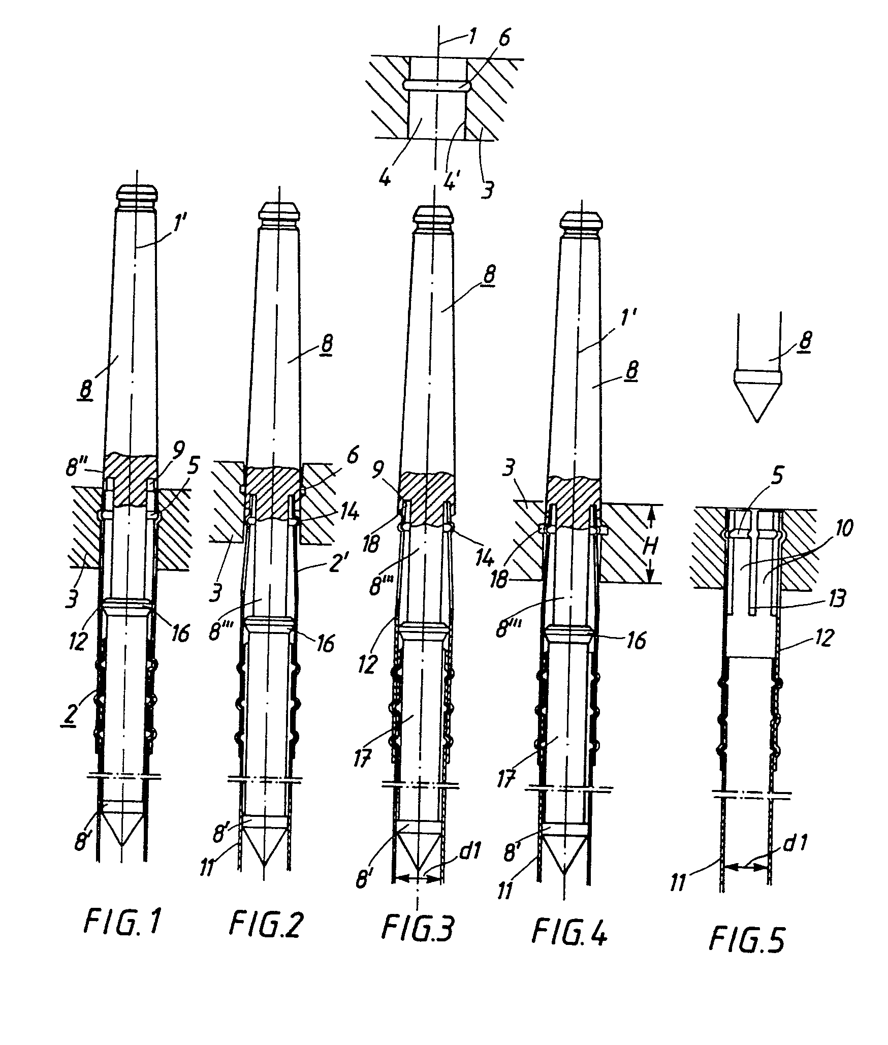
| (45) |
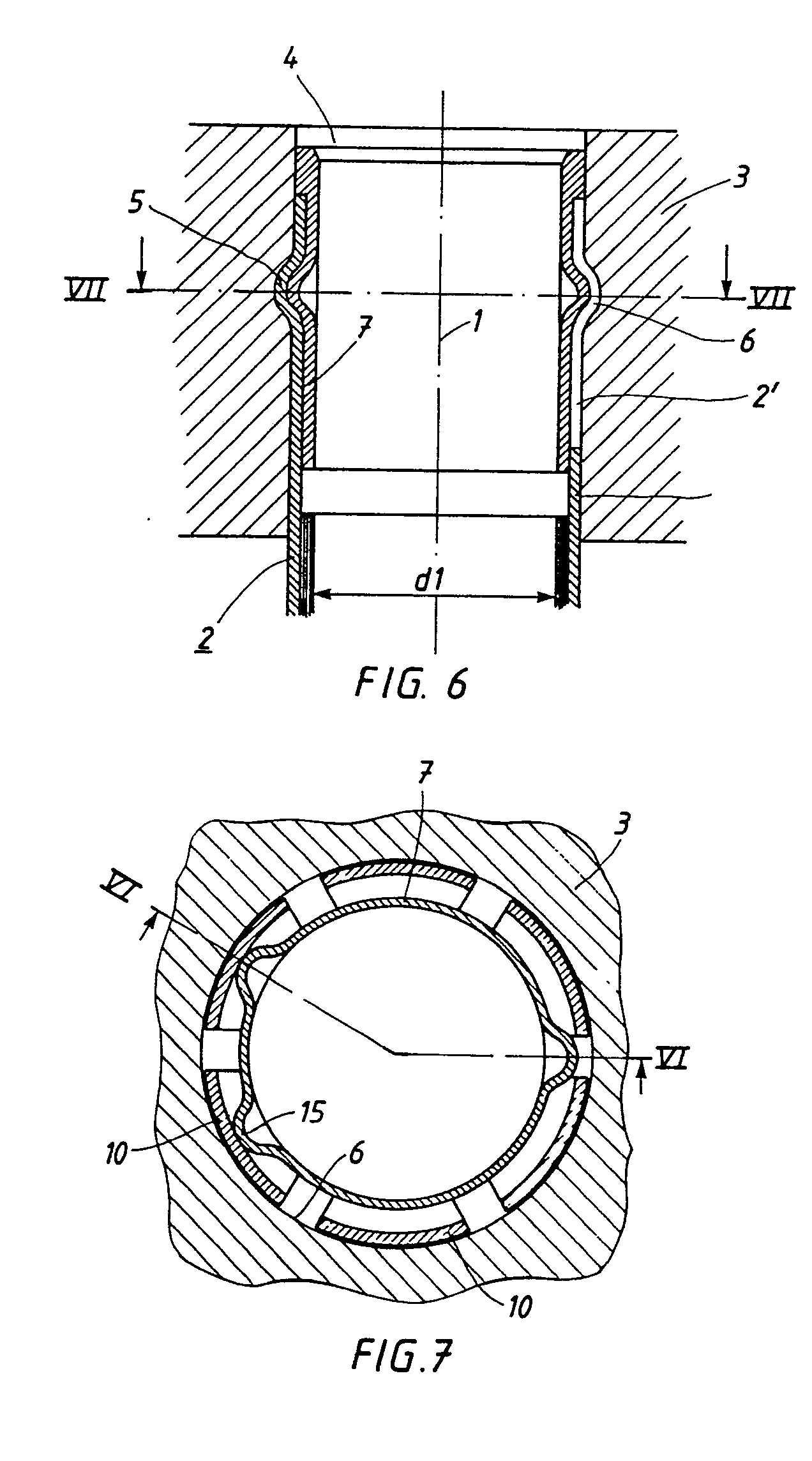
Mention of the grant of the patent: |
|
25.07.1990 Bulletin 1990/30 |
| (22) |
Date of filing: 26.10.1985 |
|
| (51) |
International Patent Classification (IPC)5: G21C 3/32 |
|
| (54) |
A method for protecting the guide tube members of a nuclear fuel assembly and guiding
pin for carrying out the method
Verfahren zum Führungsrohrteilenschutz eines Kernbrennstoffbündels und Führungswerkzeug
zur Ausführung des Verfahrens
Procédé de protection des parties du tube de guidage d'un assemblage de combustible
nucléaire et outil de guidage pour la mise en oeuvre de ce procédé
|
| (84) |
Designated Contracting States: |
|
BE DE FR |
| (30) |
Priority: |
02.11.1984 SE 8405509
|
| (43) |
Date of publication of application: |
|
07.05.1986 Bulletin 1986/19 |
| (73) |
Proprietor: AB ASEA-ATOM |
|
S-721 83 Västeras (SE) |
|
| (72) |
Inventors: |
|
- Almén, Olle
S-722 25 Västeras (SE)
- Collin, Per
S-722 41 Västeras (SE)
|
| (74) |
Representative: Boecker, Joachim, Dr.-Ing. |
|
Adelonstrasse 58
65929 Frankfurt am Main
65929 Frankfurt am Main (DE) |
| (56) |
References cited: :
EP-A- 0 098 774
DE-A- 2 308 800
|
EP-A- 0 140 588
FR-A- 2 533 741
|
|
| |
|
|
|
|
| |
|
| Note: Within nine months from the publication of the mention of the grant of the European
patent, any person may give notice to the European Patent Office of opposition to
the European patent
granted. Notice of opposition shall be filed in a written reasoned statement. It shall
not be deemed to
have been filed until the opposition fee has been paid. (Art. 99(1) European Patent
Convention).
|
[0001] The invention relates to a method for protecting the guide tube members of a nuclear
fuel assembly according to the precharacterising part of claim 1. A nuclear fuel assembly
for which this method can be used is known, for example, from FR-A-2 529 704.
[0002] In the fuel assembly disclosed in the aforementioned publication the slitted end
portions of the guide members are very vulnerable. By the slitting of said end portion
a plurality of axially directed flaps are formed, which can easily be broken when
the slitted portion is not in its place in the top tie plate, that is, during removal
and reinstallation of the top tie plate, and at intermediate stages.
[0003] The invention aims at developing a method of the above-mentioned kind which provides
good protection for the axially directed flaps or fingers of the guide tube member
during removal and reinstallation of the top tie plate and during intermediate storage
of a guide tube member without demanding time consuming special measures having to
be taken.
[0004] In order to achieve this aim the invention suggests a method according to the introductory
part of claim 1, which is characterized by the features of the characterizing part
of claim 1.
[0005] A guiding pin for carrying out the method according to the invention is characterized
by the features of claim 3.
[0006] The invention will now be described in greater detail with reference to the accompanying
drawings showing in
Figures 1-5 a guide tube member in partial vertical section through the centre axis
of a substantially cylindrical through-hole in a top tie plate included in a nuclear
fuel assembly designed for a pressurized water reactor, whereby the different figures
show in numerical order for one and the same guide tube member the consecutive stages
during the removal and reinstallation of the top tie plate;
Figure 6 in vertical section along line VI-VI in Figure 7 an upper end portion of
the same guide tube member prior to removal or after reinstallation of the top tie
plate;
Figure 7 a partial horizontal section along line VII-VII in Figure 6.
[0007] In the drawings, 3 designates a top tie plate in a fuel assembly for a pressurized
water reactor. The top tie plate has a plurality of substantially cylindrical through-holes
4 with a vertical centre axis 1. A guide tube member 2 for a control rod pin is inserted
with an upper end portion into each through-hole 4. The guide tube member 2 has a
vertical centre axis 1' and contains a guide tube 11 with an inner diameter d1, and
a top sleeve 12. The lower top sleeve portion surrounds the upper end portion of the
guide tube 11 and is fixed thereto. In normal condition the top sleeve 12 is inserted
into a through-hole 4 provided in the top tie plate 3. The substantially circular-cylindrical
wall 4' of this through-hole is provided with a horizontal, annular slot 6. The upper
end portion of the top sleeve 12 is provided with six vertical slits 13 being substantially
evenly distributed along the circumference of the sleeve. The sleeve portions which
are located between the slits have a substantially constant wall thickness and form
six resilient fingers 10. Each finger 10 has a circle arc-shaped, radial projection
14 with a radially outwardly facing surface of a convex, double-curved shape and a
radially inwardly facing surface of a concave, double-curved shape. Together, these
projections 14 form a substantially annular sleeve portion 5, divided into annular
segments having a double-curved, convex, radially outward facing surface and a double
curved, concave radially inward facing surface. When inserting a guide tube member
2 into a corresponding through-hole 4, the fingers 10 are first bent resiliently inwardly
and then - when their circle arc-shaped projections arrive at the level of the annular
slot 6 - move back radially outwardly thus causing the above-mentioned, substantially
annular portion 5 of the top sleeve 12 - which portion is divided into annular segments
and has a relatively large outer diameter - to snap into the slot 6. The sleeve portion
5, preferably the entire top sleeve 12, has a substantially constant wall thickness.
The top sleeve 12 is made from a thin-walled, metallic tube material, for example
a tube produced by rolling or drawing.
[0008] For the purpose of retaining the annular sleeve portion 5 of the top sleeve 12 in
the slot 6, a metallic, substantially hollow-cylindrical locking sleeve 7 with a substantially
constant wall thickness is inserted into the top sleeve 12 without any significant
play. The locking sleeve 7 is fixed in the axial direction by means of at least one
bulging or projecting part which is arranged in engagement with the concave side of
the annular sleeve portion 5 of the top sleeve 12. The projecting part of the locking
sleeve 7 may be annular or may consist of at least one wart embossed in the wall of
the locking sleeve 7. In the embodiment shown in Figures 6 and 7, three radially outwardly
directed warts 15 are embossed in the wall of the locking sleeve 7 by means of an
expansion tool which is inserted into the locking sleeve 7 when the latter has been
inserted into the top sleeve 12. The locking sleeve 7 may be made from a material
the ductility of which is either considerably higher than or equal with the ductility
of the material from which the top sleeve 12 is made. In the latter case the locking
sleeve may consist of the same material as the top sleeve 12, with the average wall
thickness of the locking sleeve being chosen preferably smaller than 80 % of the average
wall thickness of the top sleeve 12. When the top tie plate 3 is to be removed - for
example, for the purpose of inserting new fuel rods - the locking sleeve 7 must first
be withdrawn. This involves a destructive deformation of the locking sleeve 7, whereas
the top sleeve 12 remains intact. After the top tie plate 3 has been re-applied, a
new locking sleeve 7 is inserted and expanded. The withdrawal of the locking sleeve
is performed by means of a tool having a plurality of withdrawal hooks and being inserted
into the locking sleeve 7 in such a way that the withdrawal hooks engage with the
lower end surface of the locking sleeve 7.
[0009] In a method according to the invention, the locking sleeve 7 in each one of the guide
tube members 2 is first removed. Thereafter, a corresponding guiding pin 8 is inserted
into each of the holes 4, said guiding pin being oriented in the direction of the
guide tube 11. The guiding pin 8 has a lower circular-cylindrical portion 8', an upper
circular cylindrical portion 8", and a relatively thin, intermediate circular-cylindrical
portion 8"', which is positioned immediately adjacent to the upper portion 8". The
portion 8"' has an axial length which is preferably longer than the thickness H of
the top tie plate 3 and shorter than 3H. Further, the guiding pin 8 is formed with
a circular-cylindrical flange 16, located immediately below the relatively thin portion
8"'. The portions 8", 8' and the flange 16 are dimensioned with such maximum diameters
as to be able to be inserted with slip fit into the hole 4, into the guide tube 11,
and into the top sleeve 12, respectively. A circular cylindrical part 17 of the guiding
pin 8, located between the flange 16 and the lower portion 8', has a diameter which
is somewhat smaller than the maximum diameter of the lower portion 8' but larger than
the diameter of the relatively thin portion 8"'.
[0010] The upper portion 8" has a horizontal annular end surface 18, in which an annular,
downwardly-facing slot 9 is provided. The radially inner wall of this slot 9 consists
of an extension of the circular-cylindrical surface of the relatively thin portion
8' ' ' .
[0011] During the above-mentioned insertion of a guiding pin 8 into each one of the through-holes
4 (see Figures 1-5), the downwardly-facing annular surface 18 of each guiding pin
is first brought into contact with the upper end surfaces of the fingers 10. Thereafter,
the top tie plate 3 is lifted. This movement causes the fingers 10 of each guide tube
member 2 to be bent resiliently radially inwards by the fact that the annular protrusion
5 is forced out of the slot 6. When the contact between the surface 18 and the end
surfaces of the fingers 10 is broken, the guiding pin 8 falls down, and the end portions
of the fingers 10 slip into the annular slot 9 (Figure 2). The fingers 10 maintain
this position in relation to the slot 9 during the continued lifting of the top tie
plate 3 to a level above the upper ends of the guiding pins 8, and also after the
top tie plate 3 has been removed as well as during subsequent corrective maintenance
- for example, exchange of fuel rods - and as well during the reinstallation of the
top tie plate 3. Thus the delicate slitted part of each of the top sleeves 12 is well
protected against contact with the lifting devices used during the repair work and
the components handled by said lifting devices. During reinstallation, the top tie
plate 3 is lowered down towards all the guide tube members 2 while at the same time
these members are to be guided into a respective through-hole 4. This is done without
difficulty since each guiding pin 8 - above the slot 9 - tapers in the direction towards
its upper end. When the top tie plate during its reinstallation has been brought approximately
into its normal position in relation to the guide tube members 2 - as shown in Figure
4 - all the guiding pins 8 are removed, whereafter the radially outwardly protruding
sleeve portion 5 of each guide tube member 2 snaps into a corresponding slot 6. Finally,
a new locking sleeve 7 is inserted into each one of the guide tube members 2 and is
fixed in the same way as the original one.
1. A method for protecting the guide tube members (2) of a nuclear fuel assembly during
removing and/or reinstalling of the top tie plate (3) of the fuel assembly and/or
during intermediate stages, said guide tube members (2) having a vertical centre axis
(1) and a circular cross-section, and being each inserted, with a slitted upper end
portion (2'), in a withdrawable manner into a respective, substantially circular-cylindrical
through-hole (4) in said top. tie plate (3), said slitted end portion having an annular
protrusion (5) adapted to snap into an annular slot (6) provided in the wall of said
through-hole (4), said end portion being locked in said snapped position by means
of a locking sleeve (7) inserted in the end portion, characterized in that for removing
the top tie plate from the guide tube members the locking sleeves (7) are first removed,
that thereafter a guiding pin (8) oriented in the direction of the guide tube (11)
is inserted from above into each one of said through-holes (4), said guiding pin being
formed with a lower portion (8'), an upper portion (8"), and an intermediate, relatively
thin portion (8"') located immediately adjacent to said upper portion, said upper
portion (8") and said lower portion (8') being dimensioned to be inserted with slip
fit into said through-hole (4) and into said guide tube member (2), respectively,
said intermediate portion (8"'), at least in the vicinity of said upper portion, having
a diameter that is by so much smaller than the inner guide tube diameter (d1) as to
allow the adjacent upper portion (8") to be formed with an annular, downwardly facing
surface (18) in which an annular, downwardly facing slot (9) is provided large enough
to allow the insertion of said slitted upper end portion 2', that the insertion of
the guiding pin (8) from above into said through-hole (4) is blocked by contact made
between said downwardly facing surface (18) of the guiding pin (8) and the upwardly
facing surfaces of a plurality of axially directed fingers (10) formed by said slitted
end portion of the guide tube member (2) located in the through-hole, that thereafter
said top tie plate (3) is lifted and said fingers (10) - because said annular protrusion
(5) leaves said annular slot (6) - are bent radially inwardly and are inserted with
their ends into said annular, downwardly facing slot (9) and are held in position
in said slot during the continued removal of the top tie plate (3) in relation to
said guide tube member (2).
2. A method according to claim 1, characterized in that, after the top tie plate has
been removed, the guiding pins are further held in their position relative to their
corresponding guide tube members (2) until the reinstallation of the top tie plate
and up to the point where a normal relation between the top tie plate (3) and the
guide tube members (2) is restored, that the guiding pins (8) are then removed, and
that each one of said slitted guide tube portions (2') is again provided with a corresponding
locking sleeve (7).
3. A guiding pin for carrying out the method according to claim 1 or 2, characterized
in being formed with a lower portion (8'), an upper portion (8"), and an intermediate,
relatively thin portion (8"') located immediately adjacent to said upper portion,
said upper portion (8") and said lower portion (8') being dimensioned to be inserted
with slip fit into said through-hole (4) of the top tie plate and into said guide
tube member (2), respectively, said intermediate portion (8"'), at least in the vicinity
of said upper portion, having a diameter that is by so much smaller than the inner
guide tube diameter (d1) as to allow the adjacent upper portion (8") to be formed
with an annular, downwardly facing surface (18) in which an annular, downwardly facing
slot (9) is provided large enough to allow the insertion the slitted upper end portion
2' of the guide tube member.
1. Verfahren zum Schutz der Führungsrohrglieder (2) eines nuklearen Brennelementbündels
während der Wegnahme und/oder der Wiederanbringung der oberen Verbundplatte (3) des
Brennelementbündels und/oder während dazwischen liegender Zustände, wobei die genannten
Führungsrohrglieder (2) eine vertikale zentrale Achse (1) und einen kreisförmigen
Querschnitt haben und jedes mit einem geschlitzten oberen Endabschnitt (2') in einer
zurückziehbaren Weise in ein entsprechendes im wesentlichen kreiszylindrisches durchgehendes
Loch (4) in der oberen Verbundplatte (3) eingeführt ist, wobei ferner der geschlitzte
Endabschnitt einen ringförmigen Vorsprung (5) hat, der so beschaffen ist, daß er in
eine ringförmige Nut (6) in der Wand des durchgehenden Loches (4) einrasten kann,
und wobei der genannte Endabschnitt in der eingerasteten Stellung mittels einer Verschlußhülse
(7) blockiert wird, die in den Endabschnitt eingeschoben ist, dadurch gekennzeichnet,
daß zur Wegnahme der oberen Verbundplatte von den Führungsrohrglieder zunächst die
Verschlußhülse (7) entfernt wird, daß danach von oben her in jedes der durchgehenden
Löcher (4) ein Führungsstift (8), der in Richtung des Führungsrohrs (11) orientiert
ist, eingeführt wird, daß der Führungsstift einen unteren Abschnitt (8') einen oberen
Abschnitt (8") und einen mittleren, relativ dünnen Abschnitt (8"') hat, der unmittelbar
an den oberen Abschnitt anschließt, daß der obere Abschnitt (8") und der untere Abschnitt
(8') so bemessen sind, daß sie mit einem Gleitsitz in das durchgehende (4) bzw. das
Führungsrohrglied (2) einführbar sind, daß der mittlere Abschnitt (8"') zumindest
in der Nähe des genannten oberen Abschnittes einen Durchmesser hat, der um soviel
kleiner ist als der innere Durchmesser (d1) des Führungsrohrs, daß der benachbarte
obere Abschnitt (8") mit einer nach unten gerichteten ringförmigen Fläche (18) versehen
sein kann, in welcher eine nach unten gerichtete ringförmige Nut (9) vorhanden ist,
die groß genug ist, um die Einführung des geschlitzten oberen Enabschnittes (2') zu
ermöglichen, daß die Einführung des Führungsstiftes (8) von oben in das durchgegende
Loch (4) blockiert wird durch Kontakt zwischen der nach unten gerichteten Fläche (18)
des Führungsstiftes (8) und der nach oben gerichteten Fläche einer Vielzahl von achsial
gerichteten Fingern (10), die von dem genannten geschlitzten Endabschnitt des Führungsrohrgliedes
(2), das sich in dem durchgehenden Loch befindet, geformt werden, daß danach die oberen
Verbundplatte (3) abgehoben wird und die Finger (10) - weil der ringförmige Vorsprung
(5) die ringförmige Nut (6) verläßt - radial nach innen gebogen werden und mit ihren
Enden in die nach unten gerichtete Nut (9) einmünden und in dieser Nut während der
weiteren Entfernung der oberen Verbundplatte (3) relativ zum Führungsrohrglied (2)
in ihrer Lage festgehalten werden.
2. Verfahren nach Anspruch 1, dadurch gekennzeichnet, daß nach Entfernung der oberen
Verbundplatte die Führungsstifte weiter in ihrer Position relativ zu den entsprechenden
Führungsrohrgliedern (2) bis zur Wiedereinsetzung der oberen Verbundplatte gehalten
werden, und zwar solange, bis die normale Beziehung zwischen der Verbundplatte (3)
und Führungsrohrglieder (2) wiederhergestellt ist, daß die Führungsstifte (8) dann
entfernt werden und daß jeder der geschlitzten Führungsrohrabschnitte (2') wieder
mit einer entsprechenden Verschlußhülse (7) versehen wird.
3. Führungsstift zur Durchführung des Verfahrens nach Anspruch 1 oder 2, dadurch gekennzeichnet,
daß der Führungsstift einen unteren Abschnitt (8'), einen oberen Abschnitt (8") und
eine mitteleren, relativ dünnen Abschnitt (8" ') hat, welcher unmittelbar an den genannten
oberen Abschnitt anschließt, daß der obere Abschnitt (8") und der untere Abschnitt
(8') so bemessen sind, daß sie mit einem Gleitsitz in das durchgehenden Loch (4) in
der oberen Verbundplatte beziehungsweise das Führungsrohrglied (2) einführbar ist,
daß der mittlere Abschnitt (8"'), zumindest in der Nähe des genannten oberen Abschnittes,
einen Durchmesser hat, der um soviel kleiner ist als der innere Durchmesser (d1) des
Führungsrohrs, daß der benachbarte obere Abschnitt (8") mit einer nach unten gerichteten
ringförmigen Fläche (18) versehen werden kann, in welcher eine nach unten gerichtete
Nut (9) vorhanden ist, die groß genug ist, um die Einführung des geschlitzten oberen
Endabschnittes des Führungsrohrgliedes zu ermöglichen.
1. Procédé de protection des tubes-guides (2) d'un assemblage combustible de réacteur
nucléaire pendant le démontage et/ou le remontage de la plaque supérieure de fixation
(3) de l'assemblage combustible et/ou pendant des stades intermédiaires, ces tubes-guides
(2) ayant un axe (1) vertical et une section transversale circulaire et étant chacun
insérés, par une partie supérieure d'extrémité (2') fendue, d'une manière amovible,
dans un trou traversant (4) cylindrique de section transversale sensiblement circulaire,
ménagé dans la plaque supérieure de fixation (3) cette partie d'extrémité fendue ayant
une partie saillante (5) annulaire destinée à s'encliqueter dans une gorge (6) annulaire
ménagée dans la paroi du trou traversant (4), la partie d'extrémité étant bloquée
en la position encliquetée au moyen d'une douille de blocage (7) insérée dans la partie
d'extrémité, caractérisé en ce que, pour enlever la plaque supérieure de fixation
des tubes-guides, on enlève d'abord les douilles de blocage (7), on enfile ensuite
une tige de guidage (8) orientée dans la direction du tube-guide (11) par le haut
dans chacun des trous traversant (4), la tige-guide étant formée d'une partie inférieure
(8') d'une partie supérieure (8") et d'une partie intermédiaire (8"') relativement
mince et immédiatement adjacente à la partie supérieure, la partie supérieure (8")
et la partie inférieure (8') ayant des dimensions telles qu'elles peuvent être insérées
avec un jeu glissant dans le trou traversant (4) et dans le tube-guide (2) respectivement,
la partie intermédiaire (8"') ayant, au moins à proximité de la partie supérieure,
un diamètre qui est tellement plus petit que le diamètre intérieur (d1) du tube guide,
qu'il permet à la partie supérieure (8") adjacente d'avoir une surface (18) annulaire
tournée vers le bas dans laquelle est ménagée une gorge (9) annulaire tournée vers
le bas, suffisamment grande pour permettre l'insertion de la partie supérieure d'extrémité
(2') fendue, l'insertion de la tige de guidage (8) par le haut dans le trou traversant
(4) étant bloquée par le contact entre la surface (18) tournée vers le bas de la tige
de guidage (8) et les surfaces tournées vers le haut de plusieurs doigts (10) dirigés
axialement et formés par la partie d'extrémité fendue du tube-guide (2) placé dans
le trou traversant, et ensuite on soulève la plaque supérieure de fixation (3) et
les doigts (10) - la partie saillante (5) annulaire quittant la gorge (6) annulaire
- sont courbés radialement vers l'intérieur et sont insérés par leur extrémité dans
la gorge (9) annulaire tournée vers le bas et sont maintenus en position dans cette
gorge tant que la plaque supérieure de fixation (3) est enlevée du tube-guide (2).
2. Procédé suivant la revendication 1, caractérisé en ce qu'après avoir enlevée la
plaque supérieure de fixation, on maintient encore les tiges de guidage en leur position
par rapport à leur tube-guide (2) correspondant jusqu'au remontage de la plaque supérieure
de fixation et jusqu'au point de rétablissement d'une relation normale entre la plaque
supérieure de fixation (3) et les tubes-guides (2), on enlève ensuite les tiges de
guidage (8) et on munit chacune des parties fendues (2') de tube-guide à nouveau d'une
douille de blocage (7) correspondante.
3. Tige de guidage pour la mise en oeuvre du procédé suivant la revendication 1 ou
2, caractérisée en ce qu'elle est formée d'une partie inférieure (8') d'une partie
supérieure (8") et d'une partie intermédiaire (8"') relativement mince et immédiatement
adjacente à la partie supérieure, la partie supérieure (8") et la partie inférieure
(8') ayant des dimensions qui leur permettent d'être insérées avec jeu glissant dans
le trou traversant (4) de la plaque supérieure de fixation et dans le tube guide (2)
respectivement, la partie intermédiaire (8"') ayant, au moins à proximité de la partie
supérieure, un diamètre qui est tellement plus petit que le diamètre intérieur (d1)
du tube guide qu'il permet de ménager dans la partie supérieure (8") adjacente une
surface (18) annulaire, tournée vers le bas, dans laquelle est prévue une gorge (9)
annulaire, tournée vers le bas, suffisamment grande pour permettre l'insertion de
la partie fendue (2') de l'extrémité supérieure du tube-guide.