|
(11) | EP 0 193 994 A1 |

| (12) | EUROPEAN PATENT APPLICATION |
|
|
|
|
|||||||||||||||||||||||||||
| (54) | Device for gripping in formation a number of objects such as tiles |
| (57) @ Device for gripping in formation a number of objects 1 a... 1 d; 2a...2d; 3a...
3d), such as tiles, lying on either side of both a first (horizontal) reference line
(X) and a second (vertical) reference line (Y) at right angles thereto, with gripper heads (12a... 12d;13a... 13d) procided on
at least one set of radially arranged supporting arms (14a... 14d; 15a... 15d) movable
in the longitudinal direction and, starting with the supporting arms (5) closest to
the second reference line (X), including with the first reference line successive
angles the tangent of which varies according to the series 1, 1 3, 1 5, 1 7 etc.,
while the extent of movement of the respective arms, starting with the supporting
arm closest to the second reference line (Y), is successively equal to: |
[0001] The invention relates to a device for gripping in formation a number of objects, such as tiles, lying on either side of both a first (horizontal) reference line and a second (vertical) reference line at right angles thereto, with gripper heads provided on at least one set of radially arranged supporting arms whose grippers work in conjunction with the tiles lying directly on either side of the first reference line.
[0002] Such a device is known per se from German Utility Model 952,976. For use of this known device, the objects, such as tiles, must be taken, prior to gripping, to the correct distance between them, so that the necessary width of joint is present. This action is time-consuming.
[0003] The object of the invention is to produce a device which provides the possibility of the tiles being arranged lying against each other prior to the gripping, so that they are, for example, in the configuration in which they were sent packed, following which, after the gripper heads grip the tiles, the distance between them required for the width of joint is set by shifting these gripper heads in relation to one another.
[0004] This object is achieved according to the invention in that, for the production of a groove distance (a) between them, the supporting arms are movable in the longitudinal direction and, starting with the supporting arms closest to the second reference line, they include with the first reference line successive angles the tangent of which varies according to the series 1 - 1/3 - 1/5 - 1/7 etc., while the extent of movement of the respective arms, starting with the supporting arm closest to the second reference line, is successively equal to:
[0005] The above-described measures mean that when the supporting arms have carried out the defined respective movements, distances equal to the desired groove distance (a) are created between the tiles.
[0006] It is clear that this measure greatly speeds up working with the device, for there is no need for the time-consuming arrangement of the tiles at the desired distance from one another. Another advantage is that when adhesive has to be applied to the back of the tiles, this can be carried out while the tiles are in a closed formation, so that is avoids adhesive going on the side walls of the tiles.
[0007] An embodiment suitable for gripping more than one row of tiles on either side of the first reference line is characterized in that for each extra set of supporting arms, whose grippers are intended for working in conjunction with further rows of objects adjoining the first rows, the tangents of the respective included angles run in accordance with the said series (1 - 1/3 - 1/5 - 1/7), multiplied by the factor 3, 5 etc., while the extent of movement of the respective arms, starting with the supporting arms closest to the second reference line, is successively equal to:
etc. and
etc.
[0008] Other advantageous embodiments according to the invention are described in the claims which follow.
[0009] The invention is explained with reference to the drawing.
Fig.l shows schematically a number of tiles lying in closed formation on either side of a horizontal and a vertical reference line;
Fig.2 shows these tiles after equal intervals have been produced between them;
Fig.3 shows a top view of an embodiment according to the invention suitable for gripping eight tiles;
Fig.4 is a top view of the operating mechanism thereof;
Fig.5 is a side view of this embodiment.
[0010] In Fig.l, the letter X indicates a first, horizontal, reference line, and the letter Y a second, vertical reference line; the two lines intersect each other at point 0. On either side of both the horizontal reference line X and the vertical reference line Y lie a numer of square objects such as tiles in a closed formation, of which only the tiles in the first quadrant are drawn in, while in the other a number are indicated by dotted lines. In the first row I the tiles are indicated by the reference number la, Ib, lc, ld; on the next row 2 the objects are indicated by 2a, 2b, 2c and 2d, and those of the third row 3 are indicated by 3a-3d. When the invention is used for gripping tiles commonly used for building - thus in the embodiment shown in Fig. 3 to 5 - far fewer objects will, of course, be gripped simultaneously than shown in Fig.l: in general no more than eight.
[0011] As is explained with reference to Fig.2, the device according to the invention is equipped to create a fixed distance - indicated by the letter (a) - between the objects after gripping them. This means that the tiles in row 1 all have to be moved upwards over a distance a/2, and the tiles in the row 1' below the line X have to be moved over the same distance downwards, while in these rows the first tile la has to be moved over a distance a/2 to the right. The second tile lb has to be moved over a distance 3a/2 to the right, the thrid tile lc moved over a distance Sa/2, and the fourth tile ld moved over a distance 7a/2. This movement to the right also applies to the tiles from rows 2 and 3, but the tiles from row 2 all have to be moved upwards over a distance 3a/2, while the tiles from row 3 all have to be moved upwards over a distance 5a/2. Such movements apply, of course, to the rows situated under the X axis.
[0012] According to the invention, this movement takes place by means of radially arranged supporting rods which have gripper heads, and which form different angles with the line X, and all have to be moved over different distances from each other. For the sake of brevity, only the conditions for the supporting rods projecting in the first quadrant will be discussed.
[0013] The angle between each supporting rod and the Y axis is determined on the basis of the fact that the tangent of this angle is equal to the quotient of the movement in the vertical direction and the movement in the horizontal direction of the tile working in conjunction with this supporting rod. As regards the distance over which the supporting rod has to be moved, it is equal to the square root of the sum of the squares of the movements in the X and Y direction respectively. The extent of these movements is shown in Fig.l. So the supporting rod gripping the tile la, indicated in Fig.l by reference number 5, with line X includes an angle 1, whose tangent is equal to a:2/a:2=l. This angle is therefore 45 degrees. The supporting rod 6, whose gripper grips the tile lb, with line X includes an angle α2, whose tangent is equal to a:2/3a:2=1/3; this angle is therefore 18 degrees. The angle α 3 between the supporting rod 7, whose gripper head grips tile lc, has a tangent equal to a:2/5a:2=1/5; x is therefore equal to 11 degrees. As regards the angle α4 between the supporting rod 8 whose gripper head grips tile ld, the tangent is equal to 1/7; this angle is 8 degrees.
[0014] As regards the supporting rods, not shown in the figure, whose gripper heads grip the tiles from row 2, the tangent of the successive included angles varies according to the series 3 - 1 - 3/5 - 3/7, so that the included angles are equal respectively to 71 deg., 45 deg, 31 deg. and 23 deg.. As for row 3, the supporting rods (not shovn) form successive angles whose tangent varies according to the series 5 - 5/3 - 1 - 5/7; so these angles are respectively 78 deg., 59 deg, 45 deg. and 35 deg.
[0015] The distance over which each supporting rod has to be moved has already been defined in the above. In order to achieve a qroove distance (a), the supporting rod 5 must be moved over a distance
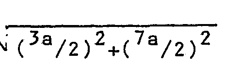
As for the supporting rod 6, this distance is
. The distances over which the other supporting arms have to be moved follow from the movements indicated in the figure in the x and y directions respectively.
[0016] It is pointed out that it is not necessary for the centre lines of the respective supporting rods to pass through the origin, Even if the respective supporting rods are parallel to the lines passing through the origin and meeting the above conditions, the same effect is obtained.
[0017] Figs. 3 to 5 relate to a concrete embodiment of the device according to the invention. This device is equipped to grip simultaneously eight adjacent tiles and produce the desired intervals between them. The tiles 10a...10d and lla...lld are arranged in two rows, 10 and 11. The eight pneumatic gripper heads 12a...l2d, 13a...13d are disposed on the end-of supporting arms 14a...14d, 15a...15d, and these arms are guided so that they slide in a frame 16. This frame 16 has a central shaft 17 with two cam discs 18, 19, of which the disc 18 works in conjunction with the arms 14a, 14c, 15b and 15d, while the top disc 19 works in conjunction with the arms 15a, 14b, 14d and 15c. The cams formed on the discs (the figure shows the cams 19a....19d of the disc 19) have different heights from each other, in order to produce the desired, different movements over the distances described above.
[0018] The frame 16 has two handles; 20, 21, and next to each handle provision is made for an operating handle 24, 25 which rotates about the end of a supporting arm 22 or 23. These handles are connected via pull rods 26, 27 to the end of an operating lever 28, which is fixed on the shaft 17. By seizing one of the handles 24 or 25, it is possible to turn the shaft 17 as desired clockwise or anticlockwise and thus achieve the movement of the supporting arms 14a-14d, 15a-15d.
[0019] Of course, the gripper heads are connected via suitable lines to a central vacuum connection; one of these lines is shown schematically and is indicated by reference number 29; the central vacuum connection is indicated by reference number 30.
[0020] Before the gripper heads are placed on the tiles, the supporting rods are taken to the retracted position by pe- rating the correct handle, and the device is then placed on the tiles. Following that, vacuum suction takes place, so that the gripper heads grip the tiles, and the other handle is then operated, with the result that the desired width of joint is produced between the tiles. The tiles can now be placed on the wall and, after removal of the vacuum, the whole device can be disengaged.
1. Device for gripping in formation a number of objects (la...ld; Za...2d; 3a...3d),
such as tiles, lying on either side of both a first (horizontal) reference line (X)
and a second (vertical) reference line (Y) at right angles thereto, with gripper heads
(12a...12d; 13a...13d) provided on at least one set of radially arranged supporting
arms (14a...14d; 15a...15d) whose grippers work in conjunction with the tiles lying
directly on either side of the first reference line, characterized in that, for the
production of a groove distance (a) between them, the supporting arms are movable
in the longitudinal direction and, starting with the supporting arms (5) closest to
the second reference line (X), they include with the first reference line successive
angles the tangent of shich varies according to the series 1 - 1/3 - 1/5 - 1/7 etc.,
while the extent of movement of the respective arms, starting with the supporting
arm closest to the second reference line (Y), is successively equal to:
2. Device according to Claim 1, characterized in that for each extra set of supporting
arms, whose grippers are intended for working in conjunction with further rows of
objects adjoining the first rows, the tangents of the angles formed respectively run
in accordance with the said series 1 - 1/3 - 1/5 - 1/7, multiplied by the factor 3,
5 etc., while the extent of movement of the respective arms, starting with the supporting
arms closest to the second reference line, is successively equal to:

etc. and


etc.
etc. and
etc.
3. Device according to Claim 1 or 2, characterized by a guide frame (16) in which
the supporting arms are guided in sliding fashion, with in the middle a central control
shaft (17) provided with radial control cams (18, 19) standing crosswise thereon and
acting upon the ends of the supporting arms (14a...14d; 15a...15d).
4. Device according to Claim 3, characterized by two supporting handles (20, 21) provided
on either side of the frame (16), each with an operating handle (24, 25) which via
a pull rod (27, 26) is connected to a lever (28) fixed on the control shaft (17).
5. Device according to Claim 1-4, characterized in that the grippers are formed by
vacuum suction cups.