| (19) |
 |
|
(11) |
EP 0 200 697 B1 |
| (12) |
EUROPEAN PATENT SPECIFICATION |
| (45) |
Mention of the grant of the patent: |
|
06.11.1991 Bulletin 1991/45 |
| (22) |
Date of filing: 18.04.1986 |
|
|
| (54) |
A method and arrangement for recovering fluorescent material from mercury vapour discharge
lamps
Verfahren und Einrichtung zur Rückgewinnung von Fluoreszenzmaterial aus Quecksilberdampfentladungslampen
Méthode et disposition pour régénérer du matériel fluorescent des lampes à décharge
à vapeur de mercure
|
| (84) |
Designated Contracting States: |
|
AT BE CH DE FR GB IT LI LU NL SE |
| (30) |
Priority: |
30.04.1985 SE 8502103
|
| (43) |
Date of publication of application: |
|
05.11.1986 Bulletin 1986/45 |
| (73) |
Proprietor: MRT System Aktiebolag |
|
S-371 50 Karlskrona (SE) |
|
| (72) |
Inventor: |
|
- Kulander, Hans
S-572 00 Oskarshamn (SE)
|
| (74) |
Representative: Norin, Klas et al |
|
Kooperativa förbundet
Patent Department
P.O. Box 15200
104 65 Stockholm
104 65 Stockholm (SE) |
| (56) |
References cited: :
EP-A- 0 157 249
US-A- 3 839 085
|
SU-A- 174 781
|
|
| |
|
|
|
|
| |
|
| Note: Within nine months from the publication of the mention of the grant of the European
patent, any person may give notice to the European Patent Office of opposition to
the European patent
granted. Notice of opposition shall be filed in a written reasoned statement. It shall
not be deemed to
have been filed until the opposition fee has been paid. (Art. 99(1) European Patent
Convention).
|
[0001] The present invention relates to a method for removing and collecting fluorescent
material from mercury vapour electric discharge lamps or like lamps, in which the
ends of the lamp, together with associated contact elements are separated from the
intermediate part of the lamp bulb and the mercury-laden luminescent material is loosened
from the inner surfaces of the intermediate bulb part with the aid of a stripping
device arranged for insertion to said bulb part through one end thereof and in which
the loosened luminescent material is collected with the aid of a suction device which
creates an air stream through the intermediate bulb part.
[0002] The invention also relates to an arrangement for removing and collecting luminescent
material from mercury vapour electrical discharge lamps and like lamps, wherein the
arrangement includes a stripping device which is effective in loosening the luminescent
material from the inner wall surface of a bulb part and a suction device capable of
being connected to one end of the lamp part in order to collect loosened luminescent
material.
[0003] Mercury is a necessary constituent of the fluorescent layer in mercury vapour discharge
lamps. Consequently, extended or burned-out lamps must be processed in a suitable
manner, so that the fluorescent material has no harmful effect on surrounding fauna
and flora. Originally, expended vapour discharge lamps were dumped in the countryside
at convenient dumping locations, although this procedure is now normally forbidden
by the authorities. Controlled storage within the vapour discharge lamp industry has
also become troublesome, due to the large quantities of waste requiring handling and
supervision. In accordance with one practical method proposed some years ago the expended
or scrapped lamps are crushed into fragments, coated with luminescent material, and
the fragments placed in a treatment vessel in which the mercury is recovered by distillation
processes. This treatment is carried out batchwise in a sealed container, into which
nitrogen gas is introduced, and the container heated and placed under vacuum, such
as to vapourize the mercury, the vapourized mercury being removed from the container
through a bottom outlet and condensed in a cooling trap. This method is described
and illustrated in German Published Specification 2911994.6. However, alhough the
mercury is separated very efficiently, the process involved is extremely slow, taking
about 9 hours to complete for each batch of 120 l, which renders the method expensive
and therewith difficult to introduce in all destruction plants or in other establishments
requiring to treat or process scrapped vapour discharge lamps.
[0004] A machine for removing fluorescent coatings from the inside of fluorescent tubes
is disclosed in SU-A-174781. This machine includes a round wire brush for the removement
or loosening of said coatings. The removed material is sucked into openings provided
in a hollow shaft and further out through a rubber hose to a suction apparatus. The
machine will probably clean the bulbs rather effectively but at the price of a comparably
complicated design and a time-consuming method. The brush will soon be worn out and
the rotating machinery needs couplings and other details which have to be maintained.
[0005] Consequently, one object of the present invention is to provide a method and an arrangement
for removing and collecting luminescent material from mercury vapour electric discharge
lamps which are very efficient and easy to introduce in an automatic line for recovering
luminescent material. A second object is to provide a more reliable, faster and simplified
method and arrangement as compared to the prior art. Other objects of the invention
and advantages afforded thereby will be evident from the following description. These
objects and advantages are achieved by the method and arrangement according to the
invention having the characterizing features set forth in the appended claims.
[0006] The invention will now be described in more detail with reference to the accompanying
drawings, in which
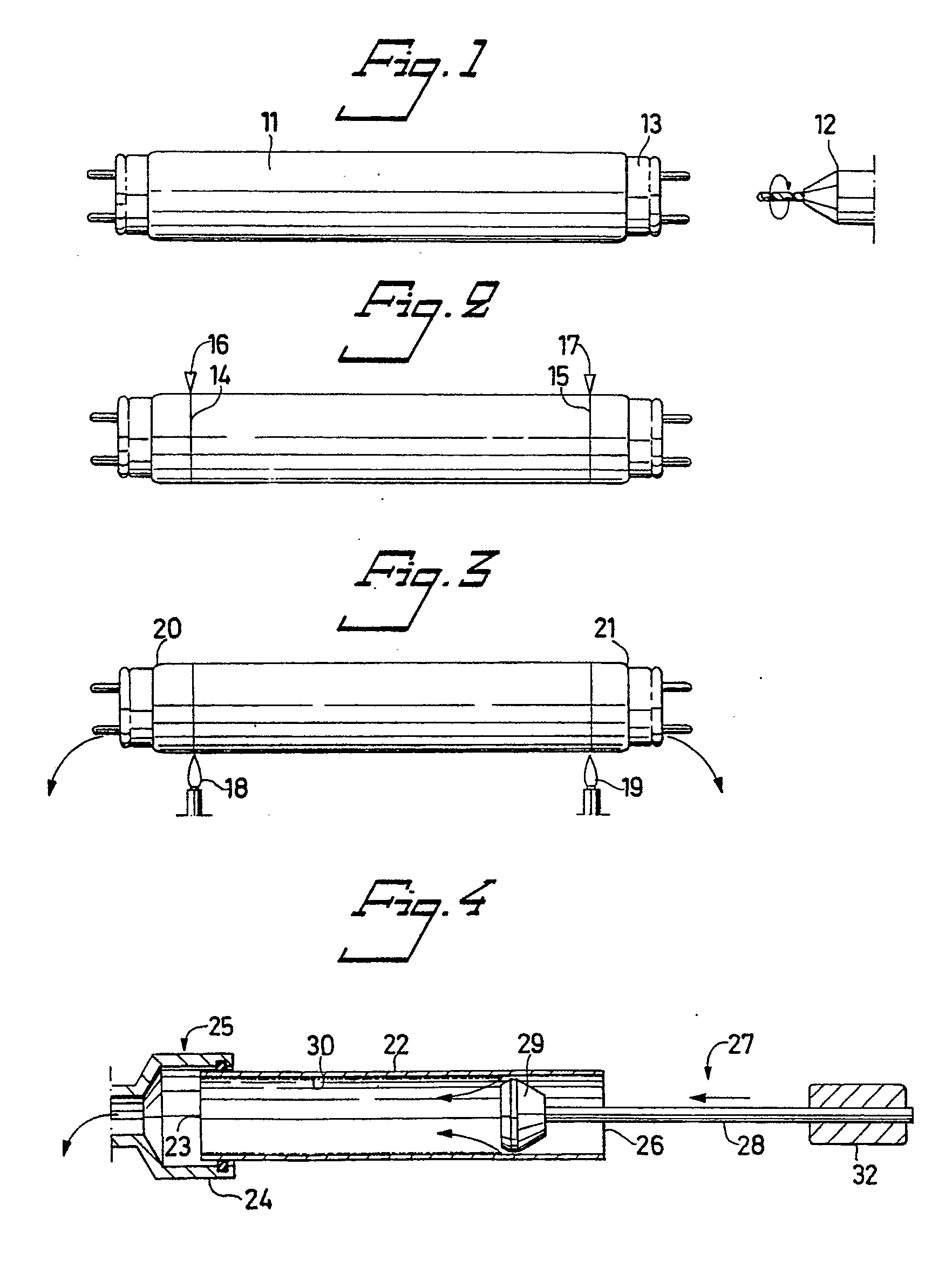
Figures 1 - 3 are respective side views of the bulb section of a mercury vapour electric
discharge lamp, and illustrates schematically the initial stages of a method according
to the invention;
Figure 4 is a schematic, longitudinal sectional view of the intermediate tubular part
of the bulb or tube illustrated in Figures 1 - 3, and illustrates schematically an
arrangement for loosening luminescent material from the intermediate bulb part;
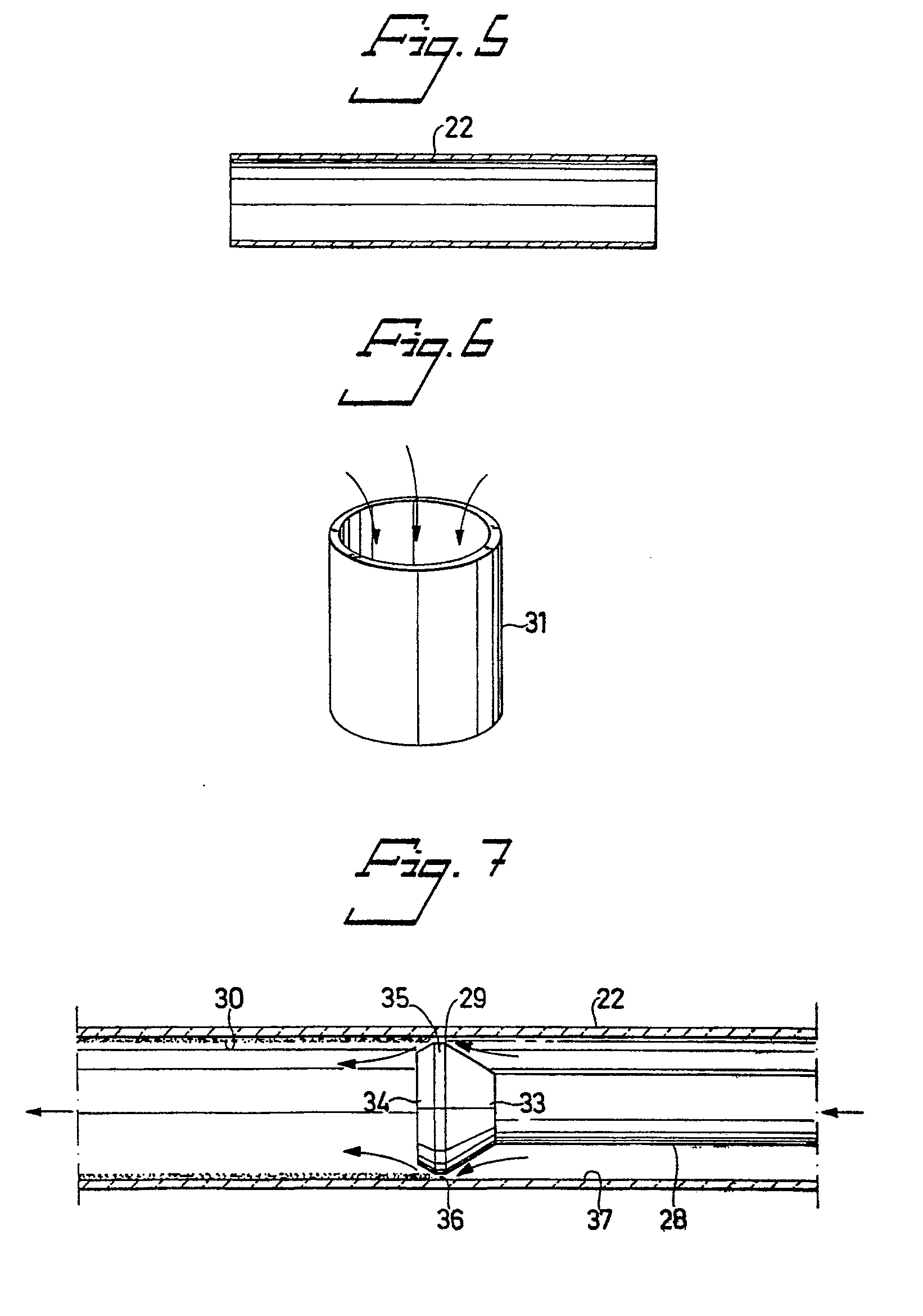
Figures 5 illustrates the intermediate bulb part shown in Figure 4, with the luminescent
material removed therefrom;
Figure 6 illustrates a mercury distillation vessel; and
Figure 7 is an enlarged view of the bulb or tube section illustrated in Figure 4.
[0007] Mercury vapour electric discharge lamps received for treatment in destruction plants
and like centres are normally expended or burnt-out, but otherwise whole. The present
invention is particularly aimed at the treatment of such lamps, and the various stages
of an illustrative method according to the invention will now be described with reference
to the schematic Figures 1 - 6.
a) In order to avoid implosions, the lamp bulb or tube 11 is punctured, preferably
by drilling a hole through the electrical contact element 13 located at one end of
the bulb, with the aid of a drill 12.
b) Score-lines 14,15 are scribed in respective ends of the bulb in some suitable manner,
with the aid of knives 16,17.
c) The scored regions of the bulb are then rapidly heated with gas flames 18,19, to
cause the glass to crack at said regions, thereby enabling the lamp ends 20,21 to
be removed from the bulb or tube 11.
d) One end 23 of the residual bulb part 22 is then connected to a nozzle 24 provided
on a suitable suction device indicated at 25, although not shown in detail. A stripper
device 27 is then inserted into the bulb part 22, through the other end 26 thereof,
the illustrated stripper device having the form of a stripping head 29 which is carried
on a rod 28 and guided in the bulb part 22 in a manner to form an air gap of only
some tenths of a millimetre between a peripheral surface on the stripping head and
the opposing wall of the bulb part 22. The luminescent powder 30 located on the wall
of the bulb part 22 is removed therefrom with the aid of a suction effect created
by an amplified air stream formed around the stripping head 29, and is collected in
the suction device 25.
e) The cleansed bulb part 11, no longer contaminated with mercury, is now removed
and may be used again in a new vapour electric discharge lamp.
f) The ends 20,21 of the lamp and the collected luminescent powder are now placed
in a treatment chamber 31, for distillation of the mercury present in a known manner.
[0008] This method enables the bulb part 22 to be removed from the process prior to distillation,
which means that ten times as much discharge-lamp waste material can be treated in
comparison with processes in which the bulbs are first crushed and then cleansed of
their luminescent content. In order for the improved process to be equally as effective
as the known processes, however, it is necessary to ensure that substantially all
the luminescent powder present is removed from the bulb by suction in step d) of the
aforedescribed method, i.e. that this suction step is substantially 100% effective.
This can be achieved with the stripping device according to the invention, which need
only be moved forwards and backwards once in the bulb part 22 in order to fulfil the
aforesaid requirement.
[0009] As beforementioned, the illustrated stripping device 27 comprises a stripping head
29 carried on a rod 28, which is driven by a linear motor 32. The stripping head 29
has the configuration of a double-cone presenting two conical surfaces 33,34 each
departing from a mutually common circular waist section 35. The conical surfaces are
inclined at an angle of 20-40
o, preferably 30
o, for reasons hereinafter made apparent. The diameter of the waist section 35 is such
as to form an air gap 36 of 0.1-0.3 mm, preferably 0.2 mm, between the peripheral
surface of the waist section and the opposing glass wall 37 of the bulb part 11. The
stripping head 39 and the rod 28 are conveniently made as light as possible. For example,
the rod 28 may comprise thin-wall steel tubing, whereas the stripping head may be
made of "Teflon" or some similar material. The lightness in weight of the stripping
head and the supporting rod, together with the particular form thereof, enables the
stripping head to float freely in the bulb part 22, so as to be self-centering therein.
In addition hereto, the selected angles of the conical surfaces of the stripping head
and the selected width of the gap 36 enable an extremely powerful stream of air to
be drawn by suction through the gap, under the influence of the aforesaid suction
device, with a relatively small power input. Practical tests have shown that a lamp
bulb or tube having a length of 1.6 m and a diameter of 26 mm can be cleansed effectively
with the aid of a conventional 650W industrial vacuum cleaner. When carrying out these
tests, it was found that 95% of the luminescent material is loosened on the forward
stroke of the stripping head and 5% on its rearward stroke.
[0010] It will be understood that the invention is not limited to the described embodiment,
and that modifications can be made within the scope of the following claims. For example,
in certain cases the luminescent material can be re-used or dumped, instead of being
treated in a distillation plant.
1. A method for removing and collecting luminescent material from mercury vapour electric
discharge lamps or like lamps, in which the ends (20, 21) of the lamp, together with
associated contact elements are separated from the intermediate part (22) of the lamp
bulb and the mercury-laden luminescent material (30) is loosened from the inner surfaces
of the intermediate bulb part (22) with the aid of a stripping device (27) arranged
for insertion to said bulb part through one end (26) thereof and in which the loosened
luminescent material (30) is collected with the aid of a suction device (25) which
creates an air stream through the intermediate bulb part, characterized by loosening
the luminescent material (30) by means of a suction effect created by an amplified
air stream formed in an annular gap (36) around a stripping head (29) of the stripping
device (27) and the opposing wall (37) of the intermediate bulb part.
2. A method according to Claim 1, characterized by forming said air gap (36) of only
some tenths of a millimetre between a peripheral surface on the stripping head (29)
and the opposing wall (37).
3. A method according to Claim 1 or Claim 2, characterized by using a stripping device
(27) of such form and weight as to make the stripping head (29) float freely and become
self-centered in the bulb part (22) by means of the air stream therethrough.
4. An arrangement for removing and collecting luminescent material from mercury vapour
electrical discharge lamps and like lamps, wherein the arrangement includes a stripping
device (27) which is effective in loosening the luminescent material (30) from the
inner wall surface of a bulb part (22) and a suction device (25) capable of being
connected to one end of the lamp part (22) in order to collect loosened luminescent
material, characterized in that the stripping device (25) comprises a stripping head
(29) mounted on one end of a rod (28) arranged for reciprocatory movement of the stripping
head in the bulb part (22) and for loosening the luminescent material (30) in conjunction
with a suction force generated by said suction device (25), said stripping head defining
an annular air gap (36) between itself and the opposing wall section of the bulb part,
the size of the gap being such as to amplify said suction force.
5. An arrangement according to Claim 4 characterized in that the stripping head (29)
has a conical surface (33,34) which is effective in centering the head in the bulb
part (22).
6. An arrangement according to Claim 4 or Claim 5, characterized in that the gap has
a width of 0.1-0.3 mm, preferably 0.2 mm.
7. An arrangement according to Claim 5 or Claim 6, characterized in that the stripping
head (29) has the configuration of a double-cone presenting two conical surfaces (33,34)
each departing from a mutually common circular waist section (35).
8. An arangement according to Claim 7, characterized in that the cone angle of the conical
surfaces is 20-40oC, preferably 30o.
1. Méthode pour enlever et collecter un matériau luminescent des lampes à décharge électrique
à vapeur de mercure ou des lampes semblables, dans laquelle les extrémités (20, 21)
de la lampe, avec les éléments de contact associés sont séparées de la partie intermédiaire
(22) du bulbe de la lampe et le matériau fluorescent chargé en mercure (30) est détaché
des surfaces internes de la partie intermédiaire de bulbe (22) à l'aide d'un dispositif
de dépouillement (27) prévu pour être inséré dans la dite partie du bulbe au travers
d'une de ses extrémités (26) et dans laquelle le matériau luminescent détaché (30)
est collecté à l'aide d'un dispositif à succion (25) qui crée un flux d'air dans la
partie intermédiaire du bulbe, caractérisé en ce que l'on détache le matériau luminescent
(30) au moyen d'un effet de succion créé par un flux d'air amplifié formé dans un
intervalle annulaire (36) autour de la tête de dépouillement (29) du dispositif de
dépouillement (27) et de la paroi opposée (37) de la partie intermédiaire du bulbe.
2. Méthode selon la revendication 1, caractérisée en ce que l'on forme ledit intervalle
d'air (36) de quelques dixièmes de millimètres seulement entre la surface périphérique
de la tête de dépouillement (29) et la paroi opposée (37).
3. Méthode selon la revendication 1 ou 2, caractérisée en ce que l'on utilise un dispositif
de dépouillement (27) d'une forme et d'un poids tels qu'il permet à la tête de dépouillement
(29) de flotter librement et d'être autocentrée dans la partie de bulbe (22) au moyen
du flux d'air qui y circule.
4. Dispositif pour enlever et collecter un matériau luminescent des lampes à décharge
électrique à vapeur de mercure ou des lampes semblables, dans lequel le dispositif
comprend un dispositif de dépouillement (27) qui est efficace pour détacher le matériau
luminescent (30) de la surface de la paroi interne de la partie du bulbe (22) et un
dispositif de succion (25) pouvant être connecté à l'une des extrémités de la partie
de la lampe (22) pour permettre de collecter le matériau luminescent détaché, caractérisé
en ce que le dispositif de dépouillement (25) comprend une tête de dépouillement (29)
montée à une extrémité d'une tige (28) disposée pour effectuer un mouvement de va-et-vient
de la tête de dépouillement dans la partie du bulbe (22) et pour détacher le matériau
luminescent (30) en conjonction avec une force de succion générée par ledit dispositif
de succion (25), la dite tête de dépouillement définissant un intervalle d'air annulaire
(36) entre elle-même et la section de la paroi opposée de la partie du bulbe, la dimension
de l'intervalle étant telle qu'elle amplifie la dite force de succion.
5. Dispositif selon la revendication 4 caractérisé en ce que la tête de dépouillement
(29) a une surface conique (33, 34) qui est efficace pour centrer la tête dans la
partie du bulbe (22).
6. Dispositif selon la revendication 4 ou 5, caractérisé en ce que l'intervalle a une
largeur de 0,1 à 0,3 mm, de préférance 0,2 mm.
7. Dispositif selon la revendication 5 ou 6, caractérisé en ce que la tête de dépouillement
(29) a une configuration en double cône présentant deux surfaces coniques (33, 34)
chacune partant d'une section de ceinture circulaire (35) mutuellement commune.
8. Dispositif selon la revendication 7, caractérisé en ce que l'angle du cône des surfaces
coniques est de 20o à 40o, de préférance 30o.
1. Verfahren zum Entfernen und Sammeln von lumineszierendem Material aus elektrischen
Quecksilberdampf-Entladungslampen oder ähnlichen Lampen, bei dem die Enden (20, 21)
der Lampe zusammen mit den zugeordneten Kontaktelementen von dem Zwischenteil (22)
der Lampenröhre getrennt werden und das mit Quecksilber beladene, lumineszierende
Material (30) von den Innenflächen des Zwischenröhrenteils (22) mit Hilfe einer Abstreifeinrichtung
(27) gelöst wird, welche derart ausgelegt ist, daß sie in das Röhrenteil über ein
Ende (26) desselben einführbar ist, und bei dem das gelöste, lumineszierende Material
(30) mit Hilfe einer Saugeinrichtung (25) gesammelt wird, die einen durch das Röhrenzwischenteil
gehenden Luftstrom erzeugt, dadurch gekennzeichnet, daß das lumineszierende Material
(30) mit Hilfe einer Saugwirkung gelöst wird, die durch einen verstärkten Luftstrom,
der in einem ringförmigen Spalt (36) gebildet wird, um einen Abstreifkopf (29) der
Abstreifeinrichtung (27) und der gegenüberliegenden Wand (37) des Zwischenröhrenteils
erzeugt wird.
2. Verfahren nach Anspruch 1, dadurch gekennzeichnet, daß der Luftspalt (36) nur einige
Zehntel Millimeter zwischen einer Umfangsfläche am Abstreifkopf (29) und der gegenüberliegenden
Wand (37) groß ist.
3. Verfahren nach Anspruch 1 oder Anspruch 2, dadurch gekennzeichnet, daß man eine Abstreifeinrichtung
(27) mit einer derartigen Gestalt und einem solchen Gewicht einsetzt, daß der Abstreifkopf
(29) durch den durchgehenden Luftstrom frei schwebend gehalten und in dem Röhrenteil
(22) selbstzentrierend angeordnet ist.
4. Vorrichtung zum Entfernen und Sammeln von lumineszierendem Material aus elektrischen
Quecksilberdampf-Entladungslampenund ähnlichen Lampen, bei der die Anordnung eine
Abstreifeinrichtung (17) umfaßt, welche in wirksamer Weise das lumineszierende Material
(30) von der Innenwandfläche eines Röhrenteils (22) löst, und eine Saugeinrichtung
(25) umfaßt, welche mit einem Ende des Lampenteils (22) verbindbar ist, um das abgelöste,
lumineszierende Material zu sammeln, dadurch gekennzeichnet, daß die Abstreifeinrichtung
(27) einen Abstreifkopf (29) aufweist, der an einem Ende eines Stabes (28) angebracht
ist, welcher derart ausgelegt ist, daß der Abstreifkopf in dem Röhrenteil (22) eine
hin- und hergehende Bewegung ausführen kann und das lumineszierende Material (30)
in Verbindung mit einer Saugkraft lösen kann, die durch die Saugeinrichtung (25) erzeugt
wird, wobei der Abstreifkopf einen ringförmigen Luftspalt (36) zwischen sich selbst
und dem gegenüberliegenden Wandteil des Röhrenteils begrenzt und wobei die Größe des
Spalts derart gewählt ist, daß die Saugkraft verstärkt wird.
5. Vorrichtung nach Anspruch 4, dadurch gekennzeichnet, daß der Abstreifkopf (29) eine
konische Fläche (33, 34) hat, welche zum Zentrieren des Kopfes im Röhrenteil (22)
dient.
6. Vorrichtung nach Anspruch 4 oder Anspruch 5, dadurch gekennzeichnet, daß der Spalt
eine Breite von 0,1 bis 0,3 mm, vorzugsweise von 0,2 mm hat.
7. Vorrichtung nach Anspruch 5 oder Anspruch 6, dadurch gekennzeichnet, daß der Abstreifkopf
(29) die Ausgestaltungsform eines Doppelkonus hat, welcher zwei konische Flächen (33,
34) besitzt, die jeweils von einem gemeinsamen, kreisförmigen Mittelteil (35) abgehen.
8. Vorrichtung nach Anspruch 7, dadurch gekennzeichnet, daß der Konuswinkel der Konusflächen
20 bis 40°, vorzugsweise 30°, beträgt.