| (19) |
 |
|
(11) |
EP 0 211 901 B2 |
| (12) |
NEW EUROPEAN PATENT SPECIFICATION |
| (45) |
Date of publication and mentionof the opposition decision: |
|
02.02.1994 Bulletin 1994/05 |
| (45) |
Mention of the grant of the patent: |
|
23.01.1991 Bulletin 1991/04 |
| (22) |
Date of filing: 10.02.1986 |
|
| (51) |
International Patent Classification (IPC)5: G01B 7/14 |
| (86) |
International application number: |
|
PCT/US8600/284 |
| (87) |
International publication number: |
|
WO 8604/670 (14.08.1986 Gazette 1986/18) |
|
| (54) |
SENSOR APPARATUS
SENSOR
APPAREIL CAPTEUR
|
| (84) |
Designated Contracting States: |
|
DE FR GB IT SE |
| (30) |
Priority: |
11.02.1985 US 700081
29.01.1986 US 821982
|
| (43) |
Date of publication of application: |
|
04.03.1987 Bulletin 1987/10 |
| (73) |
Proprietor: SENSOR TECHNOLOGIES, INC. |
|
130 Pennsauken, New Jersey 08110 (US) |
|
| (72) |
Inventor: |
|
- Fiori, David, Jr.
Yardley, PA 19067 (US)
|
| (74) |
Representative: Frankland, Nigel Howard et al |
|
FORRESTER & BOEHMERT
Franz-Joseph-Strasse 38
80801 München
80801 München (DE) |
| (56) |
References cited: :
EP-A- 0 033 800
DE-A- 2 924 093
DE-B- 1 131 900
GB-A- 2 060 897
US-A- 4 013 911
US-A- 4 170 311
US-A- 4 398 419
|
EP-A- 0 183 932
DE-A- 2 940 083
GB-A- 2 053 487
US-A- 3 967 064
US-A- 4 053 849
US-A- 4 349 746
US-A- 4 558 320
|
|
| |
|
|
|
|
| |
|
[0001] The present invention relates, in general, to sensors which develop signals corresponding
to variations in a parameter being monitored. The invention is concerned particularly
with inductance coil sensors and the circuitry for processing the sensor signals to
develop indications of changes in the parameter being monitored.
[0002] Non-contacting sensors are well-known. Such sensors may include one or more stationary
inductance coils and a movable member which moves in the field of the stationary inductance
coils in accordance with the parameter being monitored to change the inductance of
the stationary coils. Non-contacting sensors are especially useful because they are
not subject to wearing as are those sensors in which the moving and stationary parts
are in contact. For example, in a simple potentiometer having a wiper blade which
moves along a resistance winding, the constant moving, frictional contact between
the wiper blade and the resistance winding will cause wear of one or both parts.
[0003] One technique for processing the signals of an inductance coil sensor to develop
an indication of the parameter being monitored involves measuring the effect of a
shift in resonance frequency of a tank circuit which includes, as one of its components,
the stationary inductance coil. As the movable member alters the inductance of the
stationary inductance coil, a corresponding shift in resonance frequency of the tank
circuit is developed.
[0004] Such an approach, which may be characterised as time-dependent because frequency
is a time-related variable, is to be contrasted with analog techniques, exemplified,
for example, by a contacting potentiometer sensor and a non-contacting linear variable
differential transformer (LVDT) sensor. Analog signal processing techniques are more
sensitive to circuit component variations than are time-dependent signal processing
techniques. Moreover, analog signal processing techniques require calibration and
employ relatively large numbers of discrete circuit components. Consequently, time-dependent
signal processing is favoured.
[0005] GB-A-2060897 discloses a frequency generator which can be used to provide a signal
corresponding to variations in a parameter which is to be monitored. The frequency
generator disclosed has two tank circuits, which are formed by a common capacitor
and two inductance coils. A movable iron core is movable adjacent the coils, and movement
of the core changes the relative resonant frequencies of the first and second tank
circuits. If the iron core is moved in accordance with changes in a parameter that
is to be monitored, the changes in the resonant frequencies may be utilised to provide
an indication of the parameter. The disclosed arrangement includes a microprocessor,
which is responsive to changes in the relative resonant frequencies of the first and
second tank circuits to provide an output signal. Associated with the microprocessor
is an operational amplifier which, together with the coils and the capacitor produces
a first series of pulses having a repetition rate which is equal to the resonant frequency
of the first tank circuit and a second series of pulses having a repetition rate equal
to the frequency of the second tank circuit.
[0006] The microprocessor is programmed to count eight pulses of the first series and eight
pulses of the second series. Using digital techniques, signals are generated related
to the time required to count the pulses of the first series and the pulses of the
second series, and means provide an output representative of the difference between
the frequencies of the pulses of the first series and the pulses of the second series.
Tank circuit switching means are provided which are responsive to the completion of
counting by the counter of the pulses of the first series for operatively connecting
the second tank circuit to the pulse generator and also responsive to the completion
of counting by the counter of the pulses of second series, for operatively connecting
the first tank circuit to the counter.
[0007] GB-A-2060897A indicates that an error can be expected to arise which needs to be
corrected by adding a correction value to the output signal when a difference in the
sum of the two frequencies measured occurs.
[0008] The present invention seeks to provide an improved sensor apparatus, operating with
greater accuracy, and with greater simplicity, than the prior art arrangement.
[0009] According to this invention there is provided an inductance coil sensor apparatus
comprising a sensor having first and second tank circuits and a movable metal member;
means for moving said movable metal. member, relative to an inductance coil portion
of each of said first and second tank circuits, in accordance with changes in a parameter
being monitored to change the relative resonant frequencies of said first and second
tank circuits; and circuit means, responsive to changes in the relative resonant frequencies
of said first and second tank circuits, for developing indications of changes in said
parameters being monitored, said circuit means including;
a pulse generator for producing a first series of pulses having a repetition rate
related to the resonant frequencies of said first tank circuit and a second series
of pulses having a repetition rate related to the resonant frequency of said second
tank circuit;
a counter, responsive to said first and said second series of pulses, for counting
a prescribed number of pulses of said first series and the same number of pulses of
said second series and for developing a first counter output related to the time required
to count said prescribed number of pulses of the first series and a second counter
output related to the time required to count said prescribed number of pulses of the
second series;
tank circuit switching means responsive to the completion of counting by the counter
of the prescribed number of pulses of said first series for operatively connecting
the second tank circuit to the pulse generator, and responsive to the completion of
counting by the counter of the prescribed number of pulses of the second series for
operatively connecting the first tank circuit to the counter and means to provide
an output representative of the difference between the frequencies of the pulses of
the first series and the pulses of the second series to indicate the position of the
movable member , the counter being adapted to provide, as said first counter output,
an output pulse having a duration related to the time required to count said prescribed
number of pulses of the firsts series, and also being adapted to provide, as said
second counter output, an output pulse having a duration related to the time required
to count said prescribed number of pulses of the second series, the tank circuit switching
means being responsive to said counter output pulses, for connecting the first tank
circuit to the pulse generator for the duration of the fist counter output pulse,
and for connecting the second tank circuit to the pulse generator for the duration
of the second counter output pulse, the means to provide an output being responsive
to said counter pulses, and providing an output indication of the relative time durations
required for counting the prescribed number of pulses of the first series and the
prescribed number of pulses of the second series, wherein said means to provide an
output include integrating means, responsive to said counter output signal, for developing
an integration signal comprised of a rising portion developed from said first counter
output pulse and a decaying portion developed from said second counter output pulse,
said indicating means further including first switching means for selectively connecting
said counter to said integrating means, a capacitor and second switching means for
selectively connecting said integrating means to said capacitor; and said circuit
means further include timing means for supplying a first control signal to said first
switching means to disconnect said counter from said integrating means and interrupt
development of said integration signal, and for supplying a second control signal
to said second switching means to connect said integrating means to said capacitor
to transfer the level of said integration signal to said capacitor during selected
interruptions of the development of said integration signal.
[0010] In another embodiment of the invention there is provided an inductance coil sensor
apparatus comprising a sensor having first and second tank circuits and a movable
metal member; means for moving said movable metal member, relative to an inductance
coil portion of each of said first and second tank circuits, in accordance with changes
in a parameter being monitored to change the relative resonant frequencies of said
first and second tank circuits; and circuit means, responsive to changes in the relative
resonant frequencies of said first and second tank circuits, for developing indications
of changes in said parameters being monitored, said circuit means including; a pulse
generator for producing a first series of pulses having a repetition rate related
to the resonant frequencies of said first tank circuit and a second series of pulses
having a repetition rate related to the resonant frequency of said second tank circuit;
a counter, responsive to said first and said second series of pulses, for counting
a prescribed number of pulses of said first series and the same number of pulses of
said second series and for developing a first counter output related to the time required
to count said prescribed number of pulses of the first series and a second counter
output related to the time required to count said prescribed number of pulses of the
second series; tank circuit switching means responsive to the completion of counting
by the counter of the prescribed number of pulses of said first series for operatively
connecting the second tank circuit to the pulse generator, and responsive to the completion
of counting by the counter of the prescribed number of pulses of the second series
for operatively connecting the first tank circuit to the counter and means to provide
an output representative of the difference between the frequencies of the pulses of
the first series and the pulses of the second series to indicate the position of the
movable member, the counter being adapted to provide, as said first counter output,
an output pulse having a duration related to the time required to count said prescribed
number of pulses of the first series, and also being adapted to provide, as said second
counter output, an output pulse having a duration related to the time required to
count said prescribed number of pulses of the second series, the tank circuit switching
means being responsive to said counter output pulses, for connecting the first tank
circuit to the pulse generator for the duration of the first counter output pulse,
and for connecting the second tank circuit to the pulse generator for the duration
of the second counter output pulse, the means to provide an output being responsive
to said counter pulses, and providing an output indication of the relative time durations
required for counting the prescribed number of pulses of the first series and the
prescribed number of pulses of the second series wherein said counter includes means
for supplying an inverted version of said counter output signal; said means to provide
an output include a first integration circuit responsive to said counter output signal
for developing a first integration signal composed of a rising portion developed from
said first counter output pulse and a decaying portion developed from said second
counter output pulse, a second integration circuit, responsive to said inverted version
of said counter output signal, for developing a second integration signal comprised
of a decaying portion from an inverted version of said first counter output pulse
and a rising portion from an inverted version of said second counter output pulse,
first switching means for selectively connecting said counter to said first and second
integration circuits, a capacitor and second switching means for selectively connecting
said first and said integration circuits to said capacitor; and said circuit means
further include timing means for supplying a first control signal to said first switching
means to disconnect said counter from said first and said second integration circuits
and interrupt development of said integration signals, and a second control signal
to said second switching means to connect said first and said second integration circuits
to said capacitor to transfer the levels of said integration signals to said capacitor
during selected interruptions of the development of said integration signals.
[0011] In the invention, therefore, digital techniques are not utilised to determine the
frequency, but instead output pulses having a duration related to the time required
to count the prescribed number of pulses are generated, and these pulses are further
processed to provide the output signal.
[0012] In one embodiment of the invention the first and second tank circuits share a single
capacitor which is connected to the pulse generator and to first and second inductance
coils, the coils being operatively connected to the capacitor in time alternating
sequence to form said first and said second tank circuits, by the tank circuit switching
means. In such an embodiment the movable metal member moves relative to the first
and second inductance coils.
[0013] In another embodiment of the invention the first and second tank circuits share a
single inductance coil which is connected to the pulse generator and have first and
second capacitors, the capacitors being operatively connected to the coil, in timed
alternating sequence, to form said first and said second tank circuits, by the tank
circuit switching means. In this embodiment the movable metal member moves relative
to the single inductance coil.
[0014] In another embodiment of the invention the first and second tank circuits each have
a respective inductance coil and a respective capacitor and the first and second tank
circuits are operatively connected, in timed alternating sequence, to the pulse generator
by the tank circuit switching means. In this embodiment the movable metal member may
move relative to the two inductance coils.
[0015] Preferably, in use, the development of said integration signal is interrupted at
the mid-point of said rising and decaying portions.
[0016] In a modified embodiment of the invention said counter includes means for supplying
an inverted version of said counter output signal; said means to provide an output
include a first integration circuit responsive to said counter output signal for developing
a first integration signal composed of a rising portion developed from said first
counter output pulse and a decaying portion developed from said second counter output
pulse, a second integration circuit, responsive to said inverted version of said counter
output signal, for developing a second integration signal comprised of a decaying
portion from an inverted version of said first counter output pulse and a rising portion
from an inverted version of said second counter output pulse, first switching means
for selectively connecting said counter to said first and second integration circuit,
a capacitor, and second switching means for selectively connecting said first and
second integration circuits to said capacitor and said circuit means further include
timing means for supplying a first control signal to said first switching means to
disconnect said counter from said first and said second integration circuits and interrupt
the development of said integration signals, and a second control signal to said second
switching means to connect said first and said second integration circuits to said
capacitor to transfer the levels of said integration signals to said capacitor during
selected interruptions of the development of said integration signals.
[0017] Also, in this embodiment, it is preferred that, in use, the development of said integration
signals is interrupted at the mid-points of said rising and generator 18 and a decaying
portions.
[0018] Preferably said tank circuit switching means responsive to said first and second
counter output pulses and include control means for delaying connecting said first
and second tank circuit to said pulse generator for fixed periods of time following
the terminations of said first second counter output pulses. Preferably said fixed
periods of time following said terminations of said first and said second counter
output pulses are different.
[0019] In order that the invention may be more readily understood, and so that further features
thereof may be appreciated, the invention will now be described, by way of example,
with reference to the accompanying drawings in which:
Figure 1 is a perspective view of one inductance coil sensor which may be used in
the present invention;
Figure 2 is a circuit diagram of one preferred embodiment of sensor apparatus constructed
in accordance with the present invention;
Figure 3 is a series of waveform diagrams useful in understanding the operation of
the Figure 2 circuit;
Figures 4A, 4B and 4C are schematic diagrams of three different types of tank circuits
which may be used in the Figure 2 circuit;
Figure 5 is a circuit diagram of a second preferred embodiment of sensor apparatus
constructed in accordance with the present invention;
Figure 6 is a series of waveform diagrams useful in understanding the operation of
the Figure 5 circuit;
Figure 7 is a circuit diagram of a third preferred embodiment of sensor apparatus
constructed in accordance with the present invention; and
Figure 8 is a series of waveform diagrams useful in understanding the operation of
the Figure 7 circuit.
[0020] Referring to Figure 1, an inductance coil sensor which may be used in the present
invention includes an insulating board 10 having first and second stationary inductance
coils 12a and 12b. As shown, stationary inductance coils 12a and 12b may be planar
and formed by conventional printed circuit.
[0021] Located adjacent and above the insulating board 10 is a movable member 14 which serves
as a spoiler as it moves above stationary inductance coils 12a and 12b. Spoiler 14,
in the form of a planar metal part, is mounted on a shaft which, in turn, is coupled
to another rotating component (not shown), the movement of which represents the parameter
being monitored.
[0022] Figure 2, which is a circuit diagram of one preferred embodiment of sensor apparatus
constructed in accordance with the present invention, shows how an indication of the
position of spoiler 14 is developed. Stationary inductance coils 12a and 12b and a
capacitor 16 form a pair of tank circuits which are operatively connected, in timed
alternating sequence, to frequency sensing means composed of a pulse generator 18
and a counter 19. In particular, signals from the two tank circuits pass, in timed
alternating sequence, to the input of pulse generator 18 as the result of operation
of a switching circuit composed of a pair of transistors 20 and 22, a pair of resistors
24 and 26, and an inverter 28.
[0023] At any particular time, signals from the tank circuit composed of stationary inductance
coil 12a and capacitor 16 or from the tank circuit composed of stationary inductance
coil 12b and capacitor 16 pass to pulse generator 18. Waveforms (A) and (B) of Figure
3 represent the two different resonance frequencies of the two tank circuits. The
higher frequencies of waveform (B) represents the condition of spoiler 14 being more
in the vicinity of stationary inductance coil 12a than in the vicinity of stationary
inductance coil 12b.
[0024] Waveform (C) represents the output of pulse generator 18. During those periods when
signals from the tank circuit incorporating coil 12b pass to pulse generator 18, the
repetition rate of the output of the pulse generator corresponds to the resonance
frequency of the tank circuit formed by coil 12b and capacitor 16. During those periods
when signals from the tank circuit incorporating coil 12a pass to pulse generator
18, the repetition rate of the output of the pulse generator is higher and corresponds
to the higher resonance frequency of the tank circuit formed by coil 12a and capacitor
16.
[0025] The output of pulse generator 18 is supplied to counter 19 which measures the amount
of time required to count a specific number of pulses. For the example shown in Figure
3, four pulses, two positive-going and two negative-going, are counted, and after
the prescribed number of pulses have been counted, a new count is started. With the
start of each new count, the output of counter 19 changes level to form pulses having
durations corresponding to the time required to count the prescribed number of pulses.
This is shown in waveform (D) in Figure 3. The duration of each higher level portion
of the counter output signal represents the resonance frequency of the tank circuit
formed by stationary inductance coil 12b and capacitor 16, while the duration of each
lower level portion of the counter output signal represents the resonance frequency
of the tank circuit formed by stationary inductance coil 12a and capacitor 16. The
relative time durations of the counter pulses of waveform (D) provide an indication
of the position of spoiler 14 relative to coils 12a and 12b. The output of counter
19 also controls the operation of the switching circuit which switches the input of
pulse generator 18 between coils 12a and 12b.
[0026] An output indication, representative of the position of the spoiler, is developed
by an inverter 32, a first RC circuit composed of a resistro 34 and a capacitor 36,
and a second RC circuit composed of a resistor 38 and a capacitor 40. The signal at
a terminal 42 between resistor 34 and capacitor 36 has a value proportional to:
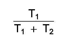
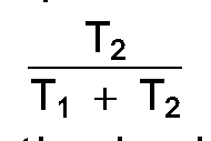
where T₁ and T₂ are identified in Figure 3, while the signal at a terminal 44 between
resistor 38 and capacitor 40 has a value portional to:
[0027] The difference in the signals at terminals 42 and 44 is proportional to:
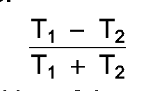
[0028] A change in position of the spoiler will change the relative resonance frequencies
of the two stationary tank circuits which, in turn, changes the repetition rates of
the output of pulse generator 22. This causes a corresponding change in the relative
values of T₁ and T₂ at the output of counter 19 and thereby changes the difference
in the signals at terminals 42 and 44.
[0029] Figures 4A, 4B and 4C show schematically three different types of tank circuits.
The tank circuits in Figure 4A represent the ones shown in Figure 2. A switch 46 represents
the action of the Figure 2 switching circuit in operatively connecting either stationary
inductance coil 12a or stationary inductance coil 12b to the pulse generator (not
shown) to form one or the other of the tank circuits with capacitor 16. Spoiler 14
also is shown in Figure 4A and its movement is represented by the double-ended arrow.
[0030] In Figure 4B, which shows an alternative tank circuit arrangement that can be used
in a modified embodiment of the invention, the tank circuits have a single stationary
inductance coil 48 which is connected to the pulse generator (not shown). In timed
alternating sequence, the switching means, represented by a switch 50, operatively
connect the two tank circuits formed by the two capacitors 52 and 54 and the coil
48 to the pulse generator.
[0031] In Figure 4C, the two tank circuits each have a stationary inductance coil 56 or
58 and a capacitor 60 or 62. The two tank circuits are operatively switched, in timed
alternating sequence, by the switching means, represented by a switch 64, to the pulse
generator (not shown).
[0032] It will be understood that the stationary inductance coils, shown as planar coils,
and the spoiler, shown as a planar solid member, may take different forms. For example,
the stationary inductance coils may be wound and the spoiler may be a planar coil.
[0033] The second embodiment of the present invention, shown in Figure 5, is generally similar
to the first embodiment, shown in Figure 2. Elements in Figure 5 corresponding to
elements in Figure 2 have been given the same reference numerals and will not be re-described.
[0034] In the Figure 5 circuit, the pulses from pulse generator 18 are supplied to the counter
portion 66 of a counter/timing circuit unit to develop a counter output signal such
as the one represented by waveform (D) of Figure 3. Waveform (E) of Figure 6 shows
two cycles of the counter output signal for two different positions of the sensor
spoiler.
[0035] The counter output signal is supplied to integrating means which develop an integration
signal, represented by waveform (F) in Figure 6, composed of a rising portion developed
during time T₁ from the positive-going first counter output pulse and a decaying portion
developed during time T₂ from the negative-going second counter output pulse. In its
simplest form, the integrating means include a resistor 67 and a capacitor 68. However,
for the embodiment of the present invention illustrated in Figure 5, the integrating
means also include a second resistor 69 to which an inverted version of the counter
output signal is supplied. This arrangement having a pair of integration circuits
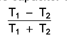
with a common capacitor, provides a differential output across capacitor 68 proportional
to:
[0036] Changes in the difference in the rates of the pulses from pulse generator 18 cause
changes in the relative values of T₁ and T₂. This, in turn, causes changes in the
difference in the signals across capacitor 68. Although the embodiment of the present
invention illustrated in Figure 5 has a capacitor which is multiplexed between two
resistors, two distinctly separate integrating circuits, each having a resistor and
a capacitor, may be used. Also, in its broadest application, the present invention
can include only one integrating circuit if differential operation is not needed.
Disposed between counter 66 and the integrating circuits are first switching means
for selectively connecting the counter to the integrating circuits. Such switching
means may include an electronic switch 70 which selectively couples the counter signal
to the integrating circuit composed of resistor 67 and capacitor 68 and an electronic
switch 71 which selectively couples the inverted version of the counter signal to
the integrating circuit composed of resistor 69 and capacitor 68.
[0037] Switches 70 and 71 are controlled by the timing circuit portion 72 of the counter/timing
circuit unit which supplies a first control signal along an output line 73 to switches
70 and 71 to disconnect counter 66 from the integrating circuit composed of resistor
67 and capacitor 68 and to disconnect counter 66 from the integrating circuit composed
of resistor 69 and capacitor 68. The first control signal supplied by timing circuit
72 is represented by waveform (G) in Figure 6 and is effective in interrupting development
of the integration signals. Waveform (H) represents the effect of the first control
signal from timing circuit 72 on the development of the integration signal developed
at the junction of resistor 67 and capacitor 68. An identical signal, but oppositely
directed to the one represented by waveform (H), is developed at the junction of resistor
69 and capacitor 68. So long as the first control signal is positive, switches 70
and 71 are closed and capacitor 68 functions in the usual way in charging and discharging
according to the signals supplied by counter 66. When the level of the first control
signal drops to zero, switches 70 and 71 open and the condition of capacitor 68 remains
unchanged while the switches remain open. The levels of the integration signals remain
at the levels at the start of the interruption. This is represented by the flat portions
of waveform (H). When switches 70 and 71 are again closed by the control signal, capacitor
68 resumes charging and discharging according to the signals supplied by counter 66.
[0038] The timing of the closing of switches 70 and 71 is selected at the mid-points of
the rise and decay portions of the integration signals to approximate the average
levels of the integration signals. As will become apparent, the durations of the closing
of switches 70 and 71 can be relatively short and shorter than illustrated in waveforms
(G) and (H). However, timing circuit 72 is simplified by making the open time of switches
70 and 71 equal to the closed times which precede and follow the open times, thereby
centering the interruptions of the development of the integration signal in the rising
and decaying portions of the integration signal.
[0039] A capacitor 73 serves to store the levels of the integration signals during periods
of interruption in the development of the integration signals. Disposed between capacitor
73 and the integrating circuits are second switching means for selectively connecting
the integrating circuits to this capacitor. Such switching means may include a pair
of electronic switches 74 and 75 which selectively transfer the level of the integration
signals to capacitor 73 during selected interruptions of the development of the integration
signals.
[0040] Switches 74 and 75 also are controlled by timing circuit 72 which supplies a second
control signal along an output line 76 to switches 74 and 75 to connect capacitor
73 to capacitor 68. The second control signal supplied by timing circuit 72 along
output line 76 is represented by waveform (I) in Figure 6. This signal is composed
of pulses which are present during selected open times of switches 70 and 71 during
the decay portions of the integration signal and sample the level of the integration
signal during these periods of interruption of the development of the integration
signal. In this way, the control signal supplied to switches 74 and 75 is effective
in transferring the level of the integration signal, as shown by the second flat portion
of each cycle of waveform (H), to capacitor 73.
[0041] Waveform (J) in Figure 6 represents the level of the integration signals transferred
to capacitor 73. By interrputing the development of the integration signals at the
mid points of the rise and decay times the levels of the integration signals during
the interruptions closely approximate the average value of the integration signals.
It will be understood that this result is produced whether the integrating means include
only one integration circuit or two integration circuits arranged to develop a differential
signal. The only difference between the two is the magnitude of the signals. If greater
accuracy is required, both the levels of interruption during the rise portions and
the levels of interruption during the decay portions can be sampled with the output
signal being developed by averaging the two.
[0042] For a more complete description of the circuitry for processing the output of pulse
generator 18 in Figure 5, reference is made to US-A-4709224.
[0043] Figure 7, which is a circuit diagram of a third preferred embodiment of the present
invention, illustrates that the present invention can be employed in sensing relative
movements within a moving assembly. One such application of the present invention
is sensing the twist imparted to a torqued rotating shaft.
[0044] The dashed lines in Figure 7 represent the placement of those components within the
dashed lines on a moving assembly, such as a steering column of an automobile. The
remaining components are on a stationary assembly which is mechanically isolated from
the moving assembly. U-A-637265 illustrates a sensor unit which can be employed in
the Figure 7 embodiment of the present invention. A pair of inductance coils 80 and
82 (Figure 7), can be carried, as shown in US-A-4637265, on a pair of angularly spaced
insulating boards. Twist imparted to a shaft to which the boards are secured is sensed
as a vane 84 (Figure 7), extending between the coils and secured to the shaft at a
different point, moves toward one coil and away from the other coil. Arrow 86 in Figure
7 represents the movement of vane 84 relative to coils 80 and 82. With coils 80 and
82 secured to the shaft at one axial location and vane 84 secured to the shaft at
a different axial location, the changes in position of the vane, relative to the positions
of the coils, correspond to the twist imparted to the shaft.
[0045] Inductance coils 80 and 82 and a capacitor 88 form a pair of tank circuits which
are operatively connected, in timed alternating sequence, through a pair of electronic
switches 90 and 92 controlled by a first logic and control circuit 93 to a first pulse
generator 94. The control of electronic switches 90 and 92 will be described shortly.
[0046] Pulse generator 92 produces pulses at a repetition rate corresponding to the resonance
frequency of the particular tank circuit connected to the input of the pulse generator.
The resonance frequencies of the two tank circuits are determined by the inductances
of the coils 80 and 82 which, in turn, are dependent upon the position of vane 84.
The combined effect of the two tank circuits and pulse generator 94 is generally similar
to the combined effect of the corresponding elements in the circuits of Figures 2
and 5, except that in the circuit of Figure 7 the switching between inductance coils
80 and 82 is separated by fixed periods of time during which power is transmitted
to the moving assembly.
[0047] It is important to establish, at the outset, that power for the components of the
moving assembly and control of electronic switches 90 and 92 is transmitted to the
moving assembly through a single transformer 96 having first and second windings 96a
and 96b, respectively, and information of the sensor position is transmitted from
the moving assembly also through transformer 96. This is accomplished by first transmitting
power to the moving assembly, next transmitting from the moving assembly information
of the position of vane 84 relative to coil 80, then transmitting power to the moving
assembly and finally transmitting from the moving assembly information of the position
of vane 84 relative to coil 82.
[0048] The foregoing sequence is initiated by a second logic and control circuit 98 which
turns on a second pulse generator 100 to produce a fixed rate series of pulses. A
counter 102 counts a prescribed number of these pulses and conditions logic and control
circuit 98 to supply a timing signal which controls transmission of power to the moving
assembly. Power is supplied by a first tri-state driver composed of three inverters
104, 106 and 108. Inverters 104 and 106 are controlled by the timing signal supplied
by logic and control circuit 98. The output from pulse generator 100 is supplied directly
to inverter 104 and through inverter 108 to inverter 106. Waveforms (K) and (L) of
Figure 8 represent the pulses supplied to inverters 104 and 106, respectively.
[0049] Waveform (M) of Figure 8 represents the timing signal supplied by logic and control
circuit 98. Timing signal pulse P₁ causes the tri-state driver to be connected to
winding 96b for the duration of pulse P₁. Waveform (N) of Figure 8 represents the
power transmitted to the moving assembly through transformer 96 and results from the
oppositely directed pulses produced by inverters 104 and 106 being supplied to opposite
ends of winding 96b. This power is supplied to an AM detector 110, connected across
winding 96a, and a peak detector 112 which together form a power supply and function
in the usual manner to develop a power supply voltage represented by terminal 114.
This power supply voltage operates electronic switches 90 and 92, logic and control
circuit 93, pulse generator 94, and an inverter 116. The actual connections between
terminal 114 and the units powered by the supply voltage at this terminal have been
omitted from Figure 7 for the sake of clarity.
[0050] The output of AM detector 110 also controls the operation of logic and control circuit
93. This is accomplished by detecting the timing signals which control the transmission
of power to the moving assembly. For the duration of the first timing signal pulse
P₁, logic and control circuit 93 inactivates electronic switches 90 and 92, so that
pulse generator 94 also is inactive and power can be transmitted from winding 96b
to 96a.
[0051] After the termination of timing signal pulse P₁, inverters 104 and 106 are inactivated,
so that the transmission of power is interrupted and the ends of winding 96b float.
This condition is detected by AM detector 110 and logic and control circuit 93 is
conditioned to close electronic switch 90 and thereby connect the tank circuit composed
of inductance coil 80 and capacitor 88 to the input of pulse generator 94. Pulses
having a repetition rate corresponding to the resonance frequency of this tank circuit
are transmitted from winding 96a through winding 96b to counter 102. After counter
102 has counted a prescribed number of pulses, it generates a counter output pulse
having a duration proportional to the time required to count the prescribed number
of pulses. This is represented by pulse T₁ of waveform (M) of Figure 8 which corresponds
to pulse T₁ of waveform (C) of Figure 3.
[0052] After the termination of pulse T₁, logic and control circuit 98 supplies a second
timing signal pulse P₂ which activates inverters 104 and 106 to transmit power to
the moving assembly. As with pulse P₁, pulse P₂ is detected by AM detector 110, so
that logic and control circuit 93 inactivates electronic switches 90 and 92 for the
duration of pulse P₂.
[0053] After the expiration of pulse P₂, logic and control circuit 93 closes electronic
switch 92, so that the tank circuit composed of inductance coil 82 and capacitor 88
is connected to the input of pulse generator 94. Pulse generator 94, responsive to
the second tank circuit, develops a second series of pulses having a repetition rate
corresponding to the resonance frequency of the second tank circuit. These pulses
are transmitted through transformer 96 to counter 102 which counts the prescribed
number of pulses and develops a second counter output pulse having a duration proportional
to the time required to count the prescribed number of pulses of the second series.
This is represented by pulse T₂ of waveform (M) of Figure 8 which corresponds to pulse
T₂ of waveform (C) of Figure 3 but is separated in time from pulse T₁ because of the
intervening transmission of power during pulse P₂.
[0054] Upon termination of the second counter output pulse T₂, logic and control circuit
98 activates inverters 104 and 106 to again transmit power to the moving assembly
and the cycle just described is repeated. It should be noted that the durations of
timing signal pulses P₁ and P₂ are different so that logic and control circuit 93
can distinguish between the two and thereby activate the appropriate electronic switch
90 or 92 associated with the tank circuit which is to be connected to pulse generator
94 following the particular power transmission.
[0055] The counter output pulses T₁ and T₂ are supplied from logic and control circuit 98
to a second tri-state driver composed of inverters 120 and 122 which are controlled
by the logic and control circuit to pass the first counter output pulses T₁ to a first
RC circuit, composed of a resistor 124 and a capacitor 126 and the second counter
output pulses T₂ to a second RC circuit composed of a resistor 128 and a capacitor
130. The difference in the signals at a pair of terminals 132 and 134 is proportional
to:
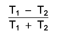
and represents the position of vane 84 relative to inductance coils 80 and 82.
[0056] The foregoing has set forth exemplary and preferred embodiments of the present invention.
It will be understood, however, that various alternatives will occur to those of ordinary
skill in the art without departure from the spirit or scope of the present invention
as claimed.
1. Sensor apparatus comprising an inductance coil sensor having first and second tank
circuits(12a, 12b, 16) and a movable metal member(14); means for moving said movable
metal member, relative to an inductance coil(48,56,58) of each of said first and second
tank circuits, in accordance with changes in a parameter being monitored, to change
the relative resonant frequencies of said first and second tank circuits; and circuit
means(18, 19, 20, 22, 32, 34, 36, 38, 40) responsive to changes in the relative resonant
frequencies of said first and second tank circuits, for developing indications of
changes in said parameter being monitored, said circuit means including a pulse generator(18)
for producing a first series of pulses having a repetition rate related to the resonant
frequency of said first tank circuit(12a, 16) and a second series of pulses having
a repetition rate related to the resonant frequency of said second tank circuit(12a,
16); a counter(19), responsive to said first and said second series of pulses, for
counting a prescribed number of pulses of said first series and the same number of
pulses of said second series and for developing a first counter output related to
the time required to count said prescribed number of pulses of the first series and
a second counter output related to the time required to count said prescribed number
of pulses of the second series; tank circuit switching means(20,22) responsive to
the completion of counting by the counter(19) of the prescribed number of pulses of
said first series for operatively connecting the second tank circuit(12b, 16) to the
pulse generator, and responsive to the completion of counting by the counter(19) of
the prescribed number of pulses of the second series for operatively connecting the
first tank circuit(12a, 16) to the counter(19) and means(34,36,32,38,40) to provide
an output representative of the difference between the frequencies of the pulses of
the first series and the pulses of the second series to indicate the position of the
movable member(14), the counter(19) being adapted to provide, as said first counter
output, an output pulse having a duration related to the time required to count said
prescribed number of pulses of the first series and also being adapted to provide,
as said second counter output, an output pulse having a duration related to the time
required to count said prescribed number of pulses of the second series, the tank
circuit(20,22) switching means being responsive to said counter output pulses, for
connecting the first tank circuit(12a, 16) to the pulse generator(18) for the duration
of the first counter output pulse, and for connecting the second tank circuit(l2b,
16) to the pulse generator(18) for the duration of the second counter output pulse,
the means(34,36,32,38,40) to provide an output, being responsive to said counter pulses
and providing an output indication of the relative time durations required for counting
the prescribed number of pulses of the first series, and the prescribed number of
pulses of the second series, characterised in that said means to provide an output
include integrating means(67,68,69), responsive to said counter output signal, for
developing an integration signal comprised of a rising portion developed from said
first counter output pulse and a decaying portion developed from said second counter
output pulse, said indicating means further including first switching means(70,71)
for selectively connecting said counter to said integrating means, a capacitor(73)
and second switching means(74,75) for selectively connecting said integrating means
to said capacitor; and said circuit means further include timing means(72) for supplying
a first control signal to said first switching means to disconnect said counter from
said integrating means and interrupt development of said integration signal, and for
supplying a second control signal to said second switching means to connect said integrating
means to said capacitor to transfer the level of said integration signal to said capacitor
during selected interruptions of the development of said integration signal.
2. Sensor apparatus comprising an inductance coil sensor having first and second tank
circuits(12a, 12b, 16) and a movable metal member(14); means for moving said movable
metal member, relative to an inductance coil(48,56,58) of each of said first and second
tank circuits, in accordance with changes in a parameter being monitored, to change
the relative resonant frequencies of said first and second tank circuits; and circuit
means(18, 19, 20, 22, 32, 34, 36, 38, 40) responsive to changes in the relative resonant
frequencies of said first and second tank circuits, for developing indications of
changes in said parameter being monitored, said circuit means including a pulse generator(18)
for producing a first series of pulses having a repetition rate related to the resonant
frequency of said first tank circuit(12a, 16) and a second series of pulses having
a repetition rate related to the resonant frequency of said second tank circuit(12a,
16); a counter(19), responsive to said first and said second series of pulses, for
counting a prescribed number of pulses of said first series and the same number of
pulses of said second series and for developing a first counter output related to
the time required to count said prescribed number of pulses of the first series and
a second counter output related to the time required to count said prescribed number
of pulses of the second series; tank circuit switching means(20,22) responsive to
the completion of counting by the counter(19) of the prescribed number of pulses of
said first series for operatively connecting the second tank circuit(12b, 16) to the
pulse generator, and responsive to the completion of counting by the counter(19) of
the prescribed number of pulses of the second series for operatively connecting the
first tank circuit(12a, 16) to the counter(19) and means(34,36,32,38,40) to provide
an output representative of the difference between the frequencies of the pulses of
the first series and the pulses of the second series to indicate the position of the
movable member(14), the counter(19) being adapted to provide, as said first counter
output, an output pulse having a duration related to the time required to count said
prescribed number of pulses of the first series and also being adapted to provide,
as said second counter output, an output pulse having a duration related to the time
required to count said prescribed number of pulses of the second series, the tank
circuit(20,22) switching means being responsive to said counter output pulses, for
connecting the first tank circuit(12a, 16) to the pulse generator(l8) for the duration
of the first counter output pulse, and for connecting the second tank circuit(l2b,
16) to the pulse generator(18) for the duration of the second counter output pulse,
the means(34,36,32,38,40) to provide an output, being responsive to said counter pulses
and providing an output indication of the relative time durations required for counting
the prescribed number of pulses of the first series, and the prescribed number of
pulses of the second series, characterised in that said counter(66) includes means
for supplying an inverted version of said counter output signal; said means to provide
an output include a first integration circuit(67,68) responsive to said counter output
signal for developing a first integration signal composed of a rising portion developed
from said first counter output pulse and a decaying portion developed from said second
counter output pulse, a second integration circuit(69,68), responsive to said inverted
version of said counter output signal, for developing a second integration signal
comprised of a decaying portion from an inverted version of said first counter output
pulse and a rising portion from an inverted version of said second counter output
pulse, first switching means(70,71) for selectively connecting said counter to said
first and second integration circuits, a capacitor(73) and second switching means(74,75)
for selectively connecting said first and said integration circuits to said capacitor(73);
and said circuit means further include timing means(72) for supplying a first control
signal to said first switching means(70,71) to disconnect said counter(66) from said
first and said second integration circuits(67,68,69) and interrupt development of
said integration signals, and a second control signal to said second switching means(74,75)
to connect said first and said second integration circuits(67,68,69) to said capacitor(73)
to transfer the levels of said integration signals to said capacitor during selected
interruptions of the development of said integration signals.
3. Sensor apparatus according to Claim 1 or 2, wherein said first and second tank circuits
have a single capacitor(16) which is connected to said pulse generator(18) and first
and second inductance coils(12a, 12b) the coils being operatively connected to the
capacitor(16) in time alternating sequence, to form said first(12a,16) and said second(12b,16)
tank circuits, by the tank circuit switching means(20,22).
4. Sensor apparatus according to Claim 1 or 2, wherein said first and said second tank
circuits have a single inductance coil(48) which is connected to said pulse generator(18)
and first and second capacitors(52,54), the capacitors being operatively connected
to the coil(48), in timed alternating sequence, to form said first(52,48) and said
second(54,48) tank circuits , by the tank circuit switching means(20,22).
5. Sensor apparatus according to Claim 1 or 2, wherein said first and said second tank
circuits(56,60,58,62) each have an inductance coil(56,58) and capacitor(60,62) and
said first and said second tank circuits are operatively connected, in timed alternating
sequence, to said pulse generator by the tank circuit switching means(20,22).
6. Sensor apparatus according to Claim 1 or any Claim dependent thereon, wherein in use,
the development of said integration signal is interrupted at the mid-point of said
rising and decaying portions.
7. Sensor apparatus according to Claim 1 or any one of Claims 3 to 5 wherein said counter(66)
includes means for supplying an inverted version of said counter output signal; said
means to provide an output include a first integration circuit(67,68) responsive to
said counter output signal for developing a first integration signal composed of a
rising portion developed from said first counter output pulse and a decaying portion
developed from said second counter output pulse, a second integration circuit(69,68),
responsive to said inverted version of said counter output signal, for developing
a second integration signal comprised of a decaying portion from an inverted version
of said first counter output pulse and a rising portion from an inverted version of
said second counter output pulse, first switching means(70,71) for selectively connecting
said counter to said first and second integration circuits, a capacitor(73) and second
switching means(74,75) for selectively connecting said first and said integration
circuits to said capacitor(73); and said circuit means further include timing means(72)
for supplying a first control signal to said first switching means(70,71) to disconnect
said counter(66) from said first and said second integration circuits(67,68,69) and
interrupt development of said integration signals, and a second control signal to
said second switching means(74,75) to connect said first and said second integration
circuits(67,68,69) to said capacitor(73) to transfer the levels of said integration
signals to said capacitor during selected interruptions of the development of said
integration signals.
8. Sensor apparatus according to Claim 2 or any Claim dependent thereon wherein, in use,
the development of said integration signals is interrupted at the mid-points of said
rising and decaying portions.
9. Sensor apparatus according to any one of the preceding Claims, wherein said tank circuit
switching means(90,92) are responsive to said first and second counter output pulses
and include control means(93) for delaying connecting said first and second tank circuits
to said pulse generator(94) for fixed periods of time following the terminations of
said first and said second counter output pulses.
10. Sensor apparatus according to Claim 9, wherein said fixed periods of time following
said termination of said first and second counter output pulses are different.
1. Sensorgerät mit einem Induktionsspulensor, der mit ersten und zweiten Schwingkreisen
(12a, 12b, 16) und einem beweglichen Metallteil (14) versehen ist; Mitteln zum Bewegen
des beweglichen Metallteils relativ zu einer Induktionsspule (48, 56, 58) des ersten
und des zweiten Schwingkreises in Übereinstimmung mit Änderungen eines beobachteten
Parameters zur Änderung der jeweiligen Resonanzfrequenzen des ersten bzw. des zweiten
Schwingkreises; und Schaltmitteln (19, 20, 22, 32, 34, 36, 38, 40), die auf Änderungen
der jeweiligen Resonanzfrequenzen des ersten bzw. zweiten Schwingkreises zur Entwicklung
von Angaben der Änderungen in den beobachteten Paramentern ansprechen, wobei die Schaltmittel
einen Impulsgenerator (18) zum Erzeugen einer ersten Serie von Impulsen mit einer
der Resonanzfrequenz des ersten Schwingkreises (12a, 16) entsprechenden Wiederholungsrate
und einer zweiten Serie von Impulsen mit einer der Resonanzfrequenz des zweiten Schwingkreises
(12a, 16) entsprechenden Wiederholungsrate, einen Zähler (19), der auf die erste Serie
von Impulsen anspricht zum Zählen einer vorgegebenen Anzahl von Impulsen der erstern
Serie und derselben Anzahl von Impulsen der zweiten Serie und zum Entwickeln eines
ersten Zählerausgangssignals, das der Zeit entspricht, die zum Zählen der vorgegebenen
Anzahl von Impulsen der ersten Serie erforderlich ist, und eines zweiten Zählerausgangsignals,
das der Zeit entspricht, die erforderlich ist, um die vorgegebene Anzahl von Impulsen
der zweiten Serie zu zählen; Schwingkreisumschaltmittel (20, 22), die auf das Zählen
der vorgegebenen Anzahl von Impulsen der ersten Serie durch den Zähler (19) zur betriebsmäßigen
Verbindung des zweiten Schwingreises (12b, 16) mit dem Impulsgenerator ansprechen
und auf die Beendigung des Zählens der vorgegebenen Anzahl von Impulsen der zweiten
Serie durch den Zähler (19) zum betriebsmäßigen Verbinden des ersten Schaltkreises
(12a, 16) mit dem Zähler (19) ansprechen und Mittel (34, 36, 32, 38, 40) zum Schaffen
eines Ausgangssignals, das die Differenz zwischen den Frequenzen der Impulse der ersten
Serie und der Impulse der zweiten Serie entspricht, um die Position des beweglichen
Elements (14) anzugeben, aufweisen, wobei der Zähler (19) dazu eingerichtet ist, als
erstes Ausgangssignal einen Ausgangsimpuls zu schaffen, dessen Dauer der Zeit entspricht,
die benötigt wird, um die vorgegebene Anzahl von Impulsen der ersten Serie zu zählen
und weiter dazu eingerichtet ist, als zweites Zählerausgangssignal einen Ausgangsimpuls
zu schaffen, der eine Dauer hat, die der Zeit entspricht, die erforderlich ist, um
die vorgegebene Anzahl von Impulsen der zweiten Serie zu zählen, wobei das Umschaltmittel
für die Schwingkreise (20, 22) auf die Zählerausgangsimpulse zum Verbinden des ersten
Schwingkreises (12a, 16) mit dem Impulsgenerator (18) für die Dauer des ersten Zählerausgangsimpulses
und zum Verbinden des zweiten Schwingkreises (12b, 16) mit dem Impulsgenerator (18)
für die Dauer der zweiten Zählerausgangssignalimpulse anspricht, wobei die Mittel
(34, 36, 32, 38, 40) zum Erzeugen eines Ausgangssignals auf die Zählerimpulse ansprechen
und ein Ausgangssignal schaffen, das den jeweiligen Zeitdauern angibt, die zum Zählen
einer vorgegebenen Anzahl von Impulsen der ersten Serie und der vorgegebenen Anzahl
von Impulsen der zweiten Serie erforderlich ist, dadurch gekennzeichnet, daß die Mittel
zum Schaffen eines Ausgangssignals Integrationsmittel (67, 68, 69) aufweisen, die
auf ein Zählerausgangssignal zum Entwickeln eines Integrationssignals ansprechen,
das aus einem ansteigenden Abschnitt, welches von dem ersten Zählerausgangsimpuls
erzeugt wird und einem abfallenden Abschnitt, der von dem zweiten Zählerausgangsimpuls
entwickelt wird, besteht, wobei die Anzeigemittel weiter erste Umschaltmittel (70,
71) zum wahlweisen Verbinden des Zählers mit dem Integrationsmittel, einen Kondensator
(73) und zweite Umschaltmittel (74, 75) zum wahlweisen Verbinden der Integrationsmittel
mit der Kapazität aufweisen, und die Schaltmittel weiter Zeitgeber (72) zum Anlegen
eines ersten Steuersignals an das erste Umschaltmittel zum Lösen der Verbindung des
Zählers von dem Integrationsmittel und zum Unterbrechen der Entwicklung des Integrationssignals
und zum Anlegen eines zweiten Steuersignals an das zweite Umschaltmittel zum Verbinden
der Integrationsmittel mit der Kapazität zum Übertragen des Pegels des Integrationssignals
auf die Kapazität während ausgewählter Unterbrechungen der Entwicklung des Integrationssignals,
aufweisen.
2. Sensorgerät mit einem Induktionsspulensensor, der mit ersten und zweiten Schwingkreisen
(12a, 12b, 16) und einem beweglichen Metallteil (14) versehen ist; Mitteln zum Bewegen
des beweglichen Metallteils relativ zu einer Induktionsspule (48, 56, 58) des ersten
und des zweiten Schwingkreises in Übereinstimmung mit Änderungen eines beobachteten
Parameters zur Änderung der jeweiligen Resonanzfrequenzen des ersten bzw. des zweiten
Schwingkreises; und Schaltmitteln (19, 20, 22, 32, 34, 36, 38, 40), die auf Änderungen
der jeweiligen Resonanzfrequenzen des ersten bzw. zweiten Schwingkreises zur Entwicklung
von Angaben der Änderungen in den beobachteten Paramentern anspricht, wobei die Schaltmittel
einen Impulsgenerator (18) zum Erzeugen einer ersten Serie von Pulsen mit einer der
Resonanzfrequenz des ersten Schwingkreises (12a, 16) entsprechenden Wiederholungsrate
und einer zweiten Serie von Impulsen mit einer der Resonanzfrequenz des zweiten Schwingkreises
(12a, 16) entsprechenden Wiederholungsrate aufweisen; einem Zähler (19), der auf die
erste Serie von Impulsen zum Zählen einer vorgegebenen Anzahl von Impulsen der ersten
Serie und derselben Anzahl von Impulsen der zweiten Serie und zum Entwickeln eines
ersten Zählerausgangssignals, das der Zeit entspricht, die zum Zählen der vorgegebenen
Anzahl von Impulsen der ersten Serie erforderlich ist, und eines zweiten Zählerausgangssignals,
das der Zeit entspricht, die erforderlich ist, um die vorgegebene Anzahl von Impulsen
der zweiten Serie zu zählen, anspricht; Schwingkreisumschaltmitteln (20, 22), die
auf das Zählen der vorgegebenen Anzahl von Impulsen der ersten Serie durch den Zähler
(19) zur betriebsmäßigen Verbindung des zweiten Schwingreises (12b, 16) mit dem Impulsgenerator
und auf die Beendigung des Zählens der vorgegebenen Anzahl von Impulsen der zweiten
Serie durch den Zähler (19) zum betriebsmäßigen verbinden des ersten Schaltkreises
(12a, 16) mit dem Zähler (19) ansprechen und Mitteln (34, 36, 32, 38, 40) zum Schaffen
eines Ausgangssignals, das der Differenz zwischen den Frequenzen der Impulse der ersten
Serie und der Impulse der zweiten Serie entspricht, um die Position des beweglichen
Elements (14) anzugeben, wobei der Zähler (19) dazu eingerichtet ist, als erstes Ausgangssignal
einen Ausgangsimpuls zu schaffen, dessen Dauer der Zeit entspricht, die benötigt wird,
um die vorgegebene Anzahl von Impulsen der ersten Serie zu zählen und weiter dazu
eingerichtet ist, als zweites Zählerausgangssignal einen Ausgangsimpuls zu schaffen,
der eine Dauer hat, die der Zeit entspricht, die erforderlich ist, um die vorgegebene
Anzahl von Impulsen der zweiten Serie zu zählen, wobei das Umschaltmittel für die
Schwingkreise (20, 22) auf die Zählerausgangsimpulse zum Verbinden des ersten Schwingkreises
(12a, 16) mit dem Impulsgenerator (18) für die Dauer der ersten Zählerausgangsimpulses
und zum Verbinden des zweiten Schwingkreises (12b, 16) mit dem Impulsgenerator (18)
für die Dauer der zweiten Zählerausgangssignalimpulse anspricht, wobei die Mittel
(34, 36, 32, 38, 40) zum Erzeugen eines Ausgangssignals auf die Zählerimpulse ansprechen
und ein Ausgangssignal schaffen, das die jeweiligen Zeitdauern angibt, die zum Zählen
einer vorgegebenen Anzahl von Impulsen der ersten Serie und der vorgegebenen Anzahl
von Impulsen der zweiten Serie erforderlich ist, dadurch gekennzeichnet, daß der Zähler
(66) Mittel zum Bilden einer invertierten Version des Zählerausgangssignals aufweist,
wobei die Mittel zum Schaffen eines Ausgangssignals einen ersten Integrationsschaltkreis
(67, 68), der auf das Zählerausgangssignal zur Entwicklung eines ersten Integrationssignals
anspricht, das aus einem ansteigenden Abschnitt, der von dem ersten Zählerausgangsimpuls
erzeugt wird und einem abfallenden Abschnitt, der von dem zweiten Zählerausgangsimpuls
erzeugt wird, einen zweiten Integrationsschaltkreis (69, 68), der auf die invertierte
Version des Zählerausgangssignals anspricht, um ein zweites Integrationssignal zu
entwickeln, das aus einem abfallenden Abschnitt einer invertierten Version des ersten
Zählerausgangsimpulses anspricht und einem ansteigenden Abschnitt von einer invertierten
Version des zweiten Zählerausgangsimpulses besteht, erste Schaltmittel (70, 71) zum
wahlweisen Verbinden des Zählers mit dem ersten und dem zweiten Integrationsschaltkreis,
einen Kondensator (73) und zweite Schaltmittel (74, 75) zum wahlweisen Verbinden des
ersten und des zweiten Integrationsschaltkreises mit dem Kondensator (73) aufweist;
und wobei die Schaltmittel weiter Zeitgebermittel (72) zum Versorgen des ersten Schaltmittels
(70, 71) mit einem ersten Steuersignal zum Trennen des Zählers (66) von dem ersten
und dem zweiten Integrationsschaltkreis (67, 68, 69) und zum Unterbrechen der Entwicklung
der Integrationssignale, und zum Anlegen eines zweiten Steuersignals an die zweiten
Schaltmittel (74, 75) und zum Verbinden des ersten und des zweiten Integrationsschaltkreises
(67, 68, 69) mit dem Kondensator (73) zum Übertragen der Pegel der Integrationssignale
an den Kondensator während ausgewählter Unterbrechungen der Entwicklung der Integrationssignale
aufweisen.
3. Sensorgerät nach Anspruch 1 oder 2, wobei die ersten und zweiten Schaltkreise einen
einzigen Kondensator (16), der mit dem Impulsgenerator (18) verbunden ist, und erste
und zweite Induktivitätsspulen (12a, 12b), die betreibsimäßig mit dem Kondensator
(16) in wechselnder Abfolge verbunden sind, aufweist, um durch die Schwingkreisumschalmittel
(20, 22) den ersten (12a, 16) und den zweiten (12b, 16) Schwingkreis zu bilden.
4. Sensorgerät nach Anspruch 1 oder 2, wobei der erste und der zweite Schwingkreis eine
einzige Induktlonsspule (48), die mit dem Impulsgenerator (18) verbunden ist, und
erste und zweite Kondensatoren (52, 54), die durch die Schwingkreisumschaltmittel
(20, 22) betriebsmäßig zeitlich alternierend zur Bildung des ersten (52, 48) und des
zweiten (54, 48) Schwingkreises mit der Spule (48) verbunden sind, aufweisen.
5. Sensorgerät nach Anspruch 1 oder 2, wobei die ersten und die zweiten Schwingkreise
(56, 60, 58, 62) jeweils eine Induktionsspule (56, 58) und einen Kondensator (60,
62) aufweisen und der erste und der zweite Schwingkreis betriebsmäßig in zeitlich
alternierender Abfolge durch die Schwingkreisumschaltmittel (20, 22) mit dem Impulsgenerator
Verbunden sind.
6. Sensorgerät nach Anspruch 1 oder einem von diesem abhängigen Anspruch, wobei bei der
Verwendung die Entwicklung des Integrationssignals an dem Mittelpunkt des ansteigenden
und des abfallenden Abschnitts unterbrochen wird.
7. Sensorgerät nach Anspruch 1 oder einem der Ansprüche 3 bis 5, wobei der Zähler (66)
Mittel zum Erzeugen einer invertierten Version des Zählerausgangssignals aufweist,
wobei die Mittel zum Bilden eines Ausgangssignals einen ersten Integrationsschaltkreis
(67, 68), der auf das Zählerausgangssignal zur Entwicklung eines ersten Integrationssignals,
das aus einem von dem ersten Zählerausgangssignal entwickelten ansteigenden Abschnitt
und einem von dem zweiten Zählerausgangsimpuls entwickelten absteigenden Abschnitt
besteht, anspricht, einen zweiten Integrationsschaltkreis (69, 68), der auf die invertierte
Version des Zählerausgangssignals zur Entwicklung eines zweiten aus einem absteigenden
Abschnitt aus der invertierten Version des ersten Zählerausgangsimpulses und einem
absteigenden Abschnitt aus einer invertierten Version des zweiten Zählerausgangsimpulses
besteht, anspricht, erste Schaltmittel (71) zum selektiven Verbinden des Zählers mit
dem ersten und dem zweiten Integrationsschaltkreis, einen Kondensator (73) und Zweite
Schaltmitteln (74, 75) zum wahlweisen Verbinden des ersten und des zweiten Integrationsschaltkreises
mit dem Kondensator (73) aufweisen; und wobei das Schaltmittel weiter Zeitgebermittel
(72) zum zum Schaffen eines ersten Steuersignals für das erste Schaltmittel (70, 71)
zum Trennen des Zählers (66) von dem ersten und dem Integrationsschaltkreis (67, 68,
69) und zum Unterbrechen der Entwicklung der Integrationssignale und ein zweites Steuersignal
an das zweite Schaltmittel (74, 75) zum Trennen des ersten und des zweiten Integrationsschaltkreises
zum Trennen des ersten und des zweiten Integrationsschaltkreises (67, 68, 69) von
dem Kondensator (73) zum Übertragen der Pegel der Integrationssignale zu dem Kondensator
während ausgewählter Unterbrechungen der Entwicklung der Integrationssignale aufweist.
8. Sensorgerät nach Anspruch 2 oder einem der von diesem abhängigen Ansprüche, wobei
bei Verwendung die Entwicklung der Integrationssignale an den Mittelpunkten der absteigenden
Abschnitte unterbrochen wird.
9. Sensorgerät nach einem der vorangehenden Ansprüche, wobei die Schwingkreisumschaltmittel
(90, 92) auf die ersten und die zweiten Zählerausgangsimpulse ansprechen und steuermittel
(93) zur Verzögerung der Verbindung des ersten Schwingkreises und des zweiten Schwingkreises
mit dem Impulsgenerator (94) für feste Zeitdauern, die dem Ende der ersten und zweiten
Zählerausgangsimpulse folgen, aufweisen.
10. Sensorgerät nach Anspruch 9 wobei die festen Zeitdauern, die dem Ende der ersten und
der zweiten Zählerausgangsimpulse folgen, unterschiedlich sind.
1. Dispositif capteur comprenant un capteur à bobine d'inductance possédant des premier
et second circuits bouchons résonnants (12a, 12b, 16) et un élément métallique mobile
(14) ; un moyen pour déplacer ledit élément métallique mobile par rapport à une bobine
d'inductance (48, 56, 58) de chacun desdits premier et second circuits résonnants,
en conformité avec des changements d'un paramètre surveillé, afin de changer les fréquences
de résonnance relatives desdits premier et second circuits résonnants ; et une circuiterie
(18, 19, 20, 22, 32, 34, 36, 38, 40) sensible a des changements des fréquences de
résonnance relatives desdits premier et second circuits résonnants pour produire des
indications de changements dudit paramètre surveillé, ladite circuiterie comportant
un générateur d'impulsions (18) pour générer une première série d'impulsions ayant
un taux de répétition en rapport avec la fréquence de résonnance dudit premier circuit
résonnant, (12a, 16) et une seconde série d'impulsions ayant un taux de répétition
en rapport avec la fréquence de résonnance dudit second circuit résonnant (12a, 16)
; un compteur (19) sensible auxdites première et seconde séries d'impulsions pour
compter un nombre prescrit d'impulsions de ladite première série et le même nombre
d'impulsions de ladite seconde série et pour élaborer un premier signal de sortie
de compteur en rapport avec le temps nécessaire au comptage dudit nombre prescrit
d'impulsions de la première série et un second signal de sortie de compteur en rapport
avec le temps nécessaire au comptage dudit nombre prescrit d'impulsions de la seconde
série ; des moyens de commutation de circuit résonnant (20, 22) sensibles à la fin
du comptage par le compteur (19) du nombre prescrit d'impulsions de ladite première
série pour connecter fonctionnellement le second circuit résonnant (12b, 16) au générateur
d'impulsions, et sensible à la fin du comptage par le compteur (19) du nombre prescrit
d'impulsions de la seconde série pour connecter fonctionnellement le premier circuit
résonnant (12a, 16) au compteur (19) et des moyens (34, 36, 32, 38, 40) pour fournir
un signal de sortie représentatif de la différence entre les fréquences des impulsions
de la première série et les impulsions de la seconde série afin d'indiquer la position
de l'élément mobile (14), le compteur (19) étant adapté pour fournir, en tant que
premier signal de sortie de compteur, une impulsion de sortie dont la durée est en
rapport avec le temps nécessaire au comptage dudit nombre prescrit d'impulsions de
la première série, et également adapté pour fournir, en tant que second signal de
sortie du compteur, une impulsion de sortie dont la durée est en rapport avec le temps
nécessaire au comptage dudit nombre prescrit d'impulsions de la seconde série, les
moyens de commutation de circuit résonnant (20, 22) étant sensibles auxdites impulsions
de sortie de compteur, pour connecter le premier circuit résonnant (12a, 16) au générateur
d'impulsions (18) pendant la durée de la première impulsion de sortie du compteur
et pour connecter le second circuit résonnant (12b, 16) au générateur d'impulsions
(18) pendant la durée de la seconde impulsion de sortie du compteur, les moyens (34,
36, 32, 38, 40) destinés à fournir un signal de sortie étant sensibles auxdites impulsions
du compteur et fournissant une indication de sortie des durées relatives nécessaires
au comptage du nombre prescrit d'impulsions de la première série et du nombre prescrit
d'impulsions de la seconde série, caractérisé en ce que lesdits moyens destinés à
fournir un signal de sortie comportent un moyen d'intégration (67, 68, 69) sensible
audit signal de sortie du compteur, pour élaborer un signal d'intégration comprenant
une partie montante formée à partir de ladite première impulsion de sortie du compteur
et une partie descendante formée à partir de ladite seconde impulsion de sortie du
compteur, lesdits moyens d'indication comportant en outre un premier moyen de commutation
(70, 71) pour connecter ledit compteur sélectivement audit moyen d'intégration, un
condensateur (73) et un second moyen de commutation (74, 75) pour connecter ledit
moyen d'intégration sélectivement audit condensateur ; et en ce que ladite circuiterie
comporte en outre un moyen de synchronisation (72) pour délivrer un premier signal
de commande audit premier moyen de commutation afin de déconnecter ledit compteur
dudit moyen d'intégration et d'interrompre l'élaboration dudit signal d'intégration,
et pour délivrer un second signal de commande audit second moyen de commutation afin
de connecter ledit moyen d'intégration audit condensateur dans le but de transférer
le niveau dudit signal d'intégration audit condensateur pendant des interruptions
sélectionnées de l'élaboration dudit signal d'integration.
2. Dispositif capteur comprenant un capteur a bobine d'inductance possédant des premier
et second circuits bouchons résonnants (12a, 12b, 16) et un élément métallique mobile
(14); un moyen pour déplacer ledit élément métallique mobile par rapport à une bobine
d'inductance (48, 56, 58) de chacun desdits premier et second circuits résonnants,
en conformité avec des changements d'un paramètre surveillé, afin de changer les fréquences
de résonance relatives desdits premier et second circuits résonnants ; et une circuiterie
(18, 19, 20, 22, 32, 34, 36, 38, 40) sensible à des changements des fréquences de
resonance relatives desdits premier et second circuits résonnants pour produire des
indications de changements du paramètre surveillé, ladite circuiterie comportant un
générateur d'impulsions (18) pour générer une première série d'impulsions ayant un
taux de répétition en rapport avec la fréquence de résonance dudit premier circuit
résonnant (12a, 16) et une seconde série d'impulsions ayant un taux de répétition
en rapport avec la fréquence de résonance dudit second circuit résonnant (12a, 16)
; un compteur (19) sensible auxdites première et seconde séries d'impulsions pour
compter un nombre prescrit d'impulsions de ladite première série et le même nombre
d'impulsions de ladite seconde série et pour élaborer un premier signal de sortie
de compteur en rapport avec le temps nécessaire au comptage dudit nombre prescrit
d'impulsions de la première série et un second signal de sortie de compteur en rapport
avec le temps nécessaire au comptage dudit nombre prescrit d'impulsions de la seconde
série ; des moyens de commutation de circuit résonnant (20, 22) sensibles à la fin
du comptage par le compteur (19) du nombre prescrit d'impulsions de ladite première
série pour connecter fonctionnellement le second circuit résonnant (12b, 16) au générateur
d'impulsions, et sensible a la fin du comptage par le compteur (19) du nombre prescrit
d'impulsions de la seconde série pour connecter fonctionnellement le premier circuit
résonnant (12a, 16) au compteur (19), et des moyens (34, 36, 32, 38, 40) pour fournir
un signal de sortie représentatif de la différence entre les fréquences des impulsions
de la première série et les impulsions de la seconde série afin d'indiquer la position
de l'élément mobile (14), le compteur (19) étant adapté pour fournir, en tant que
premier signal de sortie de compteur, une impulsion de sortie dont la durée est en
rapport avec le temps nécessaire au comptage dudit nombre prescrit d'impulsions de
la première série, et également adapté pour fournir, en tant que second signal de
sortie du compteur, une impulsion de sortie dont la durée est en rapport avec le temps
nécessaire au comptage dudit nombre prescrit d'impulsions de la seconde série, les
moyens de commutation de circuit résonnant (20, 22) étant sensibles auxdites impulsions
de sortie de compteur, pour connecter le premier circuit résonnant (12a, 16) au générateur
d'impulsions (18) pendant la durée de la première impulsion de sortie du compteur
et pour connecter le second circuit résonnant (12b, 16) au générateur d'impulsions
(18) pendant la durée de la seconde impulsion de sortie du compteur, les moyens (34,
36, 32, 38, 40) destinés à fournir un signal de sortie étant sensibles auxdites impulsions
du compteur et fournissant une indication de sortie des durées relatives nécessaires
au comptage du nombre prescrit d'impulsions de la première série et du nombre prescrit
d'impulsions de la seconde série, caractérisé en ce que ledit compteur (66) comporte
des moyens pour délivrer une version inversée dudit signal de sortie de compteur ;
en ce que lesdits moyens destinés à fournir un signal de sortie comportent un premier
circuit d'intégration (67, 68) sensible audit signal de sortie du compteur pour élaborer
un premier signal d'intégration composé d'une partie montante formée à partir de ladite
première impulsion de sortie du compteur, et d'une partie descendante formée à partir
de ladite seconde impulsion de sortie du compteur, un second circuit d'intégration
(69, 68) sensible à ladite version inversée dudit signal de sortie du compteur pour
élaborer un second signal d'intégration comprenant une partie descendante formée à
partir d'une version inversée de ladite première impulsion de sortie du compteur,
et une partie montante formée à partir d'une version inversée de ladite seconde impulsion
de sortie du compteur, un premier moyen de commutation (70, 71) pour connecter ledit
compteur sélectivement auxdits premier et sesond circuits d'intégration, un condensateur
(73) et un second moyen de commutation (74, 75) pour connecter lesdits premier et
second circuits d'intégration sélectivement audit condensateur (73) ; et en ce que
ladite circuiterie comporte en outre un moyen de synchronisation (72) pour délivrer
un premier signal de commande audit premier moyen de commutation (70, 71) afin de
déconnecter ledit compteur (66) desdits premier et second circuits d'intégration (67,
68, 69) et d'interrompre l'élaboration desdits signaux d'integration, et un second
signal de commande audit second moyen de commutation (74, 75) afin de connecter lesdits
premier et second circuits d'intégration (67, 68, 69) audit condensateur (73) dans
le but de tranférer les niveaux desdits signaux d'intégration audit condensateur pendant
des interruptions sélectionnées de l'élaboration desdits signaux d'intégration.
3. Dispositif capteur selon la revendication 1 ou 2 dans lequel lesdits premier et second
circuits résonnants possèdent un seul condensateur (16) qui est connecté audit générateur
d'impulsions (18) et des première et seconde bobines d'inductance (12a, 12b) bobines
qui sont connectées fonctionnellement au condensateur (16), suivant une séquence alternante
synchronisée, afin de former lesdits premier (12a, 16) et second (12b, 16) circuits
résonnants, par les moyens de commutation de circuit résonnant (20, 22).
4. Dispositif capteur selon la revendication 1 ou 2, dans lequel lesdits premier et second
circuits résonnants possèdent une seule bobine d'inductance (48) qui est connectée
audit générateur d'impulsions (18) et des premier et second condensateurs (52, 54),
condensateurs qui sont connectés fonctionnellement à la bobine (48), suivant une séquence
alternante synchronisée, pour former lesdits premier (52, 48) et second (54, 48) circuits
résonnants, par les moyens de commutation de circuit résonnant (20, 22).
5. Dispositif capteur selon la revendication 1 ou 2, dans lequel lesdits premier et second
circuits résonnants (56, 60, 58, 52) possèdent chacun une bobine d'inductance (56,
58) et un condensateur (60, 62), lesdits premier et second circuits résonnants étant
connectés fonctionnellement, suivant une séquence alternante synchronisée, audit générateur
d'impulsions par les moyens de commutation de circuit résonnant (20, 22).
6. Dispositif capteur selon la revendication 1 ou l'une quelconque des revendications
dépendantes de celle-ci, dans lequel, en service, l'élaboration dudit signal d'intégration
est interrompue au point central desdites parties montante et descendante.
7. Dispositif capteur selon la revendication 1 ou l'une quelconque des revendications
3 à 5, dans lequel ledit compteur (66) comporte des moyens pour délivrer une version
inversée dudit signal de sortie de compteur ; lesdits moyens destinés à fournir un
signal de sortie comportent un premier circuit d'intégration (67, 68) sensible audit
signal de sortie du compteur pour élaborer un premier signal d'intégration composé
d'une partie montante formée à partir de ladite première impulsion de sortie du compteur,
et d'une partie descendante formée à partir de ladite seconde impulsion de sortie
du compteur, un second circuit d'intégration (69, 68) sensible à ladite version inversée
dudit signal de sortie du compteur pour élaborer un second signal d'intégration comprenant
une partie descendante formée à partir d'une version inversée de ladite première impulsion
de sortie du compteur, et une partie montante formée à partir d'une version inversée
de ladite seconde impulsion de sortie du compteur, un premier moyen de commutation
(70, 71) pour connecter ledit compteur sélectivement auxdits premier et second circuits
d'intégration, un condensateur (73) et un second moyen de commutation (74, 75) pour
connecter lesdits premier et second circuits d'intégration sélectivement audit condensateur
(73) ; et ladite circuiterie comporte en outre un moyen de synchronisation (72) pour
délivrer un premier signal de commande audit premier moyen de commutation (70, 71)
afin de déconnecter ledit compteur (66) desdits premier et second circuits d'intégration
(67, 68, 69) et d'interrompre l'élaboration desdits signaux d'intégration, et un second
signal de commande audit second moyen de commutation (74, 75) afin de connecter lesdits
premier et second circuits d'intégration (67, 68, 69) audit condensateur (73) dans
le but de transférer les niveaux desdits signaux d'intégration audit condensateur
pendant des interruptions sélectionnées de l'élaboration desdits signaux d'intégration.
8. Dispositif capteur selon la revendication 2 ou l'une quelconque des revendications
dépendantes de celle-ci, dans lequel, en service, l'élaboration desdits signaux d'intégration
est interrompue aux points centraux desdites parties montantes et descendantes.
9. Dispositif capteur selon l'une quelconque des revendications précédentes, dans lequel
lesdits moyens de commutation de circuit résonnant (90, 92) sont sensibles auxdites
première et seconde impulsions de sortie du compteur et comportent un moyen de commande
(93) pour retarder la connexion desdits premier et second circuits résonnants audit
générateur d'impulsions (94) pendant des périodes de temps fixes après la fin desdites
première et seconde impulsions de sortie du compteur.
10. Dispositif capteur selon la revendication 9, dans lequel lesdites périodes de temps
fixes après la fin desdites première et seconde impulsions de sortie du compteur sont
différentes.