| (19) |
 |
|
(11) |
EP 0 216 197 B1 |
| (12) |
EUROPEAN PATENT SPECIFICATION |
| (45) |
Mention of the grant of the patent: |
|
18.10.1989 Bulletin 1989/42 |
| (22) |
Date of filing: 29.08.1986 |
|
| (51) |
International Patent Classification (IPC)4: B24B 7/18 |
|
| (54) |
Milling or grinding machine for finishing flat surfaces such as floors of stone, concrete
or similar hard materials
Fräs- oder Schleifmaschine zum Endbearbeiten flacher Oberflächen aus Stein, Beton
oder ähnlichem harten Material
Machine à fraiser ou meuler pour le finissage de surfaces planes telles que des planchers
en pierre, béton ou matériaux durs analogues
|
| (84) |
Designated Contracting States: |
|
DE FR GB IT |
| (30) |
Priority: |
09.09.1985 SE 8504164
|
| (43) |
Date of publication of application: |
|
01.04.1987 Bulletin 1987/14 |
| (73) |
Proprietor: Dynapac Light Equipment AB |
|
S-341 00 Ljungby (SE) |
|
| (72) |
Inventor: |
|
- Persson, Gert
SE-371 60 Lyckeby (SE)
|
| (56) |
References cited: :
FR-A- 1 482 089
US-A- 2 201 420
US-A- 2 793 476
US-A- 2 978 719
US-A- 3 903 658
|
SE-B- 419 053
US-A- 2 624 896
US-A- 2 913 855
US-A- 3 146 559
|
|
| |
|
|
|
|
| |
|
| Note: Within nine months from the publication of the mention of the grant of the European
patent, any person may give notice to the European Patent Office of opposition to
the European patent
granted. Notice of opposition shall be filed in a written reasoned statement. It shall
not be deemed to
have been filed until the opposition fee has been paid. (Art. 99(1) European Patent
Convention).
|
[0001] The present invention relates to a machine for finishing flat surfaces such as floors
of stone, concrete or similar hard materials. The machine consists of a frame equipped
with three supporting wheels on which is mounted a power unit for driving a finishing
tool mounted on a vertical shaft so as to be capable of rotation.
[0002] A particular characteristic of the invention is that the machine frame and thus the
finishing tool can be tilted transversely to the longitudinal axis of the machine
so that it is angled in relation to the floor. As a result, when the machine is parallel
with the floor the frictional force between tool and floor during rotation of the
tool gives rise to a force resultant relative to the longitudinal axis of the machine,
which is of equal magnitude both forward and rearward and when angled gives rise to
a force resultant either forward or rearward, depending on whether the tool is inclined
to the right or to the left. Consequently, with the aforementioned lateral inclination
of the tool, the machine is caused to propel itself forwards and rearwards respectively
at a speed which can be varied according to the magnitude of the lateral inclination.
[0003] Machines of the kind in question so far known, e.g. SE patent No. 7904336-0, completely
lack the above-mentioned facilities for lateral inclination of the tool and are dependent
on external forces for their propulsion usually by the operator pushing or pulling
the machine in the desired direction, which especially in the case of large cutting
depths requires no inconsiderable effort and so constitutes a major ergonomic inconvenience.
[0004] In regard to similar machines in other areas, e.g. sweeping machines of the type
specified in US patent No. 2 978 719, it is known that by angling the two brush shafts
in a vertical plane at right angles to the machine's direction of motion, and consequently
also the brushes in relation to the floor, a certain driving force in a forward or
rearward direction can be obtained.
[0005] The disadvantage of this latter solution is that the angling device is comparatively
complicated and sensitive to damage and is scarcely suitable for heavier machines
like grinders or millers where high contact pressure on the floor is required. Above
all, the angling device becomes complicated when applied to grinding machines of the
kind described in the above-mentioned Swedish patent with facilities for varying the
contact pressure of the grinding or milling tool against the floor.
[0006] Through the present invention self-propulsion of a concrete surface grinding machine,
for example, is rendered possible in a simple manner without the disadvantages of
the device in the sweeping machine described above, for example.
[0007] Another type of floor surface finishing machine is disclosed in the US patent 2201420,
which shows a hand tool for grinding which is placed in a mobile frame. The frame
can be tilted in order to get the grinding disc at a proper angle for the grinding
process. However, it is not possible to tilt the machine when operating, and as it
is equipped with pivotable wheels it will. not become self- propelled in a determined
direction when tilted.
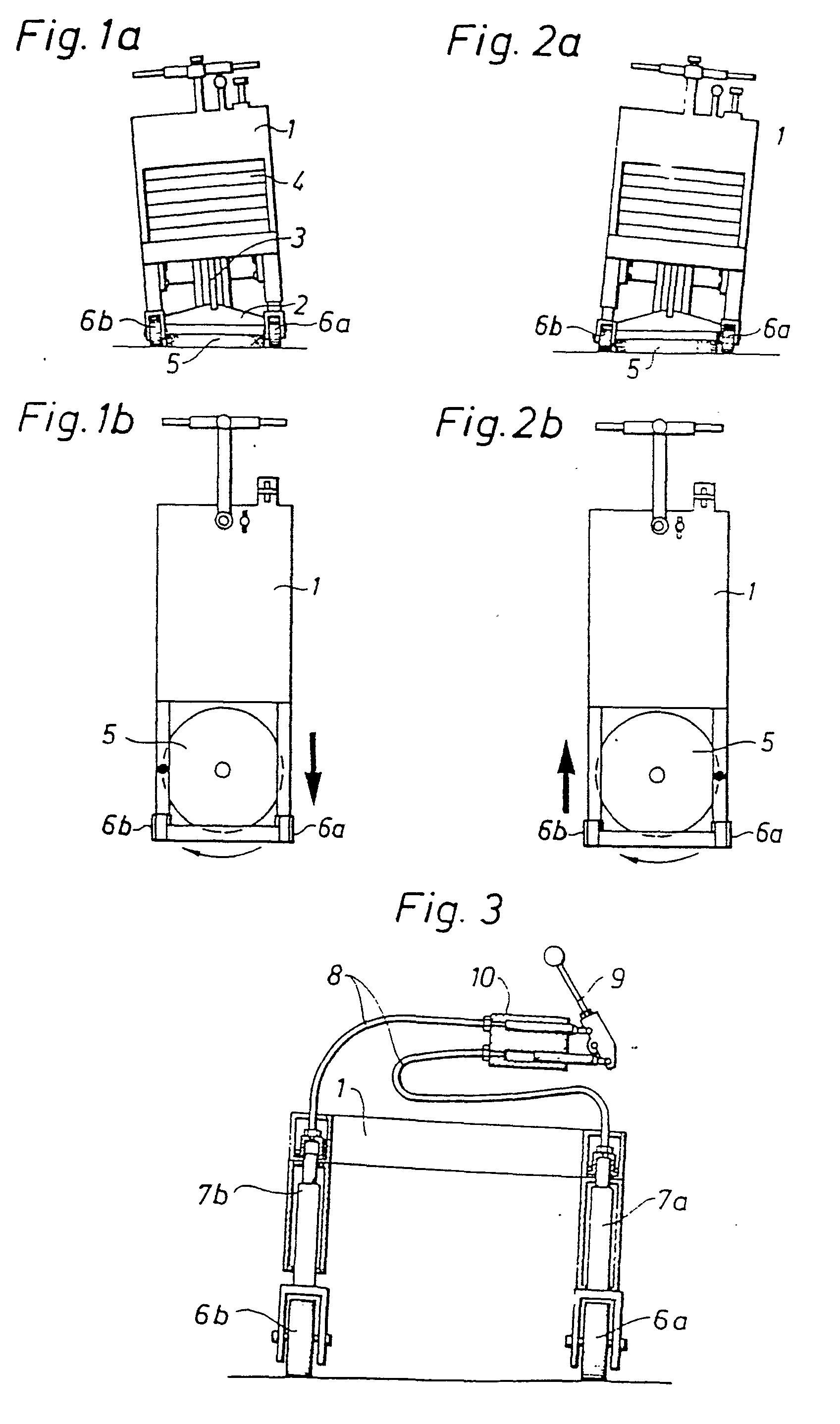
[0008] The invention will be described in more detail in the following by means of a design
model with reference to the appended drawing, where:
Figure 1a shows a front view and Figure 1b a a top view of a grinding machine moving
in a forward direction.
Figure 2a shows a front view and Figure 2b a top view of a grinding machine moving
in a rearward direction.
Figure 3 is a schematic diagram showing how tilting of the grinding machine is accomplished
by adjusting the height of its wheels.
[0009] The frame of the grinding machine is designated 1. It is fitted with two non-pivotable
wheels 6a, 6b positioned at its forward end on either side of a rotating grinding
or milling disc 2 on a vertical shaft 3 to which a grinding or milling tool 5 is resiliently
mounted. In addition, the frame is fitted with a wheel (not shown), steerable by the
operator, at its rear end. The shaft 3 is journalled in a bearing housing which, by
means of a system of links in the form of tierods, is mounted in the frame in a manner
permitting it to be raised and lowered. The bearing housing can be loaded with a number
of weights 4 corresponding to the grinding pressure it is desired to achieve without
causing a change in the normal forces acting on the non-pivotable wheels and the steerable
wheel respectively. Wheels 6a and 6b are each affixed to a hydraulic cylinder 7a and
7b, the other end of which is secured to frame 1. By means of hydraulic oil lines
8, hydraulic cylinders 7a and 7b are in communication with a double-acting hydraulic
cylinder 10 actuated by a lever 9.
[0010] By operating lever 9 the wheels 6a and 6b are raised and lowered so that the desired
tilting of frame 1 is achieved, causing the normal pressure of the grinding or milling
tool 5 against the floor to differ on the right and left side as viewed in the longitudinal
axis of the machine and accordingly giving rise to force resultants which move the
machine forwards or rearwards, depending on whether it is tilted to the right or to
the left.
[0011] The lever-operated double-acting hydraulic cylinder 10 is spring-loaded, which means
that it always returns to neutral position when the lever 9 is not actuated. Thus
it acts as a dead man's grip and automatically stops the propellent of the machine.
[0012] The same effect can of course also be achieved by arranging weights 4, which load
the bearing housing, in an adjustable asymmetric manner in relation to the right-hand
and left-hand side of the machine's longitudinal axis of symmetry.
1. A grinding and milling machine for smooth- finishing a flat surface like a floor
of concrete or similar hard material, consisting of a frame (1) which is equipped
with three wheels and in which a rotating grinding or milling disc (2) with a vertical
shaft (3) is mounted and loaded with weights (4), the associated grinding or milling
tool (5) being resiliently mounted on the grinding or milling disc characterized in
that the frame (1) of the machine at its forward end is carried on two non-pivotable
wheels (6a, 6b) positioned on respective sides of the rotating grinding or milling
tool (5), and at its rear end is carried on a wheel (not shown) steerable by the operator,
whereby the machine is arranged to be laterally tiltable by means of at least one
of the non-pivotable wheels (6a, 6b) being vertically adjustable.
2. A machine as in Claim 1, characterized in that at least one of the vertically adjustable
wheels (6a, 6b) is mounted on a hydraulic cylinder (7a, 7b) which by means of hydraulic
oil lines (8) is in communication with a double-acting hydraulic cylinder (10) actuated
by a lever (9).
3. A machine as in Claim 2, characterized in that the lever-operated double-acting
hydraulic cylinder (10) is spring-loaded in the neutral position which is always assumed
when the operating lever (9) is not actuated.
1. Schleif- und Fräsmaschine zum Glätten einer flachen Oberfläche etwa eines Fußbodens
aus Beton oder eines ähnlichen harten Materials, bestehend aus einem Rahmen (1) mit
drei Rädern, in dem eine rotierende Schleif- oder Fräsplatte (2) mit vertikaler Achswelle
(3) eingesetzt und mit Gewichten (4) belastet ist, wobei das mit der Platte verbundene
Schleif- oder Fräswerkzeug federnd auf die Schleif- oder Fräsplatte aufgesetzt ist,
dadurch gekennzeichnet, daß der Rahmen (1) der Maschine an seinem vorderen Ende von
zwei nicht schwenkbaren Rädern (6a, 6b) getragen wird, die an den entsprechenden Seiten
des rotierenden Schleif- oder Fräswerkzeuges (5) angeordnet sind, und an seinem rückwärtigen
Ende von einem Rad (nicht dargestellt) getragen wird, das vom Benutzer gesteuert werden
kann, wodurch die Maschine mit Hilfe von zumindest einem der nicht schwenkbaren Räder
(6a, 6b), die vertikal einstellbar sind, seitlich kippbar ist.
2. Maschine nach Anspruch 1, dadurch gekennzeichnet, daß zumindest eines der vertikal
verstellbaren Räder (6a, 6b) auf einen Hydraulik-Zylinder (7a, 7b) aufgesetzt ist,
der durch Hydraulik-Ölleitungen (8) mit einem doppelwirkenden Hydraulik-Zylinder (10)
verbunden ist, der mittels eines Handgriffes (9) betätigbar ist.
3. Maschine nach Anspruch 2, dadurch gekennzeichnet, daß der mittels eines Handgriffes
betätigbare doppelwirkende Hydraulik-Zylinder (10) in der neutralen Position, in der
er sich befindet, wenn der Handgriff (9) nicht betätigt wird, unter Federvorspannung
steht.
1. Une machine à meuler et à fraiser pour la finition lisse d'une surface plane telle
qu'un plancher en béton ou en matériau dur similaire, consistant en un bâti (1) qui
est muni de trois roues et dans lequel un disque rotatif de meulage ou de fraisage
(2) est monté sur un arbre vertical (3) et chargé avec des poids (4), l'outil combiné
de meulage et de fraisage (5) étant monté élastiquement sur le disque de meulage ou
de fraisage, caractérisée en ce que le bâti (1) de la machine est monté à son extrémité
avant sur deux roues non orientables (6a, 6b) disposées sur les côtés respectifs de
l'outil de meulage ou de fraisage (5), et qu'à son extrémité arrière, il est monté
sur une roue (non illustrée) pouvant être dirigée par l'opérateur, de sorte que la
machine est conçue pour pouvoir être inclinable latéralement au moyen de l'une au
moins des roues non orientables (6a, 6b) qui sont réglables verticalement.
2. Une machine selon la revendication 1, . caractérisée en ce que l'une au moins des
roues réglables verticalement (6a, 6b) est montée sur un vérin hydraulique (7a, 7b)
qui, au moyen de canalisations de fluides hydrauliques (8), communique avec un vérin
hydraulique à double effet (10) actionné par un levier (9).
3. Une machine selon la revendication 2, caractérisée en ce que le vérin hydraulique
à double effet (10) commandé par levier est maintenu par un ressort dans la position
neutre qui est toujours assurée quand le levier de manoeuvre (9) n'est pas actionné.