| (19) |
 |
|
(11) |
EP 0 240 112 B1 |
| (12) |
EUROPEAN PATENT SPECIFICATION |
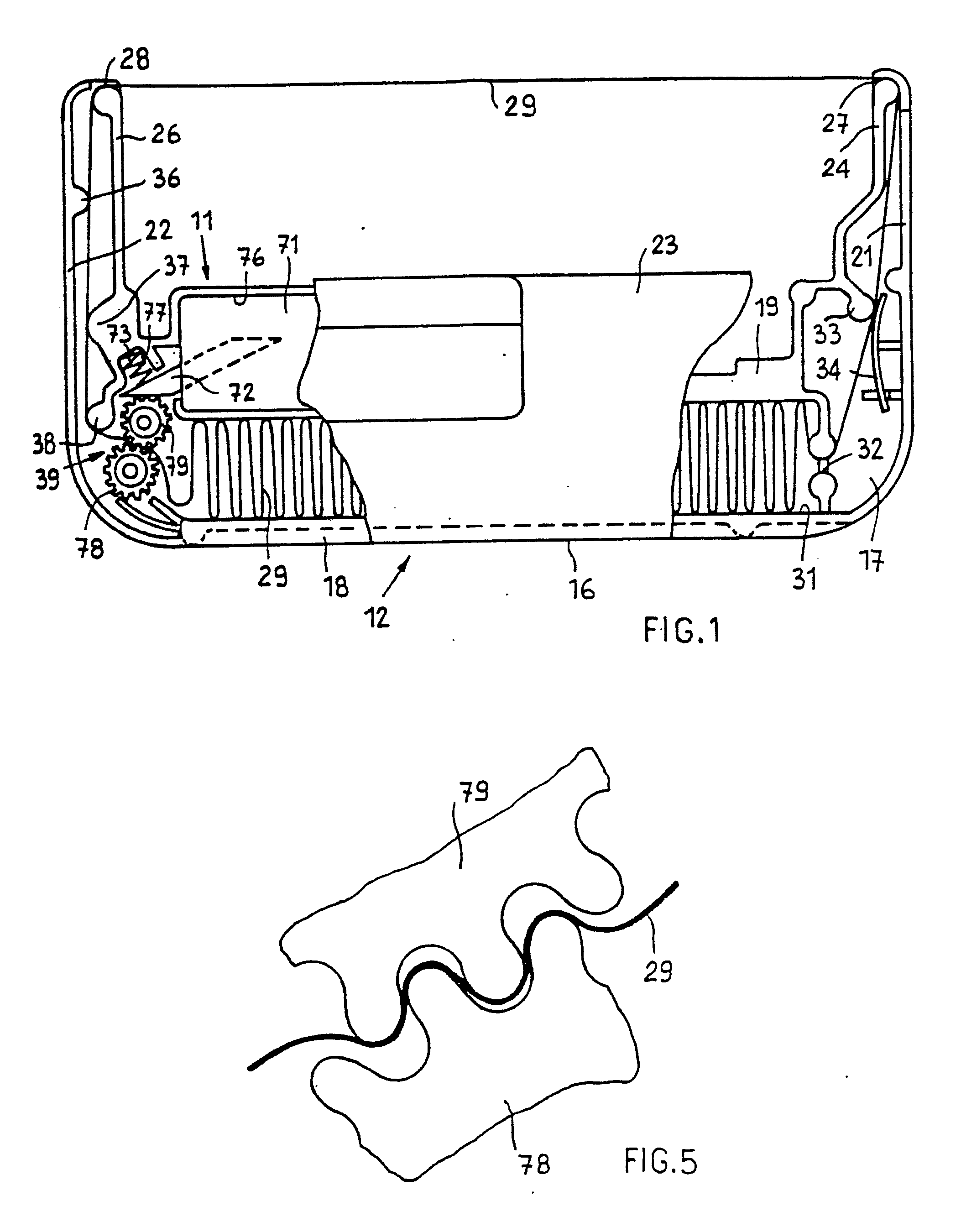
| (45) |
Mention of the grant of the patent: |
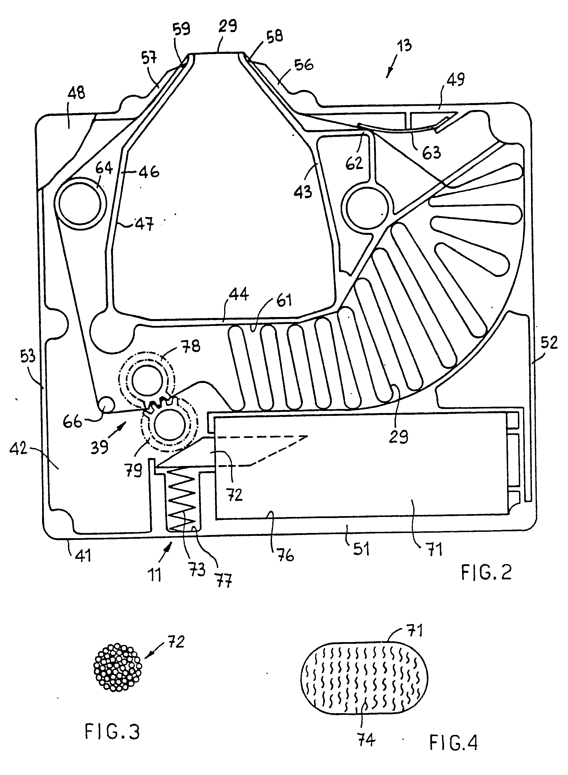
|
01.08.1990 Bulletin 1990/31 |
| (22) |
Date of filing: 06.02.1987 |
|
|
| (54) |
Cartridge for an inked ribbon with a re-inking device
Farbbandkassette mit Nachtränkvorrichtung
Cartouche de ruban encreur avec un dispositif de réencrage
|
| (84) |
Designated Contracting States: |
|
DE FR GB |
| (30) |
Priority: |
28.02.1986 IT 6716686
|
| (43) |
Date of publication of application: |
|
07.10.1987 Bulletin 1987/41 |
| (73) |
Proprietor: Ing. C. Olivetti & C., S.p.A. |
|
10015 Ivrea (Torino) (IT) |
|
| (72) |
Inventors: |
|
- Motta, Carlo
I-10013 Borgofranco
Torino (IT)
- Ricca, Aldo
I-10086 Rivarolo
Torino (IT)
- Trimboli, Walter
I-10154 Torino (IT)
- Fausto, Bruno
I-10154 Torino (IT)
|
| (74) |
Representative: Pears, David Ashley et al |
|
Broadlands
105 Hall Lane
GB-Upminster, Essex RM14 1AQ
GB-Upminster, Essex RM14 1AQ (GB) |
| (56) |
References cited: :
EP-A- 0 040 312
US-A- 2 103 494
US-A- 3 714 314
US-A- 4 043 682
US-A- 4 213 716
|
FR-A- 2 544 666
US-A- 2 732 824
US-A- 3 864 183
US-A- 4 071 133
|
|
| |
|
|
|
|
| |
|
| Note: Within nine months from the publication of the mention of the grant of the European
patent, any person may give notice to the European Patent Office of opposition to
the European patent
granted. Notice of opposition shall be filed in a written reasoned statement. It shall
not be deemed to
have been filed until the opposition fee has been paid. (Art. 99(1) European Patent
Convention).
|
[0001] The present invention relates to cartridges for an inked ribbon with a re-inking
device, of the type set forth in the pre-characterizing part of claim 1.
[0002] In a known cartridge of that type, (US-A 4 071 133) the metering means is a felt
member or a blade member in contact with the roller for producing the feed movement.
The felt metering member is partially housed in an inker and a spring urges the inker
with the metering means thereof against the feed movement roller. The re-inking device
suffers from the disadvantage of being of relatively high cost due to the need for
assembling the inker with the metering means thereof. In addition both the felt member
and the blade member do not ensure optimised constancy in respect of the feed flow
and run of the ink and thus make re-inking of the ribbon difficult.
[0003] A device according to the pre-characterizing part of claim 1 is known from FR-A 2
544 666. The bundle of fibres projecting from the reservoir bears endwise on the inking
roller and good pressure contact is thus dependent on maintenance of the properties
of the bundle of fibres and the reservoir over prolonged use.
[0004] The object of the present invention is to provide a low-cost re-inking device which
is simple, reliable and which at the same time ensures good contact with the inking
roller at all times.
[0005] To that end, the re-inking device for cartridges according to the invention is characterized
in the manner set forth in claim 1.
[0006] A preferred embodiment of the present invention is set forth in the following description
which is given by way of non-limiting example and with reference to the accompanying
drawings in which:
Figure 1 is a plan view of part of a first cartridge with the re-inking device according
to the invention,
Figure 2 is a plan view of part of a second cartridge using the re-inking device of
Figure 1, on an enlarged scale,
Figure 3 is a front view of part of the arrangement shown in Figure 1 on an enlarged
scale, illsutrating a detail thereof,
Figure 4 is a front view of part of the arrangement shown in Figure 1 on an enlarged
scale, showing another detail thereof, and
Figure 5 is a plan view of part of some details from Figures 1 and 2 on an enlarged
scale.
[0007] The re-inking device which is generally indicated by reference numeral 11 is used
by way of example in a cartridge 12 (see Figure 1) and a cartridge 13 (see Figure
2). Since the two cartridges 12 and 13 are not subject-matter of the present invention,
they are only partly described herein in order better to specify use of the re-inking
device 11. In particular the cartridge 12 (see Figure 1) comprises a casing 16 of
a substantially parallelepipedic elongate shape with the corners thereof connected
and rounded. The casing 16 comprises a bottom 17, a front wall 18, a rear wall 19,
two side walls, namely a right-hand side wall 21 and a left-hand side wall 22, and
a cover 23 which closes the casing 16 upwardly.
[0008] The cartridge 12 has two arms 24 and 26 which project from the rear wall 19 and which
each have an opening 27 and 28 respectively to permit a portion of inked ribbon 29
to be passed and guided therethrough. The inked ribbon 29 is of the closed loop type
and is disposed in randomly distributed turns in a magazine 31 in the casing 16. The
magazine 31 has an exit 32 for the inked ribbon 29 to pass therethrough. The ribbon
29 is pinched between a fixed pin portion 33 and a resilient blade member 34 to prevent
more turns of ribbon from coming out of the magazine and to tension the ribbon 29.
The ribbon 29 then passes into the opening 27, coming out of the casing 16, and re-enters
by way of the opening 28 and, being guided by fixed pin portions 36, 37 and 38, is
engaged by a pair of rollers which are generally indicated by reference numeral 39,
for the unidirectional feed movement, and is then passed into the magazine 31 again.
[0009] The cartridge 13 (see Figure 2) comprises a casing 41 formed by a bottom 42 and a
series of internal walls 43, 44 and 46 defining a space or cavity 47. The casing 41
is closed upwardly by a cover 48, a rear wall 49, a front wall 51 and a right-hand
side wall 52 and a left-hand side wall 53.
[0010] The cartridge 13 comprises two suitably shaped arms 56 and 57 which project from
the rear wall 49 and which at their ends have two openings 58 and 59 respectively
to permit a portion of the inked ribbon 29 to be passed therethrough and guided on
the exterior of the cartridge. The inked ribbon 29 is the same as that in the cartridge
12 (Figure 1), is of the closed loop type and is disposed in randomly distributed
turns in a magazine 61 (see Figure 2) in the casing 41. The inked ribbon 29 issues
from the magazine 61, and is then gripped between a fixed wall 62 and a resilient
blade member 63 for preventing more turns from coming out of the magazine and for
tensioning the ribbon 29. The ribbon 29 then passes into the opening 58, leaving the
casing 41, and re-enters by way of the opening 59 and, guided by fixed pin portions
64 and 66, is engaged by the pair of rollers generally indicated by reference numeral
39 for the unidirectional feed movement and is then passed into the magazine 61 again.
[0011] To simplify the description, identical parts of the two cartridges 12 and 13 are
denoted by the same reference numerals: re-inking device 11, inked ribbon 29 and pair
of feed rollers 39.
[0012] Referring to Figures 1 and 2, the re-inking device 11 comprises a reservoir for the
ink or inker 71, an ink metering means 72 and a spring 73. The inker 71 is of a parallelepipedic
shape of rectangular section with rounded edges, is of a material comprising polyester
fibres with external co-extrusion and is capable of containing ink 74 (see Figure
4) in such an amount that the ink 74 occupies only half the volume of the inker 71.
The inker 71 is housed in a seat 76 in the casings 16 (Figure 1) and 41 (Figure 2).
[0013] The ink metering means 72 is substantially cylindrical and its longitudinal section
is of rhomboidal shape while its cross-section is circular (see Figure 3). It is formed
by a rigid bunch of capillary filaments of elasticated nylon fibres. The fibres are
slightly impregnated with a phenol resin which however leaves capillary spaces between
the filaments such as to provide for capillary flow of the ink 74 therethrough. The
number of filaments contained in the rigid bunch of capillary filaments is of a predetermined
density such as to provide a level of permeability such as to optimise the amount
and flow of the ink 74 from the inker 71 to the pair of rollers 39. The spring 73
is fitted between a seat 77 of the casings 16 (Figure 1) and 41 (Figure 2) and the
outside longitudinal edge of the inker 72.
[0014] The pair of feed rollers 39 (see Figures 1 and 2) comprises two toothed wheels 78
and 79 in which the addenda of the teeth are of rounded section. The spring 73 holds
the ends of the filaments of the ink metering means 72 always in engagement with the
outside surface of the teeth of the toothed wheel 79 and thus the ink 74 is deposited
on the outside surface of the teeth and during the rotary movement of the wheels 78
and 79 (see Figure 5), besides causing unidirectional feed movement of the ribbon
29, the wheel 79 transfers the ink 74 which is on the outside rounded surface of the
teeth, as can be clearly seen from Figure 5. The mode of operation and the rotary
movement of the feed rollers 39 are substantially the same as those described in our
British Patent Specification GB 1595447.
[0015] It will be apparent therefore that the ink metering means 72, being rigid, always
remains in contact with the cylindrical surface of the teeth of the toothed wheel
79, due to the force of the spring 76 which acts on the longitudinal edge of the metering
means 72.
[0016] Since the bunch of fibres has a rhomboidal shape, it is apparent that both its ends
are bevelled ends.
1. A cartridge for an inked ribbon with a re-inking device, comprising a magazine
(31, 61) for housing the ribbon (29) and a pair of rollers (39) for the feed movement
of the ribbon, in which the re-inking device comprises an ink reservoir (71) and an
ink metering means (72) for transferring ink from the reservoir to one of the rollers
(79), in which the metering means (71) comprises a substantially rigid bunch of capillary
fibres having permeable ends and cross-sections, and in which a first end is inserted
into the reservoir (71) and a second end cooperates with the said one roller (79)
for capillary flow of the ink from the reservoir to this roller, characterized in
that the first and the second ends of the bunch (72) of fibres are bevelled ends,
and spring means (73) are provided which act on a side surface of the bunch (72) of
fibres adjacent to the second bevelled end to urge the said second bevelled end against
the said one roller.
2. A cartridge according to claim 1, characterized in that the rollers (39) are toothed
wheels of which the teeth have rounded crests.
3. A cartridge according to claim 1 or 2, characterized in that the bunch (72) of
capillary fibres comprises elasticated nylon fibres.
4. A cartridge according to claim 3, characterized in that the nylon fibres are impregnated
with phenol resin, which leaves capillary spaces between the filaments for the capillary
transmission of the ink.
5. A cartridge according to any of claims to 4, characterized in that the bunch (72)
of capillary fibres has a longitudinal section of rhomboidal shape.
6. A cartridge according to any of claims 1 to 5, characterized in that the reservoir
(71) is of substantially parallelepipedic shape and is made of polyester fibres with
external co-extrusion, in which the external co-extrusion has an open end, in which
the bevelled first end of the bunch of fibres (72) is inserted between the fibres
of the container by way of the open end of the co-extrusion to hold the fibres of
the reservoir in contact with the fibres of the bunch (72).
7. A cartridge according to claim 2 or any of claims 3 to 6 insofar as dependent thereon,
characterized in that the resilient means (73) comprise a spring which holds the ends
of the capillary fibres against the rounded ends of the teeth of the one roller (79).
8. A cartridge according to claim 7, characterized in that the reservoir (71) is disposed
in a first housing (76) adjacent to the two rollers (39) and to the spring (73) contained
in a second housing (77) adjacent to the first housing.
9. A cartridge according to any of the preceding claims, characterized in that the
number of filaments contained in the bunch (72) is of a predetermined density so as
to provide a degree of permeability such as to optimise the amount and the flow of
the ink from the reservoir (71) to the one roller (79).
10. A cartridge according to any of the preced; ing claims, characterized in that the ribbon (29) is of the closed loop type and
is disposed in randomly distributed loops.
1. Farbbandkassette mit Nachtränkvorrichtung, wobei die Kassette aufweist: ein Magazin
(31, 61) zur Aufnahme des Farbbands (29) und ein Paar Rollen (39) für die Vorschubbewegung
des Farbbands, wobei die Nachtränkvorrichtung einen Tintenvorratsbehälter (71) und
ein Tintendosiermittel (72) zum Übertragen von Tinte aus dem Vorratsbehälter auf eine
der Rollen (79) aufweist, wobei das Dosiermittel (72) ein weitgehend starres Bündel
kapillarer Fasern mit durchlässigen Enden und Querschnitten aufweist und wobei ein
erstes Ende in den Vorratsbehälter (71) eingeführt ist und ein zweites Ende mit der
erwähnten einen Rolle (79) für einen kapillaren Durchfluß der Tinte aus dem Vorratsbehälter
zu dieser Rolle zusammenwirkt, dadurch gekennzeichnet, daß das erste und das zweite
Ende des Faserbündels (72) abgeschrägte Enden sind und Federmittel (73) vorgesehen
sind, die auf eine Seitenfläche des Faserbündels (72) neben dem zweiten abgeschrägten
Ende einwirken, um das erwähnte zweite abgeschrägte Ende gegen die erwähnte eine Rolle
zu drücken.
2. Kassette nach Anspruch 1, dadurch gekennzeichnet, daß die Rollen (39) Zahnräder
sind, deren Zähne abgerundete Köpfe haben.
3. Kassette nach Anspruch 1 oder 2, dadurch gekennzeichnet, daß die Bündel (72) aus
Kapillarfasern elastische Nylonfasern aufweist.
4. Kassette nach Anspruch 3, dadurch gekennzeichnet, daß die Nylonfasern mit Phenolharz
imprägniert sind, das Kapillarräume zwischen den Fasern zur kapillaren Übertragung
der Tinte freiläßt.
5. Kassette nach einem der Ansprüche 1 bis 4, dadurch gekennzeichnet, daß das Bündel
(72) aus kapillaren Fasern einen Längsquerschnitt in Rhombusform aufweist.
6. Kassette nach einem der Ansprüche 1 bis 5, dadurch gekennzeichnet, daß der Vorratsbehälter
(71) weitgehend die Form eines Parallelepipeds aufweist und aus Polyesterfasern mit
externer Koextrusion hergestellt ist, wobei die externe Koextrusion ein offenes Ende
aufweist, bei dem das abgeschrägte erste Ende des Faserbündels (72) zwischen die Fasern
des Behälters mittels des offenen Endes der Koextrusion eingeführt ist, um die Fasern
des Vorratsbehälters mit den Fasern des Bündels (72) in Berührung zu halten.
7. Kassette nach Anspruch 2 oder einem der Ansprüche 3 bis 6, soweit sie auf diesen
zurückbezogen sind, dadurch gekennzeichnet, daß die elastischen Mittel (73) eine Feder
aufweisen, die die Enden der kapillaren Fasern an den abgerundeten Enden der Zähne
der einen Rolle (79) halten.
8. Kassette nach Anspruch 7, dadurch gekennzeichnet, daß der Vorratsbehälter (71)
in einem ersten Gehäuse (76) neben den beiden Rollen (39) und der Feder (73) angeordnet
ist, die in einem zweiten Gehäuse (77) neben dem ersten Gehäuse angeordnet ist.
9. Kassette nach einem der vorstehenden Ansprüche, dadurch gekennzeichnet, daß die
Anzahl der Fasern in dem Bündel (72) eine vorbestimmte Dichte aufweist, die so gewählt
ist, daß sich ein solcher Durchlässigkeitsgrad ergibt, daß die Menge und der Durchfluß
der Tinte aus dem Vorratsbehälter (71) zu der einen Rolle (79) optimiert ist.
10. Kassette nach einem der vorstehenden .Ansprüche, dadurch gekennzeichnet, daß das
Farbband (29) ein endloses geschlossenes Band und in willkürlich verteilten Schleifen
angeordnet ist.
1. Une cartouche pour un ruban encré avec un dispositif de réencrage, comprenant un
magasin (31, 61) pour recevoir le ruban (29) et une paire d'organes rotatifs (39)
pour assurer le mouvement d'avancement du ruban, cartouche dans laquelle le dispositif
de réencrage comprend un réservoir d'encre (71) et un moyen (72) de dosage d'encre
pour transférer de l'encre du réservoir vers un des organes rotatifs (79), le moyen
de dosage (71) comprenant un faisceau sensiblement rigide de fibres capillaires ayant
des sections droites et des extrémités perméables, et où une première extrémité est
engagée dans le réservoir (71) et une seconde extrémité coopère avec un des organes
rotatifs précités (79) pour produire un écoulement capillaire de l'encre du réservoir
jusqu'à cet organe rotatif, caractérisée en ce que les première et seconde extrémités
du faisceau (72) de fibres sont des extrémités biseautées et il est prévu des moyens
élastiques (73) qui agissent sur une surface latérale du faisceau (72) de fibres dans
une zone adjacente à la seconde extrémité biseautée pour pousser ladite seconde extrémité
biseautée contre tedit organe rotatif.
2. Une cartouche selon la revendication 1, caractérisée en ce que les organes rotatifs
(39) sont des roues dentées dont les dents comportent des crêtes arrondies.
3. Une cartouche selon une des revendications 1 ou 2, caractérisée en ce que le faisceau
(72) de fibres capillaires comprend des fibres de nylon rendues élastiques.
4. Une cartouche selon la revendication 3, caractérisée en ce que les fibres de nylon
sont imprégnées d'une résine phénolique, qui laisse subsister des espaces capillaires
entre les filaments pour la transmission capillaire de l'encre.
5. Une cartouche selon une quelconque des revendications 1 à 4, caractérisée en ce
que le faisceau (72) de fibres capillaires a une section longitudinale en forme de
losange.
6. Une cartouche selon une quelconque des revendications 1 à 5, caractérisée en ce
que le réservoir (71) a une forme sensiblement parallélépipédique et est constitué
de fibres de polyester avec partie externe co-extrudée, cette partie externe co-extrudée
comportant une extrémité ouverte et la première extrémité biseautée du faisceau de
fibres (72) étant insérée entre les fibres du réservoir par l'intermédiaire de l'extrémité
ouverte de la partie co-extrudée afin de maintenir les fibres du réservoir en contact
avec les fibres du faisceau (72).
7. Une cartouche selon la revendication 2 ou une quelconque des revendications 3 à
6, pour autant qu'elles en soient dépendantes, caractérisée en ce que les moyens élastiques
(73) comprennent un ressort qui maintient les extrémités des fibres capillaires contre
les extrémités arrondies des dents de l'organe rotatif précité (79).
8. Une cartouche selon la revendication 7, caractérisée en ce que le réservoir (71)
est disposé dans un premier boîtier (76) adjacent aux deux organes rotatifs (39) et
au ressort (73), contenu dans un second boîtier (77) adjacent au premier boîtier.
9. Une cartouche selon une quelconque des revendications précédentes, caractérisée
en ce que le nombre de filaments contenus dans le faisceau (72) est d'une densité
prédéterminée de façon à établir un degré de perméabilité permettant d'optimiser la
quantité et l'écoulement de l'encre du réservoir (71) vers l'organe rotatif précité
(79).
10. Une cartouche selon une quelconque des revendications précédentes, caractérisée
en ce que le ruban (29) est du type à boucle fermée et est disposé avec ondulations
réparties au hasard.