| (19) |
 |
|
(11) |
EP 0 240 151 B1 |
| (12) |
EUROPEAN PATENT SPECIFICATION |
| (45) |
Mention of the grant of the patent: |
|
08.08.1990 Bulletin 1990/32 |
| (22) |
Date of filing: 26.02.1987 |
|
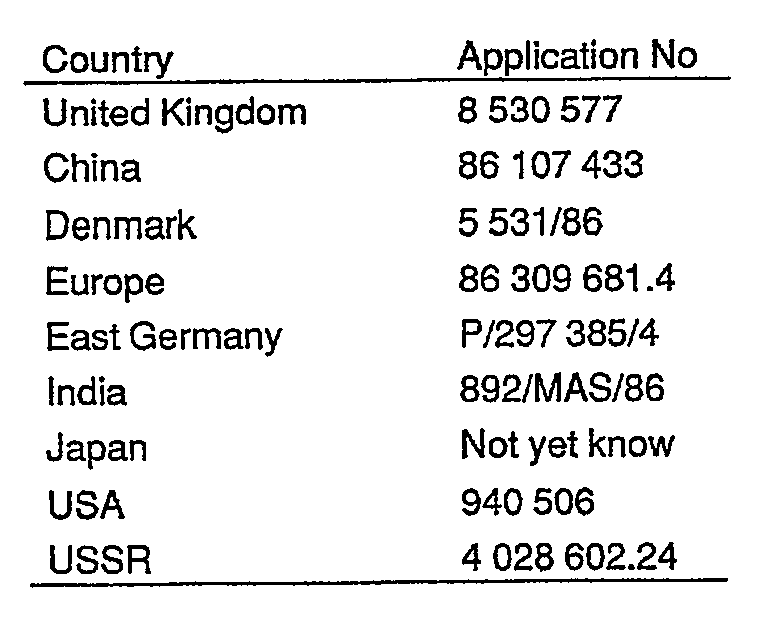
|
| (54) |
Metrological apparatus
Metrologischer Apparat
Appareil métrologique
|
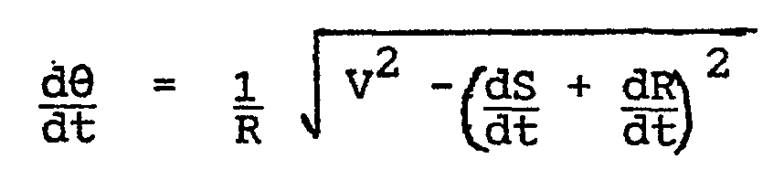
| (84) |
Designated Contracting States: |
|
CH DE GB IT LI SE |
| (30) |
Priority: |
04.03.1986 GB 8605324
|
| (43) |
Date of publication of application: |
|
07.10.1987 Bulletin 1987/41 |
| (60) |
Divisional application: |
|
89201143.8 / 0335474 |
|
89201828.4 / 0342770 |
| (73) |
Proprietor: RANK TAYLOR HOBSON LIMITED |
|
Leicester LE4 7JQ (GB) |
|
| (72) |
Inventors: |
|
- Lane, Hugh Rogers
South Croxton
Leicster LE7 8RT (GB)
- Onyon, Peter Dean
Loughborough LE11 2BQ (GB)
|
| (74) |
Representative: Beresford, Keith Denis Lewis et al |
|
BERESFORD & Co.
2-5 Warwick Court
High Holborn
London WC1R 5DJ
London WC1R 5DJ (GB) |
| (56) |
References cited: :
EP-A- 0 027 186
DE-A- 2 654 839
GB-A- 2 172 707
US-A- 4 167 066
|
EP-A- 0 068 082
FR-A- 2 282 618
US-A- 3 741 659
|
|
| |
|
|
|
|
| |
|
|
|
Remarks: |
|
Divisional application 89201143.8 filed on 26/02/87. |
|
| Note: Within nine months from the publication of the mention of the grant of the European
patent, any person may give notice to the European Patent Office of opposition to
the European patent
granted. Notice of opposition shall be filed in a written reasoned statement. It shall
not be deemed to
have been filed until the opposition fee has been paid. (Art. 99(1) European Patent
Convention).
|
[0001] This invention relates to metrological apparatus comprising a rotatable member for
receiving a workpiece, first drive means for rotating said member, a sensor for sensing
the surface of a workpiece on the rotatable member during rotation thereof, means
supporting said sensor for movement relative to said workpiece receiving member, second
drive means for effecting said movement of said sensor, and digital computer means
arranged to receive signals derived from said sensor for providing metrological data.
[0002] Such an apparatus is disclosed in German specification 2 654 839.
[0003] The object of the invention is to provide an apparatus in which the manner in which
measurements are made is improved. This is achieved in accordance with the invention
in that the computer means is operable to control the drive means in response to signals
derived from the sensor to cause the sensor to transverse the surface of the workpiece
at a substantially constant speed.
[0004] In a preferred embodiment, the digital computer means is operable to control relative
movement between the workpiece and the sensor in response to the signals derived from
the sensor such that the sensor follows the workpiece surface and to provide the metrological
data in dependence both on the signals and on the movement of the sensor.
[0005] Thus, in this way, a sensor having extremely high resolution, such as a resolution
of better than 20 nanometres, preferably 12 nanometres, but a small range of operation,
such as less than 0.4 mm, can be employed to enable the sensing of the minutest variations
in form, whilst large features of form can be accommodated by the actuation of the
drive means under control of the digital computer, and the derivation of the metrological
data is both in dependence upon the transducer output and in dependence upon the movement
of the sensor. The position of the sensor should therefore be determinable also with
high resolution although in practice it is not necessary that this resolution be so
high as that provided by the sensor itself. Thus, for example, whilst as already indicated
the sensor should preferably have a resolution to better than 20 nanometres the resolution
to which the position of the sensor may be determined when moved by the second drive
means might only be to better than say 500 nanometres, preferably to say 200 nanometres
but even this is an improvement of at least an order of magnitude compared to prior
art apparatus.
[0006] The size of the features which can be accommodated by movement of the sensor will
depend upon the range of movement of the sensor. In practice, the sensor may be movable
at least 100 mm in the radial direction and at least 100 mm in the axial direction.
In a preferred specific example, the sensor is movable radially through a distance
of 200 mm and axially through a distance of 500 mm.
[0007] The invention is described further by way of example with reference to the accompanying
drawings in which:
Figure 1 is a perspective view of metrological apparatus according to an embodiment
of the invention;
Figure 2 is a perspective view showing part of the apparatus of Figure 1 in more detail;
Figure 3 is an elevation in the direction of arrow III of Figure 2;
Figure 4 is an elevation in the direction of arrow IV of Figure 2;
Figure 5 is a block diagram illustrating a computer sysem incorporated in the apparatus
of Figure 1;
Figure 6 is a diagram of a cam for illustrating a preferred function which may be
carried out in accordance with a preferred aspect of the invention; and
Figures 7, 8 and 9 are diagrams illustrating methods of measuring flatness, cylindricity
and conicity respectively in accordance with further preferred aspects of the invention.
[0008] With reference to Figure 1, metrological apparatus comprises a bench 2 provided with
a turntable 4 for supporting a workpiece (not shown). A carriage 6 is supported for
vertical movement on a column 8 and carries a horizontally movable arm 10. A stylus
12 for engaging the surface of the workpiece is comprised in a linear transducer 14,
which may be inductive or capacitative for example, which is carried on one end of
an arm 16 whose other end is attached to the free end of the arm 10 for pivotal movement,
in the direction shown by arrow 18, about an axis 20 which is at 45
° to the horizontal.
[0009] As best seen in Figure 2, the arm 16 is pivotable through 180° about the axis 20
between the end positions shown in Figure 2 in full and chain dotted lines respectively.
In the full line position, the stylus 12 is vertical and in the broken line position
the stylus 12 is horizontal. The arrangement is such that the tip of the stylus 12a
is located in substantially the same position in a radial plane of the turntable 4
when the arm 16 is in either of the two positions shown in Figure 2. An electric motor
3 mounted in the arm 10 is coupled to the arm 16 through a worm and wheel transmission
5 for driving the arm 16 between its two end positions. The stylus 12 and transducer
14 are arranged so that the stylus 12 can be deflected relative to the transducer
14 in only one direction. However, the transducer 14 is mounted in the arm 16 for
rotation about an axis 7, preferably through 270
° in 30
° steps. Thus, for example, if the transducer 14 is rotated about axis 7 through 90
° this changes by 90° the plane within which the stylus 12 is deflectable. A motor
9 is mounted in the arm for effecting rotation of the transducer 14. When the arm
16 is in the full line position shown in Figure 2 with the stylus 12 vertical, for
example for sensing an internal surface of a workpiece placed on the turntable 4,
the transducer 14 will generally be maintained in a position in which the stylus 12
is deflectable in a radial plane relative to the turntable 4. However, when the arm
16 is in the broken line position shown in Figure 2 with the stylus 12 horizontal,
the transducer 14 may be rotated either to the position in which the stylus 12 is
deflectable in a horizontal plane or to a position in which the stylus 12 is deflectable
in a vertical plane. In the former position, a side surface of a workpiece may conveniently
be sensed and in the latter position an upwardly facing surface may conveniently be
sensed. Surfaces facing in other directions may be sensed by rotating the transducer
14 about axis 7 to a position in which the stylus 12 is deflectable in a plane generally
normal to the surface to be sensed.
[0010] As seen in Figure 3, a motor 35 is provided in the carriage 6 for driving the arm
10 in the horizontal direction indicated by arrow 11, drive being transmitted from
the motor 35 to the arm 10 through a rack and pinion arrangement 13 or other suitable
means such as a ball screw. Movement of the arm 10 in the direction of arrow 11 causes
the transducer 14 to be moved horizontally so that the tip 12a of the stylus 12 is
moved radially inwardly or outwardly relative to the axis of the turntable 4, the
tip 12a remaining in the radial plane throughout this movement. Light from a source
15 mounted in the carriage 6 is directed towards a linear optical grating 19 carried
by the arm 10 and reflected therefrom to a phototransducer 21 which provides output
signals, preferably quadrature signals, from which the position and velocity of the
arm 10 can be derived. As also seen in Figure 3, a further phototransducer 23 provides
signals from which the position and rotational velocity of the turntable 4, which
is driven by a motor 33, can be derived with the aid of a light source 25 and optical
grating 27 movable with the turntable 4.
[0011] As seen in Figure 4, a motor 37 carried by the carriage 6 cooperates with a rack
and pinion arrangement 39 (or other suitable means such as a sprocket wheel and chain)
for driving the carriage 6 vertically in the direction of arrow 47. A constant force
spring (not shown) is provided for counterbalancing this movement. A further optical
grating 43 mounted in the column 8 reflects light from a source 27 carried by the
carriage 6 to a phototransducer 31 also carried by the carriage 6 so that the transducer
31 may provide signals, preferably quadrature signals, from which the position and
speed of movement of the carriage 6 may be derived.
[0012] As seen in Figures 1 and 5 a host computer 22, which is provided with a keyboard
24, disc drive 26 and printer 28, is located on the bench 2 and is used for controlling
the metrological apparatus, processing the measurements obtained and outputting the
required metrological data. The host computer may, for example, be an IBM compatible
PC.
[0013] As shown in Figure 5, the apparatus includes a number of microprocessors 30, 32,
34, 36, 38 and 40. Microprocessor 30 is used as a master controller and receives instructions
from the host 22 as to the operations which are to be performed by the apparatus,
Such instructions are stored by the master controller 30 which, in accordance with
programs stored in memory associated with the master controller, instructs and controls
the remaining microprocessors, via a slave driver processor 30a, as to the action
to be taken in order to carry out the instructions supplied by the host 22. Each of
the remaining microprocessors also has memory associated with it storing the routines
necessary for the performance of the instructions received from the master controller
30. Thus, microprocessors 32, 34, 36 and 38 are designated as slaves.
[0014] Slave 32 controls the speed of rotation of the turntable 4. Slave 34 controls radial
movement of the arm 10. Slave 36 controls vertical movement of the carriage 6. Slaves
32, 34 and 36 all preferably control the speeds of the respective motors 33, 35 and
37 in accordance with the teachings of our copending Patent Applications identified
as follows:
[0015] Slave 38 receives instructions from communication network 45 and controls centring
and levelling motors 38a wherein the turntable 4 is displaced horizontally and/or
pivotally for centring and levelling of a workpiece prior to performing measurements.
The arrangements for centring and levelling are preferably in accordance with the
disclosure of or European patent No. 87301711 (Publication No. EP 0 240 150) being
filed simultaneously herewith and claiming priority from British Patent Application
Nos. 8 605 325 and 8 624 396 in which the inventors are Anthony Bruce Barnaby and
Michael Walter Mills.
[0016] Microprocessor 40 receives data from gauging circuit 41 which receives and digitizes
the signal output by the transducer 14 and from each of three interpolators 42, 44
and 46, which respectively receive signals from photoelectric transducers 23, 21 and
31 that detect the rotary movement of the turntable 4, the radial (horizontal) movement
of the arm 10 and the vertical movement of the carriage 6 respectively. The interpolators
function to provide data representing the precise positions of the turntable 4, arm
10 and carriage 6 to a resolution to a small fraction of the pitch of the optical
gratings 27, 19 and 43. In the preferred embodiment, the interpolators provide resolution
of the position of the transducer 14 in the radial (horizontal) direction to about
200 nanometres and in the axial (vertical) direction to about 500 nanometres and the
rotational position of the workpiece can be resolved to about 3 arc seconds. The invention
is not restricted to any specific resolution but it is preferred that resolution in
the radial and vertical directions should be better than 1 micron and the rotational
resolution should be better than 100 arc seconds, preferably better than 10 arc seconds.
As already indicated, the transducer 14 preferably provides an output signal which
resolves the position of the tip 12a of the stylus 12 to better than 20 nanometres,
preferably 12 nanometres. Thus, high resolution data as to the deflection of the stylus
12 and the disposition of the transducer 14 in the radial (11) and vertical (Z) directions
and the precise rotational position (0) of the turntable 4 is continually supplied
to the micro- prozessor 40 during a measuring operation. This data is logged and stored
by the microprocessor 40 and supplied to the host 22 for the performance of the required
calculations of this data in accordance with programs stored in memory associated
with the host 22.
[0017] Accordingly, and by way of summary, the architecture shown in Figure 5 is such that
the computers are arranged in three levels. The host 22 represents a first level and
permits the input of instructions from an operator, the transfer of appropriate instructions
to the master controller, and the reception of data from the data logger 40. The host
22 performs calculations on that data in order to provide the required information.
The second level is represented by the master controller 30 which, upon receipt of
instructions from the host 22, transmits, in accordance with programs stored in memory
associated with the master controller 30, appropriate instructions to the various
slaves, via the slave driver 30a as necessary to perform the operation instructed
by the host. The slaves 32, 34, 36 and 38, and the data logger 40, represent the third
level and carry out, in accordance with programs stored in memory associated with
them respectively, the detailed functions necessary to perform the operations instructed
by the master controller on the instructions of the host 22. Preferably the master
controller is arranged so that successive instructions received from the host 22 may
be stored simultaneously in different portions of the associated memory so that these
instructions may be acted upon in turn by the master controller 30.
[0018] It has already been mentioned that the transducer 14 is a linear transducer. Thus,
the signal which it outputs is representative of the degree of deflection of the stylus
12. However, as also already indicated, transducers providing the required high degree
of resolution, for example resolution to better than 20 nanometres suffer from the
problem that their range of operation i.e. the range of movement of the tip 12a of
the stylus 12 within which a linear output signal with the required resolution is
provided, is highly limited. Specifically, transducers with a suitable resolution
may have a range of no more than 0.4 mm. To overcome this problem in accordance with
an important preferred aspect of the invention, the master controller, 30, upon receiving
information that the signal from the gauging circuit 41 has exceeded a predetermined
threshold, transmits an instruction to slave 34 to activate the motor 35 whereby the
arm 10 is displaced until the signal output by the gauging circuit 41 is returned
to a predetermined value, defined as a null value (which may, for example, be zero).
Such instruction is sent when the transducer 14 is in a position in which the stylus
12 is deflectable in a radial plane with the arm 16 in either of the positions shown
in Figure 2. If the arm 16 is in the broken line position shown in Figure 2, with
the stylus 12 horizontal, and if the transducer 14 is rotated to the position in which
the stylus is deflectable in a vertical plane (i.e. parallel to the axis of the turntable
4) the master controller 30 sends an instruction to the slave 36 to activate the motor
37 when the output from the gauging circuit 41 exceeds the predetermined threshold.
Further, the master controller 30 is arranged so that, in appropriate circumstances,
activation of the motor 33 for rotating the turntable may be effected under control
of signals from the transducer 14 such that when the signal therefrom exceeds a predetermined
threshold the motor 33 is actuated so that the workpiece is moved as necessary to
permit the transducer 14 to follow the surface of the workpiece as it moves in the
horizontal and/or vertical direction. Thus, in all of these cases, the stylus 12 is
caused to follow the surface of the workpiece during measurement he workpiece on the
turntable 4. As a result high resolution measurements can be obtained while nevertheless
accommodating large features of form since when such large features are encountered
by the stylus the arm 10 or carriage 6 or turntable 4 is moved as appropriate so that
the tip of the stylus follows the workpiece surface without the stylus being deflected
beyond its range of operation. The host computer 22 obtains the metrological information
required, for example as to form or errors in form, both from the signals derived
from the transducer 14 and the signals derived from the phototransducers 23, 21, 31
and the associated interpolators 42, 44 and 46.
[0019] In accordance with the invention, the speed at which the stylus traverse the workpiece
surface may be kept constant, by varying the speed of the motors driving the turnable
4 and/or the arm 10 and/or the carriage 6, so as to enable the gathering of data in
a preferred manner for example to provide constant surface bandwith whereby the results
of measuring identical surface features at different radii are also ondentical and
dependent only on the surface speed selected. In particular, it is preferred that
data be taken at points on the surface of the workpiece at fixed distances apart and
accordingly, with the arrangement under description, this may be archieved regardless
of, for example, different curvatures of different portions of the surface, without
varying the data collection rate by varying one or more of the speeds mentioned in
order to compensate for the difference on curvatures, for example. In order to accomplish
this, the master controller 30 reads positional data from the interpolators 42, 44
and 46 and the gauging circuit 41, the speed of the appropriate motors being varied
in accordance with this received data and with programs stored in memory associated
with the master controller 30.
[0020] As an example of the foregoing, Figure 6 illustrates a cam 50 whose profile is to
be measured by taking measurements at positions spaced apart by a distance ds. At
portion 52 of the cam where distance ds is at a radius rl from the centre of rotation
54 and subtends at angle a, the speed of rotation of the turntable 4, in order to
enable collection of data at a constant rate, will have to differ from that utilised
when measuring portion 53 of the cam, where ds is at a radius r2 and subtends an angle
b. Thus, the master controller has associated with it programs for varying the speed
of rotation of the turntable 4 taking these parameters into account in order that
data may be collected at a constant rate at constant incremental positions of the
stylus on the surface being measured. To achieve this, the speed of rotation of the
turntable may be controlled in accordance with the following equation:
where V is the required constant speed of traverse of the transducer over the workpiece
surface, s is the signal from the linear output transducer 14 and R is the signal
derived by the interpolator 44 from the transducer 21 indicating the radial position
of the transducer 14.
[0021] With reference to Figure 7, a preferred operation for the measurement of flatness
is illustrated. In Figure 7, a surface 60 of a workpiece (not shown) placed upon the
turntable 4 is traversed by the stylus 12 in a spiral path 62. This is achieved by
causing the arm 10 to be moved radially inwardly or outwardly accordingly to whether
the measurement is started near the centre or near the periphery of the surface 60,
whilst rotating the turntable 4. In one preferred mode of operation, the speed of
rotation of the turntable is varied, as a linear function of the distance of the stylus
from the centre of rotation, in order that the linear speed of traverse of the stylus
over the surface is maintained constant. Data from the stylus 12 is logged at fixed
time or distance intervals. Other modes of operation are possible in which, for example,
the speed of rotation is kept constant.
[0022] With reference to Figure 8, cylindricity of a surface 64 is measured by causing the
stylus 12 to traverse a spiral (helical) path 66. This is achieved, after centring
and levelling, by rotation of the turntable 4 whilst moving the carriage 6 vertically.
In this measurement, the speeds of movement are maintained constant and again data
is logged at fixed time intervals, these fixed intervals again resulting in the logging
of data at fixed incremental distances along the path of movement of a stylus over
the surface. Measurements are taken over a number of revolutions around the surface
64 i.e. the helix or spiral has multiple turn. It may be noted that the stylus may
be caused to traverse a spiral or helical path over the cylindrical surface 64 for
the purpose of determining the axis of the cylinder.
[0023] In the example of Figure 9, conicity of a surface 70 is measured by causing the stylus
12 to traverse a spiral path 72 having several turns. This is achieved, after centring
and levelling, by rotating the turntable 4 whilst moving the carriage 6 vertically
and the arm 10 radially (horizontally). The radial movement is inwards if the stylus
moves from a relatively wide portion to a relatively narrow portions of the surface
70 and vice versa . The radial movement of the arm 10 is controlled in dependence
upon the magnitude of the signal output by the transducer 14 so that the stylus 12
is maintained in continuous contact with the conical surface 70 as the measurement
progresses. Further, the angular velocity of the turntable 4 can be controlled as
a linear function of the radial position of the arm 10 as indicated by interpolator
44 so that the linear speed at which the stylus traverses the surface 70 is maintained
constant. Data is logged at constant time intervals.
[0024] Although certain preferred methods of measurement have been described, it should
be understood that the machine may be programmed for carrying out a wide variety of
measurements, such as surface roughness, roundness, straightness, flatness, squareness,
taper, coaxiality, parallelism, size of regular and irregular shapes.
[0025] Where, in the preferred embodiment, the transducer position and/or the speeds of
one or more of the motors are varied either in sequence or simultaneously so that
the transducer follows the profile being measured and/or so that measurements may
be taken at constant surface intervals measurements may be performed more rapidly
and efficiently than in prior art apparatus.
1. Metrological apparatus comprising a rotatable member (4) for receiving a workpiece,
first drive means (33) for rotating said member, a sensor (12, 14) for sensing the
surface of a workpiece on the rotatable member (4) during rotation thereof, means
(10) supporting said sensor (12, 14) for movement relative to said workpiece receiving
member (4), second drive means (35, 37), for effecting said movement of said sensor
(12, 14), and digital computer means (22, 30, 40) arranged to receive signals derived
from said sensor (12, 14) providing for metrological data characterised in that said
digital computer means (22, 30, 40), is operable to control said drive means (33,
35, 37) in response to signals derived from said sensor (12, 14) to cause said sensor
(12, 14) to traverse the surface of the workpiece at a substantially constant speed.
2. Apparatus according to claim 1, characterised in that said digital computer means
(22, 30, 40) is operable to control relative movement between said workpiece and said
sensor (12, 14) in response to said signals derived from said sensor (12, 14) such
that said sensor follows said workpiece surface and to provide said metrological data
in dependence both on said signals and on said movement of said sensor.
3. Apparatus according to claim 1 or 2, characterised in that said supporting means
(10) supports said sensor (12, 14) for movement in a substantially radial direction
relative to said rotatable member (4).
4. Apparatus according to claim 1 or 2, characterised in that said supporting means
(10) supports said sensor (12, 14) for movement in a substantially axial direction
relative to said rotatable member (4).
5. Apparatus according to claim 1 or 2, characterised in that said supporting means
(10) supports said sensor (12, 14) for movement in both substantially radial and substantially
axial directions relative to said rotatable member (4).
6. Apparatus according to claim 3 or 5, characterised in that said sensor (12, 14)
is operable for sensing form of a workpiece in a radial plane relative to said rotatable
member (4) and said computer means (22, 30, 40) is operable in response to said signals
derived from said sensor (12, 14) to control said second drive means (35) to move
said sensor in said substantially radial direction so that said sensor (12, 14) follows
said workpiece surface.
7. Apparatus according to claim 4 or 5, characterised in that said sensor (12, 14)
is operable for sensing form of a workpiece in a plane substantially parallel to the
axis of said rotatable member (4) and said computer means (22, 30, 40) is operable
to control said second drive means (37) in response to said signals derived from said
sensor (12, 14) to move said sensor (12, 14) in said substantially axial direction
to cause said sensor to follow said workpiece surface.
8. Apparatus according to claim 5, characterised in that said sensor (12, 14) is operable
selectively in a first condition to sense workpiece form in a radial plane or a second
condition to sense workpiece form in an axial plane and said computer means (22, 30,
40) is correspondingly operable to control the movement of the sensor (12, 14) either
in the radial or in the axial direction.
9. Apparatus according to any preceding claim, characterised in that said digital
computer means (22, 30, 40) is operable to control said first drive means (33) in
response to said signals derived from said sensor (12, 14) such that said sensor (12,
14) follows said workpiece surface.
10. Apparatus according to any preceding claim characterised in that said sensor (12,
14) comprises a stylus (12) having a tip engageable with the workpiece surface and
a transducer (14) responsive to deflection of said stylus (12) in a single plane to
produce said signals, said transducer (14) and stylus
(12) together being rotatable for changing from said first condition to said second
condition.
11. Apparatus according to any preceding claim, characterised in that said sensor
(12, 14) provides an output signal substantially linearly related to surface variations
sensed thereby.
12. Apparatus according to claim 11, characterised in that said computer means (22,
30, 40) controls said second drive means (35, 37) to maintain said sensor (12, 14)
stationary until the output signal thereof exceeds a predetermined threshold.
13. Apparatus according to claim 11 or 12, characterised in that said computer means
(22, 30, 40) is operable to provide said metrological data by storing signals representing
the position of the sensor (12, 14) when the output thereof has a predetermined value.
14. Apparatus according to any preceding claim, characterised in that said sensor
(12, 14) has a resolution better than 20 nanometres.
15. Apparatus according to claim 14, characterised in that said sensor (12, 14) can
resolve to 12 nanometres.
16. Apparatus according to claim 15, characterised in that said sensor (12, 14) is
adapted to sense form variations of up to 0.4 mm.
17. Apparatus according to any preceding claim, characterised in that the position
of the sensor (12, 14) is resolved in at least one direction to within 500 nanometres.
18. Apparatus according to claim 17, characterised in that the position of the sensor
(12, 14) in at least one direction is resolved to within 200 nanometres.
19. Apparatus according to any preceding claim, characterised in that the rotational
position of the workpiece receiving member (4) is resolved to within 5 arc seconds.
20. Apparatus according to any preceding claim, characterised in that the sensor (12,
14) is adapted to resolve to less than 20 nanometres, the position of the sensor is
resolved in the radial and axial directions to within one micron and the rotary position
of the workpiece receiving member (4) is resolved to within 100 arc seconds.
21. Apparatus according to any preceding claim, characterised in that the sensor (12,
14) is adapted to resolve to less than 20 nanometres, the position of the sensor is
resolved in the radial direction to within 200 nanometres and in the axial direction
to within 500 nanometres and the rotary position of the workpiece receiving member
(4) is resolved to within 5 arc seconds.
22. Apparatus according to any preceding claim, characterised in that said computer
means (40) is operable during said substantially constant speed of traverse to record
positional data at substantially fixed time intervals.
23. Apparatus according to any preceding claim, characterised by detector means (23,
21, 31) for detecting respectively the rotary position of the workpiece receiving
member (4) and the position of the sensor (12, 14), said computer means further being
responsive to said detector means (23, 21, 31).
24. Apparatus according to claim 23, characterised by interpolator means (42, 44,
46) responsive to said detector means (23, 21, 31) for deriving from said detector
means (23, 21, 31) positional data having a resolution higher than that provided by
said detector means.
25. Apparatus according to any preceding claim characterised in that computer means
comprises a plurality of slave computers (32, 34, 36) each for controlling respective
different said drive means, and a master computer (30) for supplying instructions
to said slave computers (32, 34, 36).
26. Apparatus according to claim 25 characterised in that said computer means includes
an additional computer (30a) through which said master computer (30) communicates
with said slave computers (32, 34, 36).
27. Apparatus according to claim 25 or 26 characterised in that said computer means
includes a host computer (22) including manually operable data input means (24) and
operable for supplying to said master computer (30) instructions to perform specified
measuring operations in response to data input by said manually operable input means.
28. Apparatus according to claim 25, 26 or 27, characterised in that said computer
means comprises a further computer (40) operable for recording said metrological data.
29. Apparatus according to any preceding claim, characterised in that said computer
means (22, 30, 40) is operable for performing a cylindricity measurement by causing
the sensor (12, 14) to traverse a helical path or paths over a workpiece.
30. Apparatus according to any preceding claim, characterised in that said computer
means (22, 30, 40) is operable for performing a conicity measurement by causing said
sensor (12, 14) to traverse a spiral path over a workpiece surface.
31. Apparatus according to any preceding claim, characterised in that said computer
means (22, 30, 40) is operable for performing a flatness measurement by causing said
sensor (12, 14) to traverse a spiral path over a workpiece surface.
1. Metrologisches Gerät, umfassend ein drehbares Bauteil (4) zur Aufnahme eines Werkstücks,
eine erste Antriebseinrichtung (33) zum Drehen des Bauteils, einen Meßfühler (12,
14) zur Messung der Oberfläche eines Werkstücks auf dem drehbaren Bauteil (4) während
dessen Drehung, eine den Meßfühler (12, 14) relativ zu dem Werkstück-aufnehmenden
Bauteil (4) bewegbar tragenden Einrichtung (10), eine zweite Antriebseinrichtung (35,
37) zur Ausführung der besagten Bewegung des Meßfühlers (12, 14) sowie eine digitale
Rechnereinrichtung (22, 30, 40), die so ausgelegt ist, daß sie von dem Meßfühler (12,
14) abgeleitete Signale empfängt, um metrologische Daten zu liefern, dadurch gekennzeichnet,
daß die digitale Rechnereinrichtung (22, 30, 40) so betätigbar ist, daß sie die Antriebseinrichtungen
(33, 35, 37) in Abhängigkeit von von dem Meßfühler (12, 14) abgeleiteten Signalen
steuert, um zu bewirken, daß der Meßfühler (12, 14) die Werkstückoberfläche mit im
wesentlichen konstanter Geschwindigkeit überquert.
2. Gerät nach Anspruch 1, dadurch gekennzeichnet, daß die digitale Rechnereinrichtung
(22, 30, 40) so betätigbar ist, daß sie die Relativbewegung zwischen dem Werkstück
und dem Meßfühler (12, 14) in Abhängigkeit von den von dem Meßfühler (12, 14) abgeleiteten
Signalen derart steuert, daß der Sensor der Werkstückoberfläche folgt, und die metrologischen
Daten in Abhängigkeit sowohl von diesen Signalen als auch von der Bewegung des Meßfühlers
liefert.
3. Gerät nach Anspruch 1 oder 2, dadurch gekennzeichnet, daß die Trageinrichtung (10)
den Meßfühler (12, 14) in einer im wesentlichen radialen Richtung relativ zu dem drehbaren
Bauteil (4) bewegbar trägt.
4. Gerät nach Anspruch 1 oder 2, dadurch gekennzeichnet, daß die Trageinrichtung (10)
den Meßfühler (12, 14) in einer im wesentlichen axialen Richtung relativ zu dem drehbaren
Bauteil (4) bewegbar trägt.
5. Gerät nach Anspruch 1 oder 2, dadurch gekennzeichnet, daß die Trageinrichtung (10)
den Meßfühler (12, 14) sowohl in einer im wesentlichen radialen Richtung als auch
in einer im wesentlichen axialen Richtung relativ zu dem drehbaren Bauteil (4) bewegbar
trägt.
6. Gerät nach Anspruch 3 oder 5, dadurch gekennzeichnet, daß der Meßfühler (12, 14)
so betätigbar ist, daß er die Form eines Werkstücks in einer zu dem drehbaren Bauteil
(4) radialen Ebene mißt, und daß die Rechnereinrichtung (22, 30, 40) in Abhängigkeit
von den von dem Meßfühler (12, 14) abgeleiteten Signalen so betätigbar ist, daß sie
die zweite Antriebseinrichtung (35) derart steuert, daß diese den Meßfühler in der
im wesentlichen radialen Richtung bewegt, so daß der Meßfühler (12, 14) der Werkstückoberfläche
folgt.
7. Gerät nach Anspruch 4 oder 5, dadurch gekennzeichnet, daß der Meßfühler (12, 14)
so betätigbar ist, daß er ein Werkstück in einer zur Achse des drehbaren Bauteils
(4) im wesentlichen parallelen Ebene mißt, und daß die Rechnereinrichtung (22, 30,
40) so betätigbar ist, daß sie die zweite Antriebseinrichtung (37) in Abhängigkeit
von den vom Meßfühler (12, 14) abgeleiteten Signalen steuert, daß diese den Meßfühler
(12, 14) in der im wesentlichen axialen Richtung bewegt, so daß der Meßfühler der
Werkstückoberfläche folgt.
8. Gerät nach Anspruch 5, dadurch gekennzeichnet, daß der Meßfühler (12, 14) so betätigbar
ist, daß er in einem ersten Zustand die Werkstückform in einer Radialebene und in
einem zweiten Zustand in einer Axialebene mißt, und daß die Rechnereinrichtung (22,
30, 40) entsprechend derart betätigbar ist, daß sie die Bewegung des Meßfühlers (12,
14) entweder in der radialen oder in der axialen Richtung steuert.
9. Gerät nach einem der vorhergehenden Ansprüche, dadurch gekennzeichnet, daß die
digitale Rechnereinrichtung (22, 30, 40) so betätigbar ist, daß sie die erste Antriebseinrichtung
(33) in Abhängigkeit von den vom Meßfühler (12, 14) abgeleiteten Signalen derart steuert,
daß der Meßfühler (12, 14) der Werkstückoberfläche folgt.
10. Gerät nach einem der vorhergehenden Ansprüche, dadurch gekennzeichnet, daß der
Meßfühler (12, 14) einen Taster (12) mit einer Spitze, die mit der Werkstückoberfläche
in Eingriff gebracht werden kann, und einen auf eine Auslenkung des Tasters (12) in
einer einzelnen Ebene ansprechenden Wandler (14) zur Erzeugung der besagten Signale
umfaßt, wobei der Wandler (14) und der Taster (12) zum Wechsel von dem ersten Zustand
in den zweiten Zustand miteinander drehbar sind.
11. Gerät nach einem der vorhergehenden Ansprüche, dadurch gekennzeichnet, daß der
Meßfühler (12, 14) ein Ausgangssignal erzeugt, das in einer im wesentlichen linearen
Relation zu den von dem Meßfühler gemessenen Oberflächenschwankungen steht.
12. Gerät nach Anspruch 11, dadurch gekennzeichnet, daß die Rechnereinrichtung (22,
30, 40) die zweite Antriebseinrichtung (35, 37) so steuert, daß der Meßfühler (12,
14) stationär gehalten wird, bis sein Ausgangssignal einen vorgegebenen Schwellenwert
überschreitet.
13. Gerät nach Anspruch 11 oder 12, dadurch gekennzeichnet, daß die Rechnereinrichtung
(22, 30, 40) so betätigbar ist, daß sie die metrologischen Daten dadurch erzeugt,
daß die Position des Meßfühlers (12, 14) angebende Signale gespeichert werden, wenn
der Ausgang des Meßfühlers einen vorgegebenen Wert hat.
14. Gerät nach einem der vorhergehenden Ansprüche, dadurch gekennzeichnet, daß der
Meßfühler (12, 14) ein Auflösungsvermögen von besser als 20 nm aufweist.
15. Gerät nach Anspruch 14, dadurch gekennzeichnet, daß der Meßfühler (12, 14) auf
12 nm aufzulösen vermag.
16. Gerät nach Anspruch 15, dadurch gekennzeichnet, daß der Meßfühler (12, 14) so
ausgelegt ist, daß er Formabweichungen bis hinauf zu 0,4 mm mißt.
17. Gerät nach einem der vorhergehenden Ansprüche, dadurch gekennzeichnet, daß die
Position des Meßfühlers (12, 14) in mindestens einer Richtung auf einen Bereich von
500 nm aufgelöst wird.
18. Gerät nach Anspruch 17, dadurch gekennzeichnet, daß die Position des Meßfühlers
(12, 14) in mindestens einer Richtung auf einen Bereich von 200 nm aufgelöst wird.
19. Gerät nach einem der vorhergehenden Ansprüche, dadurch gekennzeichnet, daß die
Position des werkstück-aufnehmenden Bauteils (4) in Drehrichtung auf einen Bereich
von 5 Bogensekunden aufgelöst wird.
20. Gerät nach einem der vorhergehenden Ansprüche, dadurch gekennzeichnet, daß der
Meßfühler (12, 14) so ausgelegt ist, daß er auf weniger als 20 nm auflöst, wobei die
Position des Meßfühlers in der radialen und der axialen Richtung auf einen Bereich
von 1 µm und die Position des werkstück-aufnehmenden Bauteils (4) in Drehrichtung
auf einen Bereich von 100 Bogensekunden aufgelöst wird.
21. Gerät nach einem der vorhergehenden Ansprüche, dadurch gekennzeichnet, daß der
Meßfühler (12, 14) so ausgelegt ist, daß er auf weniger als 20 nm auflöst, daß die
Position des Meßfühlers in der Radialrichtung auf einen Bereich von 200 nm und in
der Axialrichtung auf einen Bereich von 500 nm und die Position des werkstück-aufnehmenden
Bauteils (4) in Drehrichtung auf einen Bereich von 5 Bogensekunden aufgelöst wird.
22. Gerät nach einem der vorhergehenden Ansprüche, dadurch gekennzeichnet, daß die
Rechnereinrichtung (40) während der im wesentlichen konstanten Geschwindigkeit der
Überquerung so betätigbar ist, daß sie in im wesentlichen festen Zeitintervallen Positionsdaten
aufzeichnet.
23. Gerät nach einem der vorhergehenden Ansprüche, gekennzeichnet durch eine Detektoreinrichtung
(23, 21, 31) zur Erfassung der Position des werkstück-aufnehmenden Bauteils (4) in
Drehrichtung bzw. der Position des Meßfühlers (12, 14), wobei die Rechnereinrichtung
auch auf die Detektoreinrichtung (23, 21, 31) anspricht.
24. Gerät nach Anspruch 23, gekennzeichnet durch eine auf die Detektoreinrichtung
(23, 21, 31) ansprechende Interpoliereinrichtung (42, 44, 46), die von der Detektoreinrichtung
(23, 21, 31) Positionsdaten mit einer Auflösung ableitet, die über der von der Detektoreinrichtung
vermittelten Auflösung liegt.
25. Gerät nach einem der vorhergehenden Ansprüche, dadurch gekennzeichnet, daß die
Rechnereinrichtung mehrere Unterrechner (32, 34, 36) jeweils zur Steuerung einer anderen
der Antriebseinrichtungen sowie einen Hauptrechner (30) zur Versorgung der Unterrechner
(32, 34, 36) mit Instruktionen umfaßt.
26. Gerät nach Anspruch 25, dadurch gekennzeichnet, daß die Rechnereinrichtung einen
Zusatzrechner (30a) umfaßt, über den der Hauptrechner (30) mit den Unterrechnern (32,
34, 36) in Verbindung steht.
27. Gerät nach Anspruch 25 oder 26, dadurch gekennzeichnet, daß die Rechnereinrichtung
einen Verarbeitungsrechner (22) umfaßt, der eine manuell betätigbare Dateneingabeeinrichtung
(24) aufweist und so betätigbar ist, daß er dem Hauptrechner (30) Instruktionen zur
Durchführung spezieller Meßvorgänge in Abhängigkeit von über die manuell betätigbare
Eingabeeinrichtung (24) eingegebenen Daten zuführt.
28. Gerät nach Anspruch 25, 26 oder 27, dadurch gekennzeichnet, daß die Rechnereinrichtung
einen weiteren Rechner (40) umfaßt, der so betätigbar ist, daß er die metrologischen
Daten aufzeichnet.
29. Gerät nach einem der vorhergehenden Ansprüche, dadurch gekennzeichnet, daß die
Rechnereinrichtung (22, 30, 40) so betätigbar ist, daß sie eine Zylindrizitäts-Messung
durchführt, indem sie bewirkt, daß der Meßfühler (12, 14) sich in einer oder mehreren
schraubenförmigen Bahnen über ein Werkstück bewegt.
30. Gerät nach einem der vorhergehenden Ansprüche, dadurch gekennzeichnet, daß die
Rechnereinrichtung (22, 30, 40) so betätigbar ist, daß sie eine Konizitäts-Messung
durchführt, indem sie bewirkt, daß der Meßfühler (12, 14) sich längs einer spiralförmigen
Bahn über eine Werkstückoberfläche bewegt.
31. Gerät nach einem der vorhergehenden Ansprüche, dadurch gekennzeichnet, daß die
Rechnereinrichtung (22, 30, 40) so betätigbar ist, daß sie eine Ebenheits-Messung
durchführt, indem sie bewirkt, daß der Meßfühler (12, 14) sich längs einer spiralförmigen
Bahn über eine Werkstückoberfläche bewegt.
1. Appareil de métrologie comprenant un élément rotatif (4) destiné à recevoir une
pièce à tester, un premier dispositif d'entraînement (33) destiné à faire tourner
cet élément, un détecteur (12, 14) destiné à détecter la surface d'une pièce à tester
montée sur l'élément rotatif (4) pendant la rotation de celui-ci, un dispositif (10)
supportant le détecteur (12, 14) pour permettre à celui-ci de se déplacer par rapport
à l'élément de réception de pièce à tester (4), un second dispositif d'entraînement
(35, 37) destiné à produire le mouvement du détecteur (12, 14), et un dispositif de
calculateur numérique (22, 30, 40) destiné à recevoir les signaux provenant du détecteur
(12, 14) pour fournir des données métrologiques, appareil caractérisé en ce que le
dispositif de calculateur numérique (22, 30, 40) sert à commander le dispositif d'entraînement
(33, 35, 37) en réponse aux signaux provenant du détecteur (12, 14) pour obliger ce
détecteur (12, 14) à traverser la surface de la pièce à tester à une vitesse essentiellement
constante.
2. Appareil selon la revendication 1, caractérisé en ce que le dispositif de calculateur
numérique (22, 30, 40) sert à commander le mouvement relatif entre la pièce à tester
et le détecteur (12, 14) en réponse aux signaux reçus du détecteur (12, 14) de façon
que ce détecteur suive la surface de la pièce à tester, et à fournir les données métrologiques
de façon qu'elles dépendent à la fois de ces signaux et du mouvement du détecteur.
3. Appareil selon l'une quelconque des revendications 1 et 2, caractérisé en ce que
le dispositif de support (10) supporte le détecteur (12, 14) de façon qu'il se déplace
dans une direction essentiellement radiale par rapport à l'élément rotatif (4).
4. Appareil selon l'une quelconque des revendications 1 et 2, caractérisé en ce que
le dispositif de support (10) supporte le détecteur (12, 14) de façon qu'il se déplace
dans une direction essentiellement axiale par rapport à l'élément rotatif (4).
5. Appareil selon l'une quelconque des revendications 1 et 2, caractérisé en ce que
le dispositif de support (10) supporte le détecteur (12, 14) de façon qu'il se déplace
essentiellement à la fois dans la direction radiale et dans la direction axiale par
rapport à l'élément rotatif (4).
6. Appareil selon l'une quelconque des revendications 3 et 5, caractérisé en ce que
le détecteur (12, 14) sert à détecter la forme d'une pièce à tester dans un plan radial
par rapport à l'élément rotatif (4), et en ce qu'on peut faire fonctionner le dispositif
de calculateur (22, 30, 40) en réponse aux signaux reçus du détecteur (12, 14) pour
commander le second dispositif d'entraînement (35) de façon qu'il entraîne le détecteur
dans la direction essentiellement radiale pour que ce détecteur (12, 14) suive la
surface de la pièce à tester.
7. Appareil selon l'une quelconque des revendications 4 et 5, caractérisé en ce que
le détecteur (12, 14) sert à détecter la forme d'une pièce à tester dans un plan essentiellement
parallèle à l'axe de l'élément rotatif (4), et en ce qu'on peut faire fonctionner
le dispositif de calculateur (22, 30, 40) pour commander le second dispositif d'entraînement
(37) en réponse aux signaux reçus du détecteur (12, 14) de manière à entraîner le
détecteur (12, 14) dans cette direction essentiellement axiale pour obliger ce détecteur
à suivre la surface de la pièce à tester.
8. Appareil selon la revendication 5, caractérisé en ce qu'on peut faire fonctionner
sélectivement le détecteur (12, 14) dans une première condition pour détecter la forme
de la pièce à tester dans un plan radial, ou dans une seconde condition pour détecter
la forme de la pièce à tester dans un plan axial, et en ce qu'on peut faire fonctionner
de façon correspondante le dispositif de calculateur (22, 30, 40) pour commander le
mouvement du détecteur (12, 14) soit dans la direction radiale, soit dans la direction
axiale.
9. Appareil selon l'une quelconque des revendications précédentes, caractérisé en
ce qu'on peut faire fonctionner le dispositif de calculateur numérique (22, 30, 40)
pour commander le premier dispositif d'entraînement (33) en réponse aux signaux reçus
du détecteur (12, 14) de façon que le détecteur (12, 14) suive la surface de la pièce
à tester.
10. Appareil selon l'une quelconque des revendications précédentes, caractérisé en
ce que le détecteur (12, 14) comprend une pointe de lecture (12) dont l'extrémité
peut venir s'engager contre la surface de la pièce à tester, et un transducteur (14)
répondant à la déviation de la pointe de lecture (12) dans un plan unique pour produire
les signaux considérés, ce transducteur (14) et cette pointe de lecture (12) pouvant
tourner solidairement pour passer de la première condition à la seconde condition.
11. Appareil selon l'une quelconque des revendications précédentes, caractérisé en
ce que le détecteur (12, 14) fournit un signal de sortie lié essentiellement linéairement
aux variations de surface détectées par celui-ci.
12. Appareil selon la revendication 11, caractérisé en ce que le dispositif de calculateur
(22, 30, 40) commande le second dispositif d'entraînement (35, 37) pour maintenir
le détecteur (12, 14) immobile jusqu'à ce que le signal de sortie de celui-ci dépasse
un seuil prédéterminé.
13. Appareil selon l'une quelconque des revendications 11 et 12, caractérisé en ce
qu'on peut faire fonctionner le dispositif de calculateur (22, 30, 40) pour fournir
les données métrologiques en stockant les signaux représentant la position du détecteur
(12, 14) lorsque le signal de sortie de celui-ci présente une valeur prédéterminée.
14. Appareil selon l'une quelconque des revendications précédentes, caractérisé en
ce que le détecteur (12, 14) présente une résolution meilleure que 20 nanomètres.
15. Appareil selon la revendication 14, caractérisé en ce que le détecteur (12, 14)
présente une résolution jusqu'à 12 nanomètres.
16. Appareil selon la revendication 15, caractérisé en ce que le détecteur (12, 14)
est conçu pour détecter les variations de forme allant jusqu'à 0,4 mm.
17. Appareil selon l'une quelconque des revendications précédentes, caractérisé en
ce que la position du détecteur (12, 14) fournit une résolution dans une direction
au moins, jusqu'à au moins de 500 nanomètres.
18. Appareil selon la revendication 17, caractérisé en ce que la position du détecteur
(12, 14) fournit une résolution, dans une direction au moins, jusqu'à moins de 200
nanomètres.
19. Appareil selon l'une quelconque des revendications précédentes, caractérisé en
ce que la position de rotation de l'élément de réception de pièce à tester (4) présente
une résolution à moins de 5 secondes d'arc.
20. Appareil selon l'une quelconque des revendications précédentes, caractérisé en
ce que le détecteur (12, 14) est conçu pour donner une résolution inférieure à 20
nanomètres, en ce que la position du détecteur permet une révolution dans les directions
radiales et axiales à moins de 1 micron, et en ce que la position de rotation de l'élément
de réception de pièce à tester (4) permet une résolution à moins de 100 secondes d'arc.
21. Appareil selon l'une quelconque des revendications précédentes, caractérisé en
ce que le détecteur (12, 14) est conçu pour donner une résolution inférieure à 20
nanomètres, en ce que la position du détecteur fournit une résolution à moins de 200
nanomètres dans la direction radiale et à moins de 500 nanomètres dans la direction
axiale, et en ce que la position de rotation de l'élément de réception de pièce à
tester présente une résolution à moins de 5 secondes d'arc.
22. Appareil selon l'une quelconque des revendications précédentes, caractérisé en
ce qu'on peut faire fonctionner le dispositif de calculateur (40) pendant la traversée
à vitesse essentiellement constante, de manière à enregistrer les données de position
à des intervalles de temps essentiellement fixes.
23. Appareil selon l'une quelconque des revendications précédentes, caractérisé en
ce qu'il comprend un dispositif de détecteur (23, 21, 31) pour détecter respectivement
la position de rotation de l'élément de réception de pièce à tester (4) et la position
du détecteur (12, 14), le dispositif de calculateur répondant en outre au dispositif
de détecteur (23, 21, 31).
24. Appareil selon la revendication 23, caractérisé en ce qu'il comprend un dispositif
d'interpolateur (42, 44, 46) répondant au dispositif de détecteur (23, 21, 31) pour
tirer de ce dispositif de détecteur (23, 21, 31) des données de position présentant
une résolution plus élevée que celle fournie par le dispositif de détecteur.
25. Appareil selon l'une quelconque des revendications précédentes, caractérisé en
ce que le dispositif de calculateur comprend un certain nombre de calculateurs esclaves
(32, 34, 36) destinés chacun à commander l'un des différents dispositifs d'entraînement
respectifs, et un calculateur maître (30) destiné à fournir des instructions aux calculateurs
esclaves (32, 34, 36).
26. Appareil selon la revendication 25, caractérisé en ce que le dispositif de calculateur
comprend un calculateur supplémentaire (30a) par l'intermédiaire duquel le calculateur
maître (30) communique avec les calculateurs esclaves (32, 34, 36).
27. Appareil selon l'une quelconque des revendications 25 et 26, caractérisé en ce
que le dispositif de calculateur comprend un calculateur central (22) comprenant des
moyens d'entrée de données manoeuvrables manuellement (24) et pouvant fonctionner
pour fournir au calculateur maître (30) des instructions destinées à effectuer des
opérations de mesure spécifiées en réponse aux données introduites par le dispositif
d'entrée de données manoeuvrables manuellement (24).
28. Appareil selon l'une quelconque des revendications 25 à 27, caractérisé en ce
que le dispositif de calculateur comprend un calculateur supplémentaire (40) qu'on
peut faire fonctionner pour enregistrer les données métrologiques.
29. Appareil selon l'une quelconque des revendications précédentes, caractérisé en
ce qu'on peut faire fonctionner le dispositif de calculateur (22, 30, 40) pour effectuer
une mesure de cylindricité en obligeant le détecteur (12, 14) à suivre une ou plusieurs
trajectoires en hélice sur une pièce à tester.
30. Appareil selon l'une quelconque des revendications précédentes, caractérisé en
ce qu'on peut . faire fonctionner le dispositif de calculateur (22, 30, 40) pour effectuer
une mesure de conicité en obligeant le détecteur (12, 14) à suivre une trajectoire
en spirale sur une surface de pièce à tester.
31. Appareil selon l'une quelconque des revendications précédentes, caractérisé en
ce qu'on peut faire fonctionner le dispositif de calculateur (22, 30, 40) pour effectuer
une mesure de planéité en obligeant le détecteur (12, 14) à suivre une trajectoire
en spirale sur une surface de pièce à tester.