| (19) |
 |
|
(11) |
EP 0 244 930 B1 |
| (12) |
EUROPEAN PATENT SPECIFICATION |
| (45) |
Mention of the grant of the patent: |
|
22.08.1990 Bulletin 1990/34 |
| (22) |
Date of filing: 23.02.1987 |
|
| (51) |
International Patent Classification (IPC)5: E02B 3/06 |
|
| (54) |
Breakwater
Wellenbrecher
Brise-lames
|
| (84) |
Designated Contracting States: |
|
ES FR GB IT |
| (30) |
Priority: |
09.05.1986 CA 508830
|
| (43) |
Date of publication of application: |
|
11.11.1987 Bulletin 1987/46 |
| (73) |
Proprietor: Canadian Patents and Development Limited |
|
Ottawa
Ontario, K1A OR3 (CA) |
|
| (72) |
Inventor: |
|
- Jarlan, Gerard Eugene
F-78000 Versailles (FR)
|
| (74) |
Representative: Yelland, William Alan et al |
|
H.N. & W.S. SKERRETT
Charles House
148/9 Great Charles Street
Birmingham B3 3HT
Birmingham B3 3HT (GB) |
| (56) |
References cited: :
BE-A- 686 429
FR-A- 893 644
GB-A-71 631 911
US-A- 4 175 888
|
FR-A- 407 575
FR-A- 2 205 906
US-A- 3 118 282
|
|
| |
|
|
|
|
| |
|
| Note: Within nine months from the publication of the mention of the grant of the European
patent, any person may give notice to the European Patent Office of opposition to
the European patent
granted. Notice of opposition shall be filed in a written reasoned statement. It shall
not be deemed to
have been filed until the opposition fee has been paid. (Art. 99(1) European Patent
Convention).
|
[0001] This invention is in the art of seabed-supported marine structures which are anchored
by gravity force, and is directed more particularly to perforated-wall type breakwaters
formed as aligned caissons which are exposed to long-period large-amplitude waves.
BACKGROUND OF THE INVENTION
[0002] Heretofore, practical monolithic caisson-form breakwaters have been constructed at
many locations around the world, comprised of horizontally-extended arrays of box-form
concrete bodies closed at their bottom by horizontal slabs, each having a seaward-facing
vertical front wall that is extensively perforated and spaced from a parallel unapertured
rear wall, and defining therewith an upwardly-open container or chamber. Unlike historic
bulwarks, moles, seawalls and similar massive masonry piles intended to oppose and
reflect most of the incident wave energy, the undermining and catastrophic disintegration
which such prior forms experience is wholly avoided by the monolithic caisson, because
only a minor part of the energy of incident waves is reflected. Dynamic pressures
at seabed adjacent the perforated wall are only slightly greater than if no obstacle
whatsoever were encountered by arriving waves; consequently, such scouring of bottom
materials by currents as may occur in severest storms is minor, and may easily be
rendered harmless by covering the seabed at the toe by a shallow rubble layer.
[0003] A full description of such monolithic prior art breakwaters will be found in United
States Patent No. 3,118,282 issued 21 January 1964 to Gerard E. Jarlan, and hence
need not be repeated here in detail. For convenience and to assist in understanding
the present invention, the following brief review is included.
[0004] The front wall of a modern caisson-form breakwater presents a large multiplicity
of uniformly-distributed openings to the sea, these being formed by the ends of tubular
transverse passages which are preferably of cylindric form and of length roughly equal
to their diameter, each dimension being of the order of a meter. Wave energy is converted
from periodic rising and falling of the sea surface and attendant orbital motion of
water particles, into massive horizontal flow through the wall as guided horizontal
jets which have aggregate kinetic energy equal to the greater part of the average
energy of the wave. The multiplicity of directed jets alternately flowing into the
chamber as the sea rises, followed by an equivalent mass outflow as the sea recedes,
function as an efficient hydraulic phenomenon requiring only a small head difference
to set up the flow, and hence to convert wave energy with only a small reflected component.
Other phenomena attending the filling and emptying of the chamber, such as vigorous
aeration by spill flow through air/water interfaces, and massive injection into the
wave trough, contribute to wave damping by setting up a zone near the front wall in
which turbulence is severe, thereby disordering incident following waves. It is estimated
that the reflected energy, expressed as a coefficient of incident wave amplitude,
is about 0.14 at the upper part of the front wall, increasing generally linearly downwardly
to about 0.21 at the slab bottom.
[0005] Important advantages are to be gained in the construction of the box-forms, which
proceeds by upwardly advancing slip-forming of the walls above a floating bottom slab,
using a shuttering system in a sheltered body of water connected with the open sea
by a deep channel which is closed by sea gates, when the caisson height is restricted
according to the invention. The construction site does not have to be of an inordinate
depth as would be necessary if the minimum floating height is, say, 15 meters. Unlike
the procedure attending the casting of walls higher than about 25 meters, where the
partially-constructed body must be moved into the sea for the greater part of its
building, considerable cost is saved when the structure may be virtually finished
in a relatively shallow inlet or embayment. Thereafter, the towing, positioning, and
accurate settling of the caissons in alignment is much less difficult than when the
structure has a larger vertical extent.
GENERAL OBJECT OF THE INVENTION
[0006] It has long been understood that the cost of construction of caissons it is a large
multiple of the material costs. As the concrete must meet stringent specifications
and the reinforcing steel used must be placed so that the structure will endure for
scores of years, the overall cost can only be lowered by limiting optimum dissipation.
It is also now well understood that durable submerged rubble bases may be built upon
a seabed at a cost per unit height well below the construction cost of the same unit
height of caisson. An object of the present invention is to realise the potential
cost reduction of employing deepened rubble bases as supports for such truncated caissons,
as for example, where the overall wall height is only about 26 meters and the breakwater
will stand in a sea of 30 meters depth with about 19 meters of wall below mean sea
level, and to provide form of breakwater which allow economical emplacement in sites
where a breakwater installation could not heretofore be contemplated.
GENERAL STATEMENT OF THE INVENTION
[0007] The invention proposes to increase very greatly the unit load exerted to the slab
bottom of the caisson on a rubble base, in order to prevent sliding or shifting under
very large horizontal wave forces and uplift pressures, where the friction coefficient
of a rubble base against the concrete structure and the net downward force, i.e. the
net weight of the structure, would not ensure stability. A further problem in providing
adequate anchorage by gravity force, namely the provision of sufficiently increased
structure weight of a concrete monolith whose distinguishing characteristic is thinness
of its walls and slab bottom, is in disposing such otherwise unnecessary mass without
impairing its primary function - which is efficient absorption and dissipation of
wave energy - and without incurring significantly increased reflection.
[0008] The magnitude of the difficulty may be appreciated from the fact that the quantity
of added ballast necessary may be a large fraction of the dry weight of the caisson.
The difficulty is compounded by the relatively high value of average dynamic pressure
exerted over the entire vertical extent of the perforated seaward-facing caisson wall,
as for example when it is impinged by a wave of 14-second period having a wave height
about 15 meters, and the immersed wall portion below mean sea level is much less than
twice the wave height.
[0009] by the provision of the novel gravity-force anchorage arrangements of this invention,
the structures are made fully capable of withstanding waves without hazard of undermining
or movement.
[0010] The invention extends also to caissons sited, for example, in a sea subject to tidal
and barometrically induced depth changes allowing long-period, large waves to impinge
a breakwater standing at times when the sea is high in a mean depth about 13 - 15
meters. In such locations the entire extent of the front wall of the monolith measuring
about 20 meters, experiences very large average dynamic pressures, requiring large
additional anchoring mass. The high bottom pressures attending large wave heights
make it imperative that any added mass should not significantly increase the reflection
coefficient of the front wall.
[0011] The invention provides a configuration of a perforated-wall caisson intended to form
part of a breakwater and comprising a pair of spaced upright walls connected with
a slab bottom and transverse upright bracing walls, all formed as a monolith, wherein
the caisson stands on a rubble base placed on seabed and the immersed vertical extent
of the walls as measured below mean sea level is less than twice the maximum wave
height of the design wave to be dissipated, and is from about 1.3 to about 1.7 times
the wave height, and wherein the structure is ballasted by placement of immersed mass
sufficient so that the structure is frictionally stable on said rubble base and said
structure has an Immersed overall weight at least from about 1.7 to about 2.3 times
the peak horizontal force sustained by the caisson when subjected to the maximum thrust
force of said wave.
[0012] The invention also provides for placement of immersed ballasting mass upon the slab
bottom between the caisson walls, and if necessary also upon outward ledge extensions
of the slab, but preferably the highest part of such ballast is not above the lowest
height of the sea outside the front wall.
[0013] It is also within the scope of the invention that the added ballast mass is sufficiently
pervious to inflow of water jets through the lower portion of the front wall so that
reflection is not greater than about 0.3, and is preferably lower, and to this end
tubular passages coaxial with the passages through the front wall extend through such
mass allowing unobstructed horizontal flow.
[0014] It is contemplated within the invention that the added ballast mass comprises rock
material of fragment weights 300 to 600 kg randomly piled on the slab bottom.
[0015] It is to be understood that the pervious ballast mass guides flow between the sea
at the front wall and the sea behind the rear wall without communication with the
chamber, in one version.
[0016] In yet another aspect the ballasting mass is simply concrete cast about horizontal
smooth-bored pipes fixed at right angles in apertures of the lower part of the front
wall and serving as jet-guiding ducts, the pipes extending at least a major length
portion of the chamber span and allowing vertical flow between the chamber and the
inner ends of the pipes.
[0017] In a related aspect, the pipes terminate within 1 to 3 meters distance from the back
wall, the highest pipes have lesser lengths from those along the bottom of the chamber.
[0018] From still another aspect the invention is to be understood as comprising pipes extending
through the front wall in which their one ends are integrally cast with that wall
and extending also through the back wall in which their other ends are integrally
cast, and the cylindric surfaces of the pipes are ported by a multiplicity of regularly-spaced
holes allowing flow into and out from the chamber with respect to the interior of
the pipes.
[0019] It is contemplated according to the invention that a ballasting as referred to immediately
hereinabove is augmented by emplacement of rock fragments of a range of sizes not
smaller than the largest transverse dimension of the holes of said ported pipes, said
fragments not exceeding the least dimension between the pipes.
[0020] The invention is also to be understood to provide a widened slab bottom having integral
ledges extending outwardly from the planes of the front and the rear walls by several
meters, for loading by pervious rubble. It is also within the purview of the invention
to provide tubular passages in the front wall that are cylindrical with horizontal
axes, and to provide associated ballast bodies having one planar face adapted to be
affixed on the outer surface of the front wall and having a flow-guiding aperture
registered on said axes, the diameter of the aperture increasing outwardly of said
planar face from the passage diameter to a maximum diameter about 1.4 times the passage
diameter. It is further contemplated that the foregoing expression of the invention
be realised as a cast metal such as steel.
[0021] Yet other aspects of the invention are to be understood in the provision of ballast
mass in the form of metal slab bodies supported on the caisson bottom by racks, and
extending horizontally at least a major length portion of the chamber, the slabs being
aligned generally tangentially of phantom cylinders coaxial with the ducts of the
front wall, and allowing substantially unimpeded vertical flow between the slab bodies.
[0022] The invention offers great cost advantage in building, that is comparable with the
large net savings possible on construction of lower-height caissons, after deducting
the lesser costs of the deepened rubble base and added ballast.
[0023] The invention will now be described in greater detail with reference to the accompanying
drawings, of which:
FIG. 1 is a front elevation view of a caisson and base;
FIG. 2 is a view on vertical sectioning plane 2--2, FiG.1;
FIG. 3 is a graph relating wave celerity for a range of wave periods with depth of
the mean sea;
FIG. 4 is an elevation view similar to FIG. 2 but with monolithic ballast, showing
wave forces at the crest of a wave;
FIG. 5 is a view similar to FIG. 4 shortly after the phase depicted in FIG. 4;
FIG. 6 is a vector diagram showing stability criteria and illustrating evaluation
of required ballast mass;
FIG. 7 shows emplacement of concrete about pipes extending through the chamber to
form a cast monolity;
FIG. 8 shows a ballast mass similar to FIG. 7 but not extending entirely to the back
wall;
FIG. 9 shows an alternative ballasting arrangement combining ported pipes and a packing
of sized rubble around them;
FIG. 10 shows a deposit of larger stone loading ledge extensions of the slab bottom
and extending over the base flanks;
FIG. 11 is a vertical axial section through an apertured ballast body fixed on the
exterior of the front wall;
FIG. 12 and FIG. 13 show, in plan and in section 13--13, a double-sided caisson breakwater
installed as combined groin-breakwater structure protecting a channel at a river mouth;
and
FIG. 14 shows an arrangement of metal slabs and support racks for ballasting a caisson.
[0024] With reference to the drawing, an illustrative caisson structure 10 as viewed in
elevation, FIG. 1, and on a vertical sectioning plane 2--2 in FIG. 2, stands in a
sea 11 on seabed 12. A rubble base 13 has a levelled upper surface 14 of its core
15, comprised of smaller rubble fragments, with flanking rubble banks 16 lying along
the sides of the core body. The flanking rubble comprises larger rock sizes, e.g.
0.3 meters and larger, while the core gravel may be of 30 - 40 mm sizes. The base
material has sufficient porosity so that it is wholly pervious to seawater and allows
restricted flow through it. The height of the base will depend on sea depth, but surface
14 should not be closer to the datum plane - Mean Sea Level - than about 1.3 to 1.7
times the maximum wave height. For example, in a depth of 30 meters, surface 14 may
be located at about 10 meters above seabed.
[0025] Caisson 10 has a slab bottom 17 resting upon the core body, and has ledge portions
18, 19 extending partly over the banks 16, for example about 3 meters. Integrally
formed with the slab bottom are an upright front wall 20 facing the open sea and a
back wall 21 spaced from and parallel with the front wall to define an upwardly-open
container or chamber 22. The walls extend sufficiently above the level of the sea
denoted by surface 23 behind the back wall so that the crest height of an incident
wave including a reflected amplitude component does not significantly exceed the wall
height; for example where the period of the expected largest-amplitude wave would
be 14 seconds and its height from crest to trough, i.e. 2h
o may be predicted not to exceed 11 meters, the wall margins may rise about 7 meters
above MSL.
[0026] A series of transverse upright brace walls 24 are integrally formed and connected
with the slab bottom and the front and back walls, and extend to the same height with
them, allowing a roadway or platform (not shown) to be carried above the sea, if desired.
In a caisson of length about 26 meters the number of brace walls may be five, of which
two are end walls. Except as will be described at a later point, the brace walls are
perforated, for example to leave about 55% of the structure for transferring horizontal
and vertical loads. External buttresses 24' connect ledges 18 and 19 with the front
and back walls and extend in the planes of walls 24.
[0027] The front wall is extensively perforated by a large multiplicity of transverse passages
designated 25, leaving about 65% of the elevational area without openings; the arrangement
of passages may be in any pattern affording a regular distribution of openings, and
advantageously may comprise a first grid pattern in which passage axes 26 are centered
on the corners of a square, i.e. with uniform spacings along horizontal rows and vertical
columns of the pattern; a second identical grid pattern is superimposed on the first
grid pattern to center the corners of its squares on the centers of the squares of
the first grid pattern.
[0028] Transverse passages 25 preferably are short cylindric ducts with smooth internal
surfaces, preferably but not necessarily cast of very durable concrete, presenting
minimal drag to flow in either direction. For high efficiency of conversion of hydraulic
head to guided jet flow, the length is desirably about 0.9 meters and the passage
diameter about 0.93 meters. Except as will be referred to at a later point, the ends
of the ducts are enlarged with inner surfaces faired smoothly, for example the opening
diameter in the plane of the front wall surface is about 1.3 meters, and the duct
diameter decreases smoothly within about 15 cm axial distance to 0.93 meter.
[0029] The function of the front wall, acting together with the chamber volume and the unperforated
back wall, is to set up a massive horizontal flow of water through a large multiplicity
of wetted passages as guided jets under the head of a rising sea, so that the greater
part of the energy of an incident wave is converted to kinetic energy of such flow.
As the volumetric rate can be enormous, it is necessary that the chamber span be matched
to accept the inflow. In general when the breadth dimension "ℓ" is appropriate for
the largest-amplitude long-period wave, upper surface 27 of the injected volume will,
at any instant during the cresting phase, be somewhat below the height of sea at the
front wall. The rates of inflow into the chamber and rise of water level therein involve
wave phenomena related in part to the periodicity of sea state outside the caisson
and to the temporarily increased height inside the front wall. The profile of surface
27 is chaotic during the filling of the chamber, but at the time when the seawave
crest is passing the plane of the front wall the profile will slope downwardly to
the back wall; a short time later as the seawave starts to recede, because the back
wall is totally reflecting, the profile will have a slope steeply rising toward the
back wall, after which the level begins to fall, but delayed with respect to the height
of the sea.
[0030] For optimum cooperative action with the ducted front wall, the chamber span should
be a function of wavelength Àd in the sea depth where the caisson is sited, for a
given design wave period. Accordingly, for largest waves of periods 7 to 10 seconds,
the span "i" which would be appropriate lies between
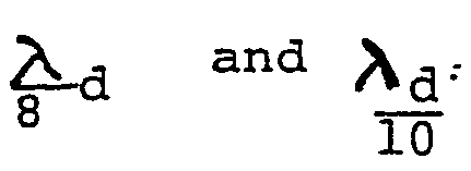
for periods from 10 to 12 seconds, the range of span would be between
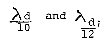
and for periods 12 to 15 seconds, the range would be between

[0031] For any wave periods and sea depths, xd may be found by iterative solution of the
function:
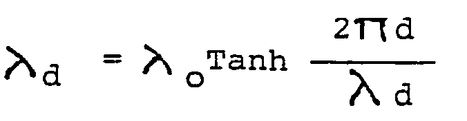
where λ
o is the wave length,

in very deep water, "g" is the gravitational acceleration constant 9.81 m/s
2, and "d" is the sea depth in meters.
[0032] Accordingly, for a design wave of period 14 seconds, for which Xd in a sea depth
30 meters may be found as 215.4 meters, the span "i" may be chosen from about 15.5
to 17 meters. Similarly if "T" is 10 seconds and "d" is 14 meters, the crest-to-crest
distance of a model wave is about 106.14 meters.
BALLASTING REQUIREMENTS
[0033] In order to evaluate the magnitude of peak thrust forces imposed by an incident large
wave, and specifically the peak composite horizontal force sustained by both the front
and back walls of the caisson, it is necessary to find the amplitude of the wave near
the front wall which combines the unaltered energy propagating toward the caisson
and the fraction reflected back by the structure. The amplitude may be expressed as:
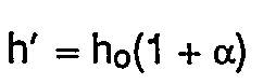
where h' is effective amplitude in meters, h
o is the amplitude with zero reflection, and a is a reflection coefficient ranging
from about 0.14 to about 0.18 for wall surfaces within a few meters of the datum plane,
and ranging upward to about 0.23 at the slab bottom. The coefficient for a rubble
base of porosity at least 35% may be taken as about 0.35.
[0034] The significance of the reflection coefficient is profound, as when a structure is
to be placed in a shallow sea to withstand large waves, where it would be in hazard
of undermining by vigorous bottom currents if the coefficient is not small. Solutions
for the following functions are used to obtain, at depths of interest, the values
of velocity "V" and of pressure "P".
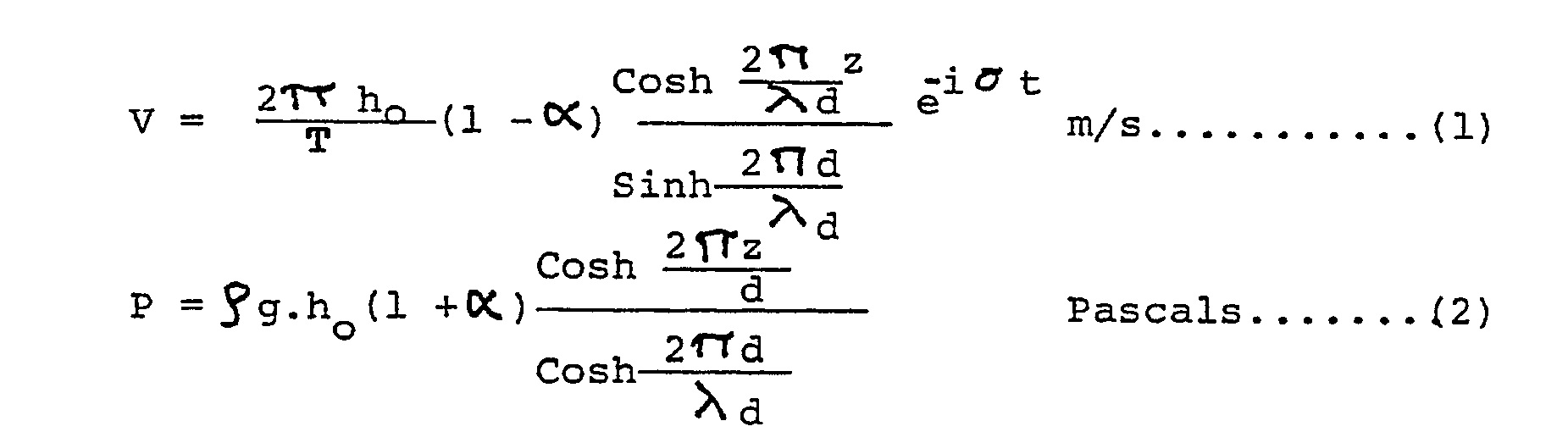
where:
z is the distance above seabed to the point investigated;
Cr is the wave phase at instant "t" and represents 2TT T
is 1026 kg per cubic meter of seawater.
[0035] The term (e
-iσt) expresses phase and propagation direction of the wave with time, the convention
herein being that the crest arrives at the front wall plane at instant t = 0.
[0036] Equations (1) and (2) should be used in conjunction with FIG. 3 which graphically
illustrates the change of wave celerity with depth for a range of periods of waves
most likely to propagate into shallow sea depths, and will aid in inferring how amplitude
h
o increases with reduction of crest-to-crest distance for a given rate of energy propagation
in deeper water, until the waveform becomes too steep and the wave collapses.
[0037] Referring next to FIGS. 4 and 5, there are shown successive phases of wave incidence
when the height of the sea 11' at the front wall is maximum in FIG. 4, and wherein
the water level in chamber 22 has increased in FIG. 5 a short time later from 27'
to its maximum elevation 27" and the sea height has decreased to 11". Accompanying
each drawing, outlines 28 and 29, and 28' and 29' are envelopes representing the variation
with height above slab bottom of dynamic pressure vectors such as 30 and 30', which
act respectively over the outer surface of front wall 20 and over the chamber side
of the back wall 21. The vector magnitudes may be computed from equations (1) and
(2) appearing hereinabove.
BALLASTING ARRANGEMENTS
[0038] Practical embodiments of the invention that place pervious ballast mass 31 in the
lower portion of chamber 22 are shown in FIGS. 2, 4 and 5. The mass extends upwardly
from slab bottom 17, to a level or nearly level upper surface 32 preferably slightly
lower than the lowest height of the sea when the trough of the design wave is at the
front wall. Ballast 31 of FIG. 2 comprises larger quarry stones, e.g. having roughly
uniform length, width and thickness dimensions and preferably of mass 2 to 4 tonnes
or more. The stones are placed into the standing caisson after it has been sited,
as by lowering the pieces by slings. The randomly-piled pervious mass should have
inter-fragment volume at least about 25%, up to about 40% of the bulk volume, so that
it offers low impedance to jets flowing from passages 25. Such ballasting represents
an economical solution where shipping and handling costs are low.
[0039] Where a supply of larger-size quarry stones of properties suitable for its use as
ballast may not be available locally, the embodiments of FIGS. 4 and 5 would be preferred.
In these, mass 31 is a concrete monolith provided with horizontal passages 33 extending
through the front wall 20, also through the ballast mass 31, and through the back
wall 21, there being no communication between the sea and the chamber through any
passages 33. However, free flow in all of the passages is possible whenever a hydraulic
head exists, depending on sea height and the datum plane surface 23. The axes 26'
of passages 33 coincide with the appropriate grid pattern of front wall openings as
previously discussed.
[0040] The grid pattern may be understood from front elevation view, FIG. 1 wherein lines
126 crossing at right angles include rows of horizontally spaced axes 26 and columns
of vertically spaced axes of one grid pattern, while lines 126' define squares of
the associated grid pattern. Where the desired ratio of passage cross-sectional area
to wall elevational area is 35%, the squares measure 1.97 meters when the passage
diameter is 0.93 meter.
[0041] The diameters of passages 33 are constant along their lengths, and may be identical
with the remainder of the front wall passages, i.e. those above the monolith, or they
may be made somewhat larger to decrease drag slightly, for example up to about 1.2
m.
[0042] The outlines 29 and 29' terminate at surface 32, where the magnitude of the dynamic
pressures acting on the back wall is significantly smaller than in the datum plane.
The outlines 28, 28' depict that horizontal pressure is at maximum at the moment of
incidence of the crest at the front wall plane, and hence the thrust force is also
maximum, while the pressure, and hence thrust force, are reduced at the time when
the motion of water in chamber 22 has elevated its height to a maximum adjacent the
back wall
[0043] Referring now also to FIG. 6, a force diagram is illustrated wherein the integral
value of pressure vectors 30, 30' over the areas of walls 20, 21 which sustain thrust
forces are combined to yield an aggregate force designated by vector F
H. The summation taken refers to the conditions of FIG. 5 since it has the highest
magnitude, but in each case a peak instantaneous value must be found by examining
a range of wave phases.
[0044] Caisson 10, as represented by slab bottom 17 exerts an aggregate downward force vector
Fv, and the rubble core surface 14 opposes the resultant R. Taking the coefficient
of friction for concrete on rubble as 0.6, and employing a safety factor for frictional
stability of at least 1.3, the possibility of sliding is avoided when:
Where it may be found, for example, that the peak value of F
H is about 1.35 x 10
6 Newtons per horizontal meter of length dimension of the caisson, the aggregate of
vertical forces must be about 2.93 x 10
6 Newtons. To determine how much ballast mass must be provided, one has to subtract
the immersed weight of the structure, the force exerted on surface 32 by the water
volume lying above the datum plane, and add the upward force due to hydraulic pressure
acting upwardly on the underside of slab bottom 17 including ledges 18 and 19. Depending
on the chosen height of rubble base surface 14, the weight of a segment of a caisson
formed of reinforced concrete which is virtually wholly immersed at the conditions
of FIG. 5 will be relatively a small part of the total of 2.93x10
6 Newtons. Therefore a depth of concrete ballast will be needed, for example 8 meters
or more, if the aggregate mineral has a density comparable to limestone. It will be
clear that use of higher density aggregates would be advantageous in decreasing the
height of mass 31, and to this end the mix may include as much steel fragments as
will be economically justified. Since the ballast mass is not subjected to loads affecting
the caisson structure, it need not be reinforced, and may be a much cheaper material
than is required for the walls and slab bottom.
[0045] The ballast mass 31 does not require to be in place when the caisson is towed to
its site, but a lesser portion 34 may be put into the caisson and the greater part
added after settling of the caisson on rubble base 13. The construction most simply
effected involves preforming tubular bodies 35 of length to extend through both caisson
walls, of highest-quality concrete as specified for duct lining, and casting the front
and back walls around their end portions while holding the bodies 35 horizontal and
in the required relative positions. Consequently the procedure is very similar to
the standard slip-forming of the walls, using pre-formed short ducts. As seen in FIG.
7, the emplacement of ballasting mass is by means of a trem- ie 36 which directs plastic
concrete mix between the tubular bodies, displacing sea water, until the desired height
has been cast.
[0046] As shown in FIG. 8, the pervious ballast mass 31 is also realized by casting a lower-cost
grade of concrete around tubular bodies which extend from anchored ends in the front
wall, almost to the back wall, but communicating at their ends 37 with the chamber.
Preferably, but not necessarily, the highest tubular bodies are made shorter than
the lowest tier, so that a passage 38 opening upwardly extends from the slab bottom
to the level of surface 32. The ballast is similarly cast as in FIG. 7 except that
suitable form- work 38A must be built to prevent ingress of concrete into the tubular
body ends 37 to form the passage 38, and to support the tubular bodies.
[0047] In FIGURE 9, cast tubular bodies 35 as shown in FIG. 8 occupy the same relative positions
as in FIG. 7, but have their ends sealed by plugs 39 so that no openings exist in
the back wall. The ballast mass is however made pervious by forming bodies 35 with
their cylindric surfaces extensively perforated by holes 40, so that water can interchange
from chamber to sea and vice versa by flowing into or out from the holes. To ensure
a sufficient weight of ballast, once the caisson is settled in position, sized rubble
fragments 41 are guided by flexible ducts (not shown) similarly to the guiding of
plastic concrete mix, to fill the spaces around the tubular bodies with pervious mineral.
The fragment sizes must be correlated with hole diameters and with the closest spacings
between outer surfaces of the bodies, so that material is not lost in the bodies,
and voids are absent.
[0048] While the method of ballasting in the foregoing embodiments is relatively economical
in employing either lower-cost concrete or rubble, the tubular bodies represent a
significant cost in that they must be made to stringent specifications of concrete,
and have an aggregate volume which is a substantial fraction of the final monolith
volume, or volume of tubular bodies and rubble pack. Where stone may be procured locally
in the form of graded fragments from about 0.4 meter to 1.3 meters the caisson 10
is simply made to be a receptacle for the required height of piled fragments. In such
embodiment, fragments 41 of only sizes larger than one meter are piled against the
inner side of front wall 20, while smaller fragments are used to fill the major part
of the space. Such packing scheme presents the lowest impedance to inflowing jets,
while affording excellent permeability both horizontally and vertically. The highly
pervious pack allows the pile to be extended rather further upward than would a monolith,
but in any case the height should not be above the lowest level of the sea adjacent
the front wall, i.e. at the trough phase as depicted in FIG. 1, 2 and 10.
[0049] As a means for further loading the caisson there may be placed on ledges 18, 19 and
extending into flanking rubble 16, stone fragments 41 of sizes such that the inflow
and outflow from passages 25 is not obstructed, as shown in FIG. 10.
[0050] The invention extends to caissons sited in shallow water, for example in a coastal
region where effects of wind, barometric variation, and tides may leave the slab bottom
barely wetted, or even out of the water, and at highest sea level the depth may be
only 13 to 15 meters. Since waves of periods from 10 seconds and greater may propagate
almost to the shore albeit at incipient collapse, the ballasting of caissons having
slab bottoms located on a thin rubble base whose upper surface 14 is disposed about
12 or 13 meters below datum plane ( taken as +14 meters), as shown in FIG. 12 is exceptionally
difficult. Since bottom pressures - and velocities are relatively large at seabed,
the risk of undermining is particularly great when only slightly increased reflection
results from use of internal ballasting. Since the structure weight when nearly wholly
immersed is even smaller in proportion to the required force e Fv specified for avoiding
sliding, the highest level to which ballast may be added will be close to the -7 meter
level, relative to datum plane. Unless a concrete of density higher than 2500 kg/m
3 is used, or additional ballasting arrangements are provided, the measures described
hereinabove may not ensure stability.
[0051] As shown in FIG. 11, additional ballast mass may be provided without significantly
increasing the impedance of front wall ducts 25, by fitting cast bodies 42 of square
plan form, of side dimensions conforming to the grid pattern of distribution of passages
25, on the outer surface 49 of the front wall 20, wherein these comprise openings
44 coaxial with the duct axes 26. The diameter of the opening is largest in a plane
remote from surface 43 and decreases smoothly to define a curved surface 45 as a body
of revolution, with diameter in the plane of surface 43 identical with the diameter
of passage 25. The axial extent may be a large fraction of one meter, for example
0.4 to about 0.7 meter. When bodies 42 are cast in concrete the faired surface 45
must be formed by casting at least a shell portion of highest grade concrete equivalent
to that used for passages 25. The remaining volume 46 may be a lower cost concrete
and advantageously may contain steel fragments. The shell may comprise a corrosion-resistant
metal, or the entire body may be formed of such metal to gain mass.
[0052] The bodies may be fixed in place during the building of the caisson, without impeding
flotation significantly, by sealing the openings 44 and gaining displacement volume.
A means of fixing the bodies when these are assembled after building uses pins 47
anchored in wall 20 as by concrete cast during building, the pins serving to position
and support the bodies by engaging holes in their planar sides 49 and being fixed
therein as by grout or other setting material.
[0053] The required additional ballast mass may be reduced by constructing caissons 100
as double-sided units, as shown in FIGS.12, 13, such form being particularly useful
as a combined groin/breakwater when arrayed generally at right angles to a shoreline
so that it provides sheltered lee areas 51, 52 depending on the sectors from which
waves may be expected. For example at a site where two lines of caissons are placed
on opposite sides of a navigable channel 53 in a river mouth or estuary, one side
may be likely to experience no large waves of period longer than about 7 seconds,
while the other side must resist waves up to 10 second period; the spans of chambers
22, 22' will accordingly be different thus determining the location of dividing wall
121.
[0054] The ballasting arrangement of FIG. 8 may be used, namely comprising tubular bodies
35 fixed in the front walls 20, 20', extending through the chambers to within one
meter to 1 meters of common back wall 121 to form a pair of upwardly-extending passageways
38, 38', and the upper surface of the monoliths cast around the tubes 35 is at a height
appropriate to the required ballasting. It should be noted that due to the much broadened
dimension of slab bottom 117 including short ledge portions, the uplift effect due
to bottom pressure of waves from either side will have a large magnitude, requiring
even greater ballasting.
[0055] To avoid accretion of sand at a side of the breakwater a tier of small diameter holes
54 may be provided in the lower part of wall 121, to allow migration of entrained
sand particles through both front walls, hence correcting a difficulty experienced
with known groins.
[0056] In certain installations it may be desirable to increase greatly the weight of the
structure with virtually no impediment to horizontal and vertical motions of water
in the chamber, thereby assuring virtually no increase of reflection coefficient.
Since one cubic meter of steel in seawater exerts downward force about 68,000 Newtons
whereas the same volume of concrete produces a gravity force of only about 15,000
Newtons, the use of steel will allow much greater porosity of the ballast mass and
a lower height in the chamber. Only lower grades of steel are required since no loads
other than their own weight are carried. FIG. 14 shows a section in elevation wherein
dashed circles 55 represent cylindric surfaces of phantom tubes coaxial with the axes
26 of front wall passages 25 and of identical diameter, and represent generally the
outline of jets flowing from such passages into the chamber. For example, where the
passage distribution pattern as shown arranges a first set of passage axis positions
at the corners of squares of a grid and arranges axis positions of a second set at
the intersections of diagonals of squares of such grid, the disposition of metal ballast
is most effectively arranged as tiers of horizontally spaced slabs 56 and 56' as shown.
The thickness dimension of such slabs may be from 0.2 to 0.35 meter, the slabs extending
horizontally, for example coextensive with the chamber span. The width dimension extends
vertically, and may be about 1.05 meter or about 1.25 meters, depending on the tier.
[0057] As shown, the wider slabs occupy positions with their wide faces 57 tangent with
the phantom cylinder 55 at the ends of a horizontal diameter 58, while the other slabs
56' have their narrow faces 59 tangent with the cylinders 55 at the ends of a vertical
diameter 59. The set of slabs is supported by vertical framing members 60 and horizontal
beams 61, arranged as racks disposed generally adjacent the interior surfaces of walls
20 and 21.
[0058] All or part of the concrete or rubble ballast referred to hereinbefore may be replaced
wholly or partially with cast, fragmented, scrap or other metal bodies, e.g. low cost
steel bodies.
1. A breakwater comprising a line of caissons (10) each having an upright front wall
(20) extensively perforated by regularly distributed transverse passages (25), and
second wall (21) spaced from the front wall to form chamber (22) between the walls,
and having a slab bottom (17), a base (13) of pervious rubble piled on seabed and
having a levelled upper surface, said slab bottom resting on said rubble pile and
characterised in that, said upper surface is disposed at a depth below mean sea level
substantially less than four times the amplitude of the largest predicted wave; in
that the weight of the caisson itself is insufficient to anchor the caisson against
sliding by friction of said slab bottom relative to said upper surface; in that the
caisson carries a ballast mass (31) disposed in said chamber extending upward from
the slab bottom to a height below the lowest height of the sea when the trough of
said wave is at the front wall, said mass adding sufficient weight to ensure that
the ratio of maximum horizontal thrust force of said wave to net downward vertical
force including the weight of said mass is below 0.46; and in that said mass is pervious
to seawater flowing through said front wall.
2. A breakwater comprising a base (13) of pervious rubble piled on seabed and having
a levelled upper surface, a line of unitary concrete caissons (10) each having a pair
of upright front walls (20, 20') extensively perforated by regularly-distributed transverse
passages (25) and spaced apart, an intermediate wall (121) parallel with said front
walls and dividing the space between them into two chambers (22), a slab bottom (17)
integrally joined with said upright walls, and resting upon said upper surface, and
characterised in that said upper surface lies at a depth below means sea level less
than four times the amplitude of the largest predicted wave that may impinge either
front wall, and wherein the weight of the caisson itself is insufficient to anchor
the caisson against sliding by friction of said slab bottom relative to said upper
surface, wherein the caisson carries ballast masses (31) disposed in each of said
chambers extending upward from the associated portion of the slab bottom to a height
below mean sea level which is at least as large as the amplitude of the said wave,
said masses adding sufficient weight to ensure that the ratio of maximum horizontal
thrust force of said wave to net downward vertical force including the weight of said
masses is below 0.46, and said masses are pervious to seawater flowing through an
associated front wall.
3. A breakwater as set forth in Claim 1 or 2 wherein said distributed passages (25)
in the or each front wall are horizontal ducts of diameter between about 0.9 and 1.2
meters and the aggregate cross-sectional area of the passages is about 35% of the
elevational area of the wall, and wherein the ballast mass (31) comprises randomly-filed
rubble and/or metal fragments providing inter-fragment volume at least about 25% of
the bulk volume occupied by the ballast, the size of those fragments emplaced adjacent
said front wall being larger than the transverse dimension of said ducts.
4. A breakwater as set forth in Claim 1 wherein said ballast mass comprises, in part,
cylindric pipes (33, 35) extending horizontally in the lower part of said chamber
normally of said front wall and having their one ends fixed in said front wall and
opening to the sea, said pipe openings occupying positions in the same distribution
pattern as said passage openings, said pipes having their other ends extending through
said second wall and opening to the sheltered water outside said second wall.
5. A breakwater as set forth in Claim 1 wherein said ballast mass comprises, in part,
cylindric pipes extending horizontally in the lower portion of said chamber normally
of said front wall and having their one ends fixed in said front wall and opening
to the sea, said pipe openings occupying positions in the same distribution pattern
as said passage openings, the other ends of said pipes terminating in said chamber
and spaced adjacently said second wall to define with the second wall an upwardly
extending unobstructed passage, and wherein the remainder of said ballast mass comprises
a monolith having an upwardly-extending wall spaced inwardly from said second wall,
and said wall presenting openings of said other ends to said passage.
6. A breakwater as set forth in Claim 1 wherein said ballast mass comprises, in part,
cylindric pipes extending horizontally in the lower portion of said chamber normally
of said front wall and having their one ends fixed in said front wall and opening
to the sea with said openings in the same distribution pattern as the passages of
said front wall, the other ends of said pipes being fixed in said second wall and
being closed, said pipes being extensively perforated by ports opening (40) through
their cylindric surfaces and allowing interchange of water between the sea and said
chamber, and wherein the remainder of said ballast mass comprises a pervious rubble
pack emplaced in said chamber surrounding said pipes, said port openings having cross-sectional
dimensions fractionally smaller than the least distance between adjacent pipe surfaces
and said rubble sizes being in a range allowing free emplacement between said pipes
but preventing their ingress into said pipes.
7. A breakwater as set forth in Claim 1 wherein said ballast mass comprises, in part,
cylindric pipes extending horizontally in the lower portion of said chamber normally
of said front wall and having their one ends fixed in said front wall and opening
to the sea, said pipe openings occupying positions in the same distribution pattern
as said passages of said front wall, said pipes terminating in said chamber with their
other ends spaced adjacent said second wall, a wall rising from the slab bottom supporting
said other ends and defining with said second wall an upwardly open passageway, said
pipes being extensively perforated by ports opening through their cylindric surfaces
and allowing interchange of water between the chamber and pipe interiors, and wherein
the remainder of said ballast mass comprises a pervious rubble pack emplaced in said
chamber surrounding aid pipes, said ports having cross-sectional dimensions fractionally
smaller than the least distance between adjacent pipe surfaces and said rubble sizes
being in a range allowing free emplacement between said pipes but preventing their
ingress into said pipes.
8. A breakwater as set forth in Claim 1, 4, 5, 6 or 7 wherein the distance between
said front and second walls is correlated with the wavelength of the incident wave
of largest predicted amplitude at the site depth, such that for waves of periods about
7 to 10 seconds the span is from 0.10 to 0.125 times the wavelength, for waves of
periods 10 to 12 seconds the span is from 0.1 to about 0.0833 tims the wavelength,
and for periods 12 to 15 seconds the span is about 0.0833 to about 0.0667 times the
wavelength.
9. A breakwater as set forth in Claim 2 wherein said intermediate wall includes at
least one tier of holes opening (54) near said slab bottom into each chamber, the
cross-sectional area of each hole being a small fraction of the area of a passage
in said front walls, whereby mineral particles entrained in a sea in which said wave
is propagating may pass through both said front walls.
10. A breakwater as set forth in Claim 2 or 9 wherein said line of caissons extends
generally at right angles to a shoreline as a groin and said rubble base is of increasing
thickness with sea depth.
11. A breakwater as set forth in Claim 2, 9 or 10 wherein two lines of caissons extend
from a shoreline adjacent the mouth of a river flowing into the sea and the lines
are sited on opposite sides of a navigable channel (53) along the river bed, and wherein
the chamber adjacent that front wall which is exposed to the larger of a pair of predicted
largest-amplitude waves likely to be incident from respective sectors facing the said
front walls has a span larger than the span of the other chamber.
12. A breakwater as set forth in Claim 2, 9, 10 or 11 wherein said span dimensions
are correlated with the wavelength for the depth of sea at highest mean sea level
of the site and the chamber span is from 0.10 to 0.125 times the wavelength for waves
of periods about 7 to about 10 seconds, and is from about 0.10 to about 0.0833 times
the wavelength of waves of periods from about 10 to about 12 seconds, and is from
about 0.0833 to about 0.0667 times the wavelength of waves of periods about 12 to
about 15 seconds.
13. A breakwater as set forth in Claim 2, 9, 10, 11 or 12 wherein said ballast mass
comprises, in part, cylindric pipes extending horizontally in the lower portion of
each said chamber normally of the front wall and having their one ends integrally
fixed in said front wall and opening to the sea with said openings in the same distribution
pattern as the passages of said front wall, said pipes terminating in the chamber
with their other ends spaced adjacent said intermediate wall, a wall rising from the
slab bottom in each chamber supporting said other ends and defining with said intermediate
wall an upwardly-open passageway communicating with the interiors of said pipes, and
wherein the remainder of said ballast mass comprises ballast material occupying at
least a major volume proportion of the space between said pipes.
14. A breakwater as set forth in Claim 4, 5 or 13 wherein the remainder of said ballast
mass comprises concrete solidified around said pipes.
15. A breakwater as set forth in Claim 14 wherein the concrete includes a significant
proportion of metal fragments admixed as aggregate, and the weight of said mass is
preferably sufficient to make said ratio below 0.4.
16. A breakwater as set forth in Claim 4, 5 or 13 wherein the remainder of said ballast
mass comprises rubble and/or metal packed around said pipes.
17. A breakwater as set forth in Claim 4, 5, 6, 7, 13, 14 or 15 wherein said pipes
are thick-walled tubes preformed by spin casting, and their ends are fixed in the
respective upright walls by slip-form casting of the walls about said ends.
18. A breakwater as set forth in Claim 16 wherein said pipes are extensively perforated
by ports opening through their cylindric surfaces, said ports having cross-sectional
dimensions fractionally smaller than the least distance between adjacent pipe surfaces
and said rubble sizes being in a range allowing free emplavement between said pipes
but preventing their ingress into said pipes.
19. A breakwater as set forth in Claim 1 or 2 wherein said front wall (20) has a substantially
planar exterior surface and said transverse passages (25) comprise cylindric holes
(33) having axes normal to said planar surface, and said front wall carries augmenting
ballast bodies (42) having one planar side allowing flush mounting of said bodies
against said exterior surface (49), means (47, 48) fixing each of said bodies to said
front wall, said bodies comprising a centrally-apertured square of side dimension
such that said bodies may be mounted in the same distribution pattern as said passages,
wherein the aperture diameter in the plane of said exterior surface is identical with
the passage diameter and the aperture surface is a body of revolution (45) about said
axis characterised by gradual smooth increase of diameter in the axial direction outwardly
from said front wall to about 140% of the passage diameter within a distance about
one-half of the passage diameter.
20. A breakwater as set forth in Claim 19 wherein said body is formed by casting concrete.
21. A breakwater as set forth in Claim 19 wherein said body includes a shell shaped
to provide said aperture surface and formed of corrosion-resistant metal and the remainder
of the body is concrete.
22. A breakwater as set forth in Claim 1 or Claim 2 wherein said passages are distributed
over said front wall area as a first set of passages having axes disposed at the corners
of squares of a first grid of horizontally and vertically spaced passages, and as
a second set of passages having axes disposed at the intersection of diagonals of
squares of said first grid and forming a second grid, and wherein the ballast mass
comprises tiers of horizontally-spaced metal slabs (56, 56') of thickness about 0.2
to 0.35 meter, said slabs being oriented with their width dimension vertical, and
having horizontal length substantially coextensive with the chamber span, the slabs
of one set of tiers being positioned with their wide faces approximately tangent at
opposite ends of a horizontal diameter of a phantom cylindric surface coaxial with
each passage of one grid set of passages and of the same diameter as said passages,
and the slabs of a second set of tiers having their narrow faces tangent with said
surface at opposite ends of a vertical diameter, said ballast mass including support
frameworks extending upwardly from said slab bottom, the slabs not obstructing flow
from any passage.
23. A breakwater as set forth in Claim 22 wherein said support frameworks comprise
at least two grids each formed of vertical and horizontal members (60, 61), said members
being roughly tangent with said phantom cylindric surface at the ends of a horizontal
and a vertical diameter (58, 59), respectively, wherein the vertical members stand
upon said slab bottom and include one group closely adjacent the wall opposite to
the front wall.
24. A breakwater as set forth in any preceding Claim, wherein said upper surface of
said base is at a depth between about 2.6 and 3.4 times said amplitude.
25. A breakwater as set forth in any preceding claim wherein said upper surface is
at least about 0.6 meters above seabed.
26. A breakwater as set forth in any preceding claim wherein said slab bottom and
said front and back walls are connected integrally with upright transverse bracing
walls spaced along the horizontal length of the caisson, said bracing walls having
about 45% of their elevational areas comprised of openings, and wherein said ballast
mass occupies said openings within the vertical extent of said mass.
27. A breakwater as set forth in any preceding claim wherein said slab bottom and
said front and back walls are connected integrally with upright transverse apertured
bracing walls (24, 24') spaced along the horizontal extent of the caisson, and said
slab bottom includes horizontal ledges (18, 19) extending respectively beyond the
front and back walls and resting on said rubble base, and said bracing walls in- dude
integral outward extensions joined with said ledges and with the exterior surfaces
of said front and back walls, said extensions rising less than about 10 meters above
said rubble base, and wherein rubble fragments of sizes greater than the cross-sectional
dimensions of said passages are piled upon said ledges and said rubble base.
1. Wellenbrecher, bestehend aus einer Reihe von Caissons (10), von denen jeder eine
aufrecht stehende Vorderwand (20), die weitgehend durch regelmäßig verteilte Queröffnungen
(25) perforiert ist, eine zweite Wand (21), die zur Bildung einer Kammer (22) zwischen
den Wänden im Abstand von der Vorderwand angeordnet ist, und einen Plattenboden (17)
aufweist, wobei eine Basis (13) aus auf dem Meeresboden aufgeschichtetem, durchlässigem
Geröll vorgesehen ist, die eine planierte Oberseite aufweist und auf der der Caissonsboden
ruht, dadurch gekennzeichnet, daß diese Oberseite in einer Tiefe unterhalb des Meeresspiegels
liegt, die im wesentlichen kleiner ist als das Vierfache der Amplitude der höchsten
vorhersehbaren Welle, daß das Gewicht des Caissons selbst unzureichend ist, um den
Caisson gegen ein Gleiten durch Reibung des Plattenbodens relativ zu dieser Oberseite
zu sichern, daß der Caisson in der Kammer eine Ballastmasse (31) aufnimmt, die von
dem Plattenboden bis zur einer Höhe unterhalb der höchsten Höhe des Meeresspiegels
reicht, wenn sich ein Tal dieser Welle an der Vorderwand befindet, wobei diese Masse
ein ausreichendes, zusätzliches Gewicht darstellt, um sicherzustellen, daß das Verhältnis
der maximalen horizontalen Schubkraft dieser Welle zu der nach unten gerichteten Nettovertikalkraft
einschließlich des Gewichtes dieser Masse unter 0,46 liegt, und daß diese Masse für
das durch die Vorderwand strömende Seewasser durchlässig ist.
2. Wellenbrecher mit einer eine planierte Oberseite aufweisenden Basis (13) aus auf
dem Meeresboden aufgeschichtetem, durchlässigem Geröll, einer Reihe aus Einheits-Betoncaissons
(10), von denen jeder ein Paar von aufrecht stehenden Vorderwänden (20, 20), die im
Abstand voneinander liegen und in wesentlichem Umfang durch gleichmäßig verteilte
Queröffnungen (25) perforiert sind, eine zu diesen Vorderwänden parallele Zwischenwand
(121), die den Raum zwischen diesen in zwei Kammern (22) unterteilt, und einen Plattenboden
(17) aufweist, der mit diesen aufrechten Wänden fest verbunden ist und der auf dieser
Oberseite ruht, dadurch gekennzeichnet, daß die Oberseite in einer Teife unter dem
Meeresspiegel liegt, die kleiner ist als das Vierfache der Amplitude der höchsten,
vorhersehbaren Welle, die gegen eine der beiden Vorderwände auftrifft, wobei das Gewicht
des Caissons selbst nicht ausreicht, um den Caisson gegen ein Gleiten des Plattenbodens
relativ zu dieser Oberseite zu verankern, wobei der Caisson innerhalb jeder dieser
Kammern untergebrachte Ballastmassen (31) aufnimmt, die von dem jeweiligen Abschnitt
des Plattenbodens bis zu einer Höhe unterhalb des mittleren Meeresspiegels reichen,
die mindestens genauso groß ist wie die Amplitude dieser Welle, wobei diese Massen
ein Zusatzgewicht darstellen, welches ausreicht, um sicherzustellen, daß das Verhältnis
der maximalen, horizontalen Schubkraft dieser Welle zu der nach unten gerichteten
Nettovertikalkraft einschließlich des Gewichtes dieser Massen geringer als 0,46 ist,
und daß diese Massen für das durch eine zugeordnete Vorderwand strömende Seewasser
durchlässig sind.
3. Wellenbrecher nach Anspruch 1 oder 2, bei dem die in jeder Vorderwand angeordneten
Öffnungen (25) horizontale Kanäle mit einem Durchmesser zwischen etwa 0,9 und 1,2
m sind, wobei die Gesamtquerschnittsfläche dieser Öffnungen etwa 35% der Horizontalprojektion
dieser Wand ausmachen, und wobei die Ballastmasse willkürlich aufgeschichtete Geröll-
oder Metallfragmente mit einem Zwischenraumvolumen von mindestens etwa 25% des von
dem Ballast eingenommenen Raumvolumens ausmachen, wobei die Größe dieser an diese
Vorderwand angrenzenden Fragmente größer ist als die Querschnittsdimension dieser
Kanäle.
4. Wellenbrecher nach Anspruch 1, bei dem die Ballastmasse teilweise zylindrische
Rohre (33, 35) umfasst, die in dem unteren Abschnitt dieser Kammer horizontal und
normal zu dieser Vorderwand liegen und mit ihren einen Enden in dieser Vorderwand
befestigt und zur See hin offen sind, wobei diese Rohröffnungen Lagen in dem gleichen
Verteilungsmuster wie die Kanalöffnungen einnehmen, wobei diese Rohre sich mit ihren
anderen Enden durch diese zweite Wand erstecken und sich zu der abgeschirmten Wasserseite
außerhalb dieser zweiten Wand öffnen.
5. Wellenbrecher nach Anspruch 1, bei dem diese Ballastmasse teilweise zylindrische
Rohre umfasst, die in dem unteren Abschnitt dieser Kammer horizontal und normal zu
dieser Vorderwand liegen und mit ihren einen Enden in dieser Vorwand befestigt und
zur See hin offen sind, wobei diese Rohröffnungen Lagen in dem gleichen Verteilungsmuster
wie die Kanalöffnugnen einnehmen, während die anderen Enden dieser Rohre in dieser
Kammer im Abstand von dieser zweiten Wand enden, um mit der zweiten Wand einen nach
oben gerichteten, hindernisfreien Kanal zu begrenzen, wobei die restliche Ballastmasse
aus einem Monolith besteht, der eine sich nach oben erstreckende Wand aufweist, die
nach innen im Abstand von dieser zweiten Wand liegt und in diesen Kanal mündende Öffnungen
dieser anderen Enden aufweist.
6. Wellenbrecher nach Anspruch 1, bei dem diese Ballastmasse teilweise zylindrische
Rohre umfasst, die in dem unteren Abschnitt dieser Kammer horizontal und normal zu
dieser Vorderwand liegen und mit ihren einen Enden in dieser Vorderwand befestigt
und zur See hin offen sind, wobei diese Öffnungen in dem gleichen Verteilungsmuster
wie die Kanäle dieser Vorderwand angeordnet sind, während die anderen Enden dieser
Rohre in dieser zweiten Wand befestigt und verschlossen sind, wobei diese Rohre in
wesentlichem Umfang durch Öffnungen (40) perforiert sind, die im Bereich ihrer Zylinderflächen
liegen und einen Austausch von Wasser zwischen der See und dieser Kammer ermöglichen,
wobei die restliche Ballastmasse eine durchlässige Geröllpackung umfasst, die diese
Rohre umgebend in dieser Kammer untergebracht ist, wobei die Öffnungen Querschnittsdimensionen
aufweisen, die fraktionell kleiner sind als der geringste Abstand zwischen benachbarten
Rohroberflächen, wobei die Geröllstücke eine Größe in einem Bereich haben, die ihre
freie Bewegung zwischen diesen Rohren ermöglicht, jedoch ihren Eintritt in diese Rohre
verhindert.
7. Wellenbrecher nach Anspruch 1, bei dem diese Ballastmasse teilweise zylindrische
Rohre umfasst, die in dem unteren Bereich dieser Kammer horizontal und normal zu dieser
Vorderwand liegen und mit ihren einen Enden in dieser Vorderwand befestigt und zur
See hin offen sind, wobei diese Rohröffnungen Lagen in dem gleichen Verteilungsmuster
wie die Kanalöffnungen dieser Vorderwand einnehmen, wobei diese Rohre in der Kammer
mit ihren anderen Enden im Abstand von dieser zweiten Wand enden, wobei auf dem Plattenboden
eine Wand aufgerichtet ist, die diese anderen Enden abstützt und mit dieser zweiten
Wand einen nach oben offenen Kanal begrenzt, wobei diese Rohre in beträchtlichem Umfang
mit Öffnungen perforiert ist, die durch ihre Zylinderflächen hindurch offen sind und
einen Austausch von Wasser zwischen der Kammer und den Rohrinnenräumen ermöglichen,
wobei die restliche Ballastmasse eine durchlässige Geröllpackung umfasst, die die
Rohre umgebend in dieser Kammer untergebracht ist, wobei diese Öffnungen Querschnittdimensionen
haben, die fraktionell kleiner sind als der geringste Abstand zwischen benachbarten
Rohroberseiten, und wobei die Geröllstücke Größen in einem Bereich haben, die ihre
freie Verlagerung zwischen diesen Rohren ermöglicht, jedoch ihren Eintritt in diese
Rohre verhindem.
8. Wellenbrecher nach Anspruch 1, 4, 5, 6 oder 7, bei dem der Abstand zwischen der
Vorderwand und der zweiten Wand abgestimmt ist auf die Wellenlänge der auftreffende
Welle mit der größten vorhersehbaren Amplitude an der Seitenhöhe, derart, daß für
Wellen mit Perioden von 7 bis 10 sek. der Abstand das 0,10- bis 0,125-fache der Wellenlänge,
für Wellen mit Perioden von 10 bis 12 sek. der Abstand das 0,1- bis etwa 0,0833-fache
der Wellenlänge, und für Perioden von 12 bis 15 sek. der Abstand etwa das 0,0833-
bis etwa 0,0667-fache der Wellenlänge ausmacht.
9. Wellenbrecher nach Anspruch 2, bei dem diese Zwischenwand mindestens eine Reihe
von Öffnungen (54) aufweist, die in der Nähe des Plattenbodens zu jeder Kammer hin
offen sind, wobei die Querschnittsfläche jeder Öffnung eine kleine Fraktion der Fläche
einer Öffnung in dieser Vorderwand ausmacht, so daß Mineralpartikel, die in einer
See mitgerissen werden, in der die Welle sich fortpflanzt, durch beide Vorderwände
hindurchtreten können.
10. Wellenbrecher nach Anspruch 2 oder 9, bei dem die Caissonreihe sich im wesentlichen
rechtwinkelig zu einer Küstenlinie als eine Buhne erstreckt, wobei diese Geröllbasis
in Abhängigkeit von der Meerestiefe eine anwachsende Dicke hat.
11. Wellenbrecher nach Anspruch 2, 9 oder 10, bei dem sich zwei Caissonreihen von
einer Uferlinie angrenzend an die Mündung eines in die See fließenden Flusses erstrecken,
wobei die Reihen sich auf gegenüberliegenden Seiten eines schiffbaren Kanals (53)
entlang des Flussbettes erstrecken, und wobei die Kammer, die an die Vorderwand angrenzt,
die der größeren von einem Paar von vorhersehbaren Wellen mit größten Amplituden ausgesetzt
ist, die wahrscheinlich von entsprechenden Sektoren einfallen, die diesen Vorderwänden
gegenüberliegen, eine größere lichte Weite hat als die lichte Weite der anderen Kammer.
12. Wellenbrecher nach Anspruch 2, 9, 10 oder 11, bei dem diese Weitendimensionen
abgestimmt sind auf die Wellenlänge für die Seetiefe mit dem höchsten mittlern Meeresniveau
an dieser Seite, wobei die lichte Weite der Kammer das 0,10- bis 0,125-fache der Wellenlänge
für Wellen mit Perioden von etwa 7 bis 10 sek., etwa das 0,10- bis etwa 0,0833-fache
der Wellenlänge von Wellen mit Perioden von etwa 10 bis etwa 12 sek., und etwa das
0,0833- bis etwa 0,0667-fache der Wellenlänge von Wellen mit Perioden von etwa 12
bis etwa 15 sek. ausmacht.
13. Wellenbrecher nach Anspruch 2, 9, 10, 11 oder 12, bei dem diese Ballastmasse teilweise
zylindrische Rohre umfasst, die in dem unteren Abschnitt jede dieser Kammern horizontal
und normal zu der Vorderwand befestigt sind, wobei ihre einen Enden fest in dieser
Vorderwand befestigt und zur See hin offen sind, wobei ihre Rohröffnungen in dem gleichen
Verteilungsmuster wie die Kanalöffnungen dieser Vorderwand liegen, wobei diese Rohre
in der Kammer mit ihren anderen Enden im Abstand von dieser Zwischenwand enden, wobei
auf dem Plattenboden in jeder Kammer eine Wand zur Abstützung der anderen Rohrenden
aufgerichtet ist, die mit dieser Zwischenwand einen nach oben hin offenen Kanal begrenzen,
der mit dem Inneren dieser Rohre in Verbindung steht, und wobei die restliche Ballastmasse
ein Ballastmaterial umfasst, welches mindestens einen größeren Volumenanteil des Zwischenraumes
zwischen diesen Rohren einnimmt.
14. Wellenbrecher nach Anspruch 4, 5 oder 13, bei dem die restliche Ballastmasse Beton
umfasst, der um die Rohre herum verfestigt ist.
15. Wellenbrecher nach Anspruch 14, bei dem der Beton einen wesentlichen Anteil als
Zuschlagstoff zugemischter Metallfragemente enthält, wobei das Gewicht dieser Masse
vorzugweise ausreicht, um dieses Verhältnis auf einen Wert unter 0,4 einzustellen.
16. Wellenbrecher nach Anspruch 4, 5 oder 13, bei dem die restliche Ballastmasse Geröll
und/oder Metall umfasst, das um diese Rohre geschichtet ist.
17. Wellenbrecher nach Anspruch 4, 5, 6, 7, 13, 14 oder 15, bei dem diese Rohre dickwandige,
im Schleuderguß hergestellte Rohre sind, deren Enden in den zugeordneten, aufrechten
Wänden durch Gleitschalungsguß der Wände um diese Enden befestigt sind.
18. Wellenbrecher nach Anspruch 16, bei dem diese Rohre in beträchtlichem Umfang mit
Öffnungen perforiert sind, die sich durch ihre zylinden Wände erstrecken, wobei diese
Öffnungen Querschnittsdimensionen haben, die fraktionell kleiner sind als der geringste
Abstand zwischen benachbarten Rohroberflächen, und wobei die Geröllstücke Größen in
einem Bereich haben, der ihre freie Verlagerung zwischen diesen Rohren ermöglicht,
jedoch ihren Eintritt in diese Rohre verhindert.
19. Wellenbrecher nach Anspruch 1 oder 2, bei dem diese Vorderwand (20) eine im wesentlichen
planare Außenseite und die Queröffnungen zylindrische Löcher umfassen, deren Achsen
normal zu dieser planaren Seite liegen, wobei diese Vorderwand gewichtsvergrößernde
Ballastkörper (42) mit einer planaren Seitenfläche enthält, die ein bündiges Anbringen
dieser Körper gegen diese Außenfläche (49) ermöglichen, wobei Einrichtungen (47, 48)
zur Befestigung dieser Körper an dieser Vorderwand vorgesehen sind, wobei diese Körper
ein zentral geöffnetes Rechteck mit einer solchen Seitendimension haben, daß diese
Körper in dem gleichen Verteilungsmuster wie diese Wandöffnungen montiert werden können,
wobei der Öffnungdurchmesser in der Ebene dieser Außenfläche identisch ist mit dem
Wandöffnungsdurchmesser, wobei die Öffnungsfläche ein Rotationskörper (45) um diese
Achse ist, der charakterisiert ist durch ein graduelles Anwachsen des Durchmessers
in Achsialrichtung nach außen von dieser Vorderwand auf etwa 140% des Wandöffnungsdurchmesser
innerhalb eines Abstandes von etwa einer Hälfte des Wandöffnungsdurchmessers.
20. Wellenbrecher nach Anspruch 19 dadurch gekennzeichnet, daß dieser Körper aus Betonguß
hergestellt ist.
21. Wellenbrecher nach 19, dadurch gekennzeichnet, daß dieser Körper ein zu Bildung
dieser Öffnungsfläche geeignetes Gehäuse aus korrosionsbeständigem Metall umfasst,
während der restliche Teil des Körpers aus Beton besteht.
22. Wellenbrecher nach 1 oder 2, bei dem diese Wandöffnungen über diese Vorderwandfläche
als ein erster Satz Öffnungen, deren Achsen an den Eckpunkten von Rechtecken eines
ersten Gitters aus horizontal und vertikal im Abstand voneinander liegenden Öffnungen
liegen, und als ein zweiter Satz von Öffnungen verteilt sind, deren Achsen in den
Schnittpunkten der Quadratdiagonalen des ersten Gitters liegen und ein zweites Gitter
bilden, wobei die Ballastmasse eine Reihe von horizontal im Abstand voneinander angeordneten
Metallplatten (56, 56) mit einer Dicke von etwa 0,2 bis 0,35 m umfasst, wobei diese
Platten mit ihren Breitendimensionen vertikal ausgerichtet sind und eine horizontale
Länge im wesentlichen mit der gleichen Ausdehnung wie die lichte Kammerweite haben,
wobei die Platten eines Satzes von Reihen mit ihren Breitflächen in etwa tangential
an gegenüberliegenden Enden eines horizontalen Durchmessers einer Phantomzylinderfläche,
die koachsial zu jeder Wandöffnung eines Gittersatzes von Öffnungen mit dem gleichen
Durchmesser wie diese Öffnungen positioniert sind, liegen, während die Platten eines
zweiten Reihensatzes ihre Schmalseiten tangential zu dieser Fläche an entgegengesetzten
Enden eines vertikalen Durchmessers haben, wobei diese Ballastmasse ein sich von dem
Plattenboden nach oben erstreckendes Stützgerüst umfasst und die Platten die Strömung
von jeder der Wandöffnungen aus nicht behindern.
23. Wellenbrecher nach Anspruch 22, bei dem das Stützgerüst mindestens zwei Gitter
umfasst, von denen jedes aus vertikalen und horizontalen Gliedern (60, 61) gebildet
ist, die ungefähr tangential zu der Phantomzylinderfläche an den Enden eines horizontalen
bzw. eines vertikalen Durchmessers (58, 59) liegen, wobei die vertikalen Elemente
auf dem Plattenboden stehen und eine Gruppe dicht bei der der Vorderwand gegenüberliegenden
Wand umfassen.
24. Wellenbrecher nach jedem vorhergehenden Anspruch, bei dem die Oberseite der Basis
in eine Tiefe zwischen etwa dem 2,6- und 3,4-fachen dieser Amplitude liegt.
25. Wellenbrecher nach jedem der vorhergehenden Ansprüche, bei dem diese Oberseite
mindestens etwa 0,6 m über dem Meeresboden liegt.
26. Wellenbrecher nach jedem vorhergehenden Anspruch, bei dem der Plattenboden und
die Vorder-und Rückwände fest durch aufrechtstehende Versteifungswände miteinander
verbunden sind, die über die horizontale Länge des Caissons im Abstand voneinander
liegen, wobei etwa 45% der Horizontalprojektion dieser Versteifungswände aus Öffnungen
besteht, wobei diese Ballastmasse diese Öffnungen innerhalb der vertikalen Erstreckung
dieser Masse einnimmt.
27. Wellenbrecher nach jedem vorhergehenden Anspruch, bei dem der Plattenboden und
die Vorder-und Rückwände fest durch aufrechtstehende, und mit (querliegenden Öffnungen
versehene Versteifungswände (2424-) miteinander verbunden sind, die entlang der horizontalen
Länge des Caissons angeordnet sind, wobei der Plattenboden gegenüber den Vorder- und
Rückwänden vorspringende Flansche (18, 19) aufweist, die auf der Basis aufliegen,
wobei die Versteifungswände integrale, nach außen gerichtete Vorsprünge umfassen,
die mit diesen Flanschen und mit den Außenflächen der Vorder- und Rückwände verbunden
sind, wobei diese Vorsprünge sich weniger als etwa 10 m über der Basis erstrecken,
und wobei auf diese Flansche und die Geröllbasis Geröllfragmente aufgeschichtet sind,
die größer sind als die Querschnittsdimensionen der Wandöffnungen.
1. Brise-lames comprenant une ligne de caissons (10) comportant chacun une paroi avant
verticale (20) fortement perforée par des passages transversaux (25) répartis régulièrement,
et une seconde paroi (21) espacée de la paroi avant de façon à former une chambre
(22) entre les parois, et comportant une dalle de fond (17), une base (13), en enrochement
perméable accumulé sur le fond de la mer et comportant une surface supérieure nivelée,
ladite dalle de fond reposant sur ladite accumulation d'enrochement, et caractérisé
en ce que ladite surface supérieure est disposée à une profondeur en dessous du niveau
moyen de la mer qui est sensiblement inférieure à quatre fois l'amplitude de la plus
grosse vague prévue; en ce que le poids du caisson proprement dit est insuffisant
pour ancrer le caisson en l'empêchant de glisser par frottement de ladite dalle de
fond par rapport à ladite surface supérieure; en ce que le caisson porte une masse
de ballast (31) disposée dans ladite chambre et s'étendant vers le haut à partir de
ladite dalle de fond jusqu'à une hauteur inférieure à la hauteur minimale de la mer
lorsque le creux de ladite vague est situé sur la paroi avant, ladite masse ajoutant
un poids suffisant pour faire en sorte que le rapport entre la force de poussée horizontale
maximale de ladite vague et de la force verticale résultante dirigée vers le bas et
comprenant le poids de ladite masse soit inférieure à 0,46; et en ce que ladite masse
est perméable à l'eau de mer s'écoulant au travers de ladite paroi avant.
2. Brise-lames comprenant une base (13) en enrochement perméable accumulé sur le fond
de la mer et comportant une surface supérieure nivelée, une ligne de caissons unitaire
en béton (10) comportant chacun une paire de parois avant verticles (20, 20') fortement
perforées par des passages transversaux répartis régulièrement (25) et espacées l'une
de l'autre, une paroi intermédiaire (121) parallèle auxdites parois avant et divisant
l'espace située entre elles en deux chambres (22), une dalle de fond (17) liée unitairement
avec lesdites parois verticales et reposant sur ladite surface supérieure, et caractérisé
en ce que ladite surface supérieure est située à une profondeur en dessous du niveau
moyen de la mer inférieure à quatre fois l'amplitude de la plus grande vague prévue
qui peut arriver sur chaque paroi avant, et en ce que le poids du caisson proprement
dit est insuffisant pour ancrer le caisson en l'empêchant de glisser par frottement
de ladite dalle de fond par rapport à ladite surface supérieure, en ce que le caisson
porte des masses de ballast (31) disposées dans chacune desdites chambres et s'étendant
vers le haut à partir de la partie associée de la dalle de fond jusqu'à une hauteur
en dessous du niveau moyen de la mer qui est au moins aussi grande que l'amplitude
de ladite vague, lesdites masses ajoutant un poids suffisant pour faire en sorte que
le rapport entre la force de poussée horizontale maximale de ladite vague et la force
verticale résultante dirigée vers le bas, y compris le poids desdites masses, soit
inférieur à 0,46, et lesdites masses sont perméables à l'eau de mer s'écoulant au
travers d'une paroi avant associée.
3. Brise-lames selon la revendication 1 ou 2, dans lequel lesdits passages (25) répartis
dans la ou dans chaque paroi avant sont des conduits horizontaux d'un diamètre compris
entre environ 0,9 et 1,2 mètre et la section totale des passages correspond à environ
35% de la surface en élévation de la paroi, et dans lequel la masse de ballast (31)
comprend des roches et/ou des fragments métalliques répartis au hasard et établissant
un volume inter-fragments correspondant à au moins environ 25% du volume total occupé
par le ballast, la taille des fragments placés adjacents à ladite paroi avant étant
plus grande que la dimension transversale desdits passage.
4. Brise-lames selon la revendication 1, dans lequel ladite masse de ballast comprend,
en partie, des tubes cylindriques (33, 35) s'étendant horizontalement dans la partie
inférieure de ladite chambre perpendiculairement à ladite paroi avant et dont des
extrémités sont fixées dans ladite paroi avant et s'ouvrent vers la mer, lesdites
ouvertures de tubes occupant des positions réparties dans le même motif de distribution
que lesdites ouvertures des passages, lesdits tubes comportant leurs autres extrémités
qui s'étendent au travers de ladite seconde paroi et qui s'ouvrent vers l'eau retenue
à l'extérieur à ladite seconde paroi.
5. Brise-lames selon la revendication 1, dans lequel ladite masse de ballast comprend,
en partie, des tubes cylindriques s'étendant horizontalement dans la partie inférieure
de ladite chambre perpendiculairement à ladite paroi avant et comportant des extrémités
qui sont fixées dans ladite paroi avant et qui s'ouvrent vers la mer, lesdites ouvertures
de tubes occupant des positions réparties selon le même motif de distribution que
lesdites ouvertures des passages, les autres extrémités desdits tubes se terminant
dans ladite chambre et étant éspacées et adjacentes à ladite seconde paroi pour définir
avec la seconde paroi un passage non-obstrué s'étendant vers le haut, et dans lequel
le reste de ladite masse de ballast comprend un monolithe pourvu d'une paroi s'étendant
vers le haut, espacé intérieurement de ladite seconde paroi et présentant des ouvertures
desdites autres extrémités vers ledit passage.
6. Brise-lames selon la revendication 1, dans lequel ladite masse de ballast comprend,
en partie, des tubes cylindriques s'étendant horizontalement dans la partie inférieure
de ladite chambre perpendiculairement à ladite paroi avant et s'ouvrant vers la mer,
lesdites ouvertures étant réparties avec le même motif de distribution que les passages
de ladite paroi avant, les autres extrémités desdits tubes étant fixées dans ladite
seconde paroi et étant fermées, lesdits tubes étant fortement perforés par des orifices
(40) traversant leurs surface cylindriques et permettant un échange d'eau entre la
mer et ladite chambre, et dans lequel le reste de ladite masse de ballast comprend
une charge d'enrochement perméable qui est placée dans ladite chambre en entourant
lesdits tubes, lesdits orifices ayant des dimensions de section droite proportionnellement
plus petites que la distance minimale entre des surfaces de tubes adjacents et les
dimensions de roches entrant dans une gamme permettant un libre emplacement entre
lesdits tubes mais empêchant leur pénétration dans lesdits tubes.
7. Brise-lames selon la revendication 1, dans lequel ladite masse de ballast comprend,
en partie, des tubes cylindriques s'étendant horizontalement dans la partie inférieure
de ladite chambre perpendiculairement à ladite paroi avant et comportant des extrémités
qui sont fixées dans ladite paroi avant et qui s'ouvrent vers la mer, lesdites ouvertures
de tubes occupant des positions réparties avec le même motif que lesdits passages
de ladite paroi avant, lesdits tubes se terminant dans ladite chambre avec leurs autres
extrémités espacées et adjacentes à ladite seconde paroi, une paroi s'élevant à partir
de ladite dalle de fond et supportant lesdites autres extrémités en définissant avec
ladite seconde paroi un passage ouvert vers le haut, lesdits tubes étant fortement
perforés par des orifices traversant leurs surfaces cylindriques et permettant un
échange d'eau entre la chambre et les intérieurs des tubes, et dans lequel le reste
de ladite masse de ballast comprend une charge d'enrochement perméable placée dans
ladite chambre de façon à entourer lesdits tubes, lesdites orifices ayant des dimensions
de section droite proportionnellement plus petites que la distance minimale entre
des surfaces de tubes adjacents et les dimensions de roches entrant dans une gamma
permettant un libre emplacement entre lesdits tubes mais empêchant leur pénétration
dans lesdits tubes.
8. Brise-lames selon l'une des revendications 1, 4, 5, 6 ou 7, dans lequel la distance
entre ladite paroi avant et ladite seconde paroi est en corrélation avec la longueur
d'onde de la vague incidente de la plus grande amplitude prévue à la profondeur du
site considéré, de telle sorte que, pour des vagues ayant des périodes de 7 à 10 secondes,
la portée soit comprise entre 0,10 et 0,125 fois la longueur d'onde alors que, pour
des vagues de périodes comprises entre 10 et 12 secondes, la portée est comprise entre
0,1 et environ 0,0833 fois la longueur d'onde, et pour des périodes de 12 à 15 secondes,
la portée est comprise entre environ 0,0833 et environ 0,0667 fois la longueur d'onde.
9. Brise-lames selon la revendication 2, dans lequel ladite paroi intermédiaire comprend
au moins une rangée de trous débouchant (54) à proximité de ladite dalle de fond dans
chaque chambre, la section droite de chaque trou étant une petite fraction de la section
d'un passage dans lesdites parois avant de façon que des particules minérales entraînées
dans la mer dans laquelle ladite vague se propage puissent passer au travers des deux
parois avant précitées.
10. Brise-lames selon la revendication 2 ou 9, dans lequel ladite ligne de caissons
s'étend dans l'ensemble perpendiculairement à une ligne de rivage comme un épis et
ladite base d'enrochement a une épaisseur qui augmente avec la profondeur de la mer.
11. Brise-lames selon l'une des revendications 2, 9 ou 10, dans lequel deux lignes
de caissons s'étendant à partir d'une ligne de rivage adjacente à l'embouchure d'une
rivière s'écoulant dans la mer et les lignes sont situées sur les côtés opposés d'un
canal navigable (53) le long du lit de la rivière, et dans lequel la chambre adjacente
à la paroi avant qui est exposée à la plus grande de deux vagues d'une amplitude maximale
prédéterminée devant arriver à partir de secteurs respectifs dirigés vers lesdites
parois avant a une portée supérieure à la portée de l'autre chambre.
12. Brise-lames selon l'une des revendications 2, 9, 10 ou 11, dans lequel les dimensions
de la portée sont en corrélation avec la longueur d'onde correspondant à la profondeur
de la mer pour le niveau moyen le plus grand de la mer à l'entroit considéré et la
portée de la chambre est comprise entre 0,10 et 0,125 fois la longueur d'onde pour
des vagues de périodes comprises entre environ 7 et 10 secondes alors qu'elle est
comprise entre environ 0,10 et 0,0833 fois la longueur d'onde des vagues ayant des
périodes comprises entre environ 10 et environ 12 secondes et qu'elle est comprise
entre environ 0,0833 et environ 0,0667 fois la longueur d'onde de vagues ayant des
périodes comprises entre environ 12 et 15 secondes.
13. Brise-lames selon l'une des revendications 2, 9, 10, 11 ou 12, dans lequel ladite
masse de ballast comprend, en partie, des tubes cylindriques s'étendant horizontalement
dans la partie inférieure de chacune desdites chambres perpendiculairement à la paroi
avant et dont des extrémités sont fixées unitairement dans ladite paroi avant et s'ouvrent
vers la mer, lesdites ouverturs étant réparties avec le même motif que lesdits passages
de ladite paroi avant, lesdits tubes se terminant dans la chambre par leurs autres
extrémités espacées et adjacentes de ladite paroi intermédiaire, une paroi montant
à partir de ladite dalle de fond dans chaque chambre en supportant lesdites autres
extrémités en définissant avec ladite paroi intermédiaire un passage ouvert vers le
haut et communiquant avec les intérieurs desdits tubes, et dans lequel le reste de
ladite masse de ballast comprend de la matière de ballast occupant au moins une grande
proportion volumique de l'espace existant entre lesdits tubes.
14. Brise-lames selon l'une des revendications 4, 5 ou 13, dans lequel le reste de
ladite masse de ballast comprend du béton solidifié autour desdits tubes.
15. Brise-lames selon la revendication 14, dans lequel le béton contient une proportion
importante de fragments métalliques qui sont mélangés comme agrégat, et le poids de
ladite masse est de préférence suffisant pour rendre ledit rapport inférieur à 0,4.
16. Brise-lames selon l'une des revendications 4, 5 ou 13, dans lequel le reste de
ladite masse de ballast contient de l'enrochement et/ou du métal accumulé autour desdits
tubes.
17. Brise-lames selon l'une des revendications 4, 5, 6, 7, 13, 14 ou 15, dans lequel
lesdits tubes sont des tuyaux à parois épaisses préformées par coulée par centrifugation
et leurs extrémités sont fixées dans les parois verticales respectives par coulée
avec moule glissant desdites parois autour desdites extrémités.
18. Brise-lames selon la revendication 16, dans lequel lesdits tubes sont fortement
perforés par des orifices traversant leurs surface cylindriques, lesdits orifices
ayant des dimensions de section droite proportionnellement plus petites que la distance
minimale entre des surfaces de tubes adjacents et les dimensions de roches entrant
dans une gamme permettant un libre emplacement entre lesdits tubes mais empêchant
leur pénétration dans lesdits tubes.
19. Brise-lames selon la revendication 1 ou 2, dans lequel ladite paroi avant (20)
comporte une surface extérieure sensiblement plane et lesdits passages transversaux
(25) comprennent des trous cylindriques (33) ayant des axes perpendiculaires à ladite
surface plane, et ladite paroi avant porte des corps de ballast en augmentation (42)
comportant un côté plan permettant un montage en affleurement desdits corps contre
ladite surface extérieure (49), des moyens (47, 48) assurant la fixation de chacun
desdits corps sur ladite paroi avant, lesdits corps comprenant un carré à ouverture
centrale et d'une dimension de côté telle que lesdits corps puissent être montés dans
le même motif de distribution que lesdits passages, dans lequel le diamètre d'ouverture
dans le plan de ladite surface extérieure est identique au diamètre des passages et
la surface d'ouverture est un corps de révolution (45) autour dudit axe, caractérisé
par une augmentation uniforme et graduelle de diamètre dans la direction axiale, vers
l'extérieur à partir de ladite paroi avant, jusqu'à environ 140% du diamètre des passages
à l'intérieur d'une distance correspondant à peu près à la moitié du diamètre des
passages.
20. Brise-lames selon la revendication 19, dans lequel ledit corps est formé de béton
moulé.
21. Brise-lames selon la revendicaiton 19, dans lequel ledit corps comprend une coquille
profilée pour former ladite surface d'ouverture et constituée d'un métal résistant
à la corrosion tandis que le reste du corps est en béton.
22. Brise-lames selon la revendication 1 ou la revendication 2, dans lequel lesdits
passages sont distribués sur l'étendue de ladite paroi avant sous la forme d'un premeir
groupe de passages ayant des axes disposés aux sommets de carrés d'une première grille
de passages espacés horizontalement et verticalement, et sous la forme d'un second
groupe de passages ayant des axes disposés aux intersections de diagonales de carrés
de ladite première grille et formant une seconde grille, et dans lequel la masse de
ballast comprend des rangées de brames métalliques espacées horizontalement (56, 56') et d'une épaisseur d'environ 0,2 à 0,32 mètre, lesdites brames étant orientées avec
leurs dimensions de largeur verticale et ayant une longueur horizontale sensiblement
de même étendue que la portée de chambre, les brames d'un ensemble de rangées étant
positionnées de façon que leurs faces larges soient approximativement tangentes aux
extrémités opposées d'un diamètre horizontal d'une surface cylindrique imaginaire
coaxiale à chaque passage d'un premier ensemble de passages et de même diamètre que
lesdits passages, tandis que les brames d'un second groupe de rangées ont leurs faces
étroites tangentes à ladite surface aux extrémités opposées d'un diamètre vertical,
ladite masse de ballast comprenant des ossatures portantes qui s'étendent vers le
haut à partir de la base des brames, les brames n'obstruant pas un écoulement provenant
d'un passage quelconque.
23. Brise-lames selon la revendication 22, dans lequel lesdites ossatures portantes
comprennent au moins deux grilles formées chacune d'éléments étant grossièrement tangents
à ladite surface cylindrique imaginaire aux extrémités d'un diamètre horizontal et
d'un diamètre vertical (58, 59), respectivement, les éléments verticcaux étant placés
sur ladite base de brame et comprenant un groupe étroitement adjacent à la paroi opposée
à la paroi avant.
24. Brise-lames selon l'une quelconque des revendications précédentes, dans lequel
ladite surface supérieure de ladite base est située à une profondeur comprise entre
environ 2,6 et 3,4 fois ladite amplitude.
25. Brise-lames selon l'une quelconque des revendications précédentes, dans lesquel
ladite surface supérieure est située au moins à environ 0,6 mètre au-dessus de fond
de la mer.
26. Brise-lames selon l'une quelconque des revendications précédentes, dans lequel
ladite dalle de fond et lesdites parois avant et arrière sont reliées unitairement
avec des parois verticales d'entretoisement transversal espacées le long de la dimension
horizontale du caisson, lesdites parois d'entretoisement comportant des ouvertures
sur environ 45% de leurs étendues en élévation et dans lequel ladite masse de ballast
occupe lesdites ouvertures dans l'étendue verticale de ladite masse.
27. Brise-lames selon l'une quelconque des revendications précédentes, dans lequel
ladite dalle de fond et lesdites parois avant et arrière sont reliées unitairement
avec des parois verticales d'entretoisement transversal à ouvertures (24, 24'), qui
sont espacées le long de la dimension horizontale du caisson, et ladite dalle de fond
comprend des rebords horizontaux (18, 19) s'étendant respectivement au-delà des parois
avant et arrière et reposant sur ladite base d'enrochement, dans lequel lesdites parois
d'entretoisement comprennent des prolongements unitaires orientés vers d'extérieur,
joints avec lesdits rebords et avec les surfaces extérieures desdites parois avant
et arrière, lesdits prolongements montant sur moins d'environ 10 mètres au-dessus
de ladite base d'enrochement, et dans lequel des fragments de roches de dimensions
supérieures aux dimensions de section droite desdits passages sont accumulés sur lesdits
rebords et ladite base d'enrochement.