| (19) |
 |
|
(11) |
EP 0 248 079 B1 |
| (12) |
EUROPEAN PATENT SPECIFICATION |
| (45) |
Mention of the grant of the patent: |
|
25.03.1992 Bulletin 1992/13 |
| (22) |
Date of filing: 04.12.1986 |
|
| (51) |
International Patent Classification (IPC)5: F16K 24/02 |
| (86) |
International application number: |
|
PCT/US8602/624 |
| (87) |
International publication number: |
|
WO 8703/665 (18.06.1987 Gazette 1987/13) |
|
| (54) |
FAUCET VALVE WITH ANTI-SIPHON BACK FLOW PREVENTER
SANITÄRVENTIL MIT ANTI-SYPHON-RÜCKFLUSSSSPERRUNG
ROBINET AVEC DISPOSITIF ANTI-SIPHON EMPECHANT LE REFOULEMENT
|
| (84) |
Designated Contracting States: |
|
IT |
| (30) |
Priority: |
05.12.1985 US 805280
|
| (43) |
Date of publication of application: |
|
09.12.1987 Bulletin 1987/50 |
| (73) |
Proprietor: MASCO CORPORATION OF INDIANA |
|
Taylor
Michigan 48180 (US) |
|
| (72) |
Inventors: |
|
- KNAPP, Alfons
D-7950 Biberach/Riss (DE)
- ROLAND, Robert, Douglas
Zionsville, IN 46077 (US)
- HUTTO, Joe, D.
Indianapolis, IN 46250 (US)
|
| (74) |
Representative: Modiano, Guido, Dr.-Ing. et al |
|
Modiano, Josif, Pisanty & Staub,
Baaderstrasse 3
80469 München
80469 München (DE) |
| (56) |
References cited: :
AU-B- 544 188
US-A- 3 056 418
US-A- 3 454 032
US-A- 4 410 001
|
US-A- 2 584 436
US-A- 3 104 674
US-A- 3 470 898
US-A- 4 553 560
|
|
| |
|
|
|
|
| |
|
| Note: Within nine months from the publication of the mention of the grant of the European
patent, any person may give notice to the European Patent Office of opposition to
the European patent
granted. Notice of opposition shall be filed in a written reasoned statement. It shall
not be deemed to
have been filed until the opposition fee has been paid. (Art. 99(1) European Patent
Convention).
|
Technical Field
[0001] This invention relates to faucet valves and more particularly to faucet valves integrated
with an anti-siphon back flow preventer.
Background of the Invention
[0002] Vacuum breaker mechanisms have long been associated with plumbing fixtures to prevent
back flow conditions if per chance the water supply pressure becomes negative and
the water supply outlet, commonly a hand-held spray spout, is simultaneously submerged
in a basin of water. Commonly, the vacuum breaker is in-line with the water supply
pipes. However, in-line vacuum breakers are disadvantageous in that their often bulky
housing is difficult to conceal and, if they need replacement, require a major plumbing
effort. One must break the supply line, remove the housing, replace the housing and
reconnect the replacement to the supply lines. Also known from U.S.-A-3,056,418 is
a faucet valve as defined in the precharacterizing part of claim 1, and a ball valve
used in a faucet valve as defined in the precharacterizing part of claim 10.
[0003] Moreover, vacuum breakers to be effective against anti-siphoning need to be positioned
above the sink top commonly referred to as the flood level. With modern plumbing,
often the supply lines are concealed below the sink. As such, an extra supply line
needs to be detoured above the flood level. Furthermore, the vacuum breaker housing
is hard to conceal above the flood level and presents an unsightly appearance in contrast
to an often elegant faucet.
[0004] What is needed is an anti-siphon breaker valve that can be incorporated into conventional
faucet housings so that the air vent is positioned above the flood level and yet be
concealed within the faucet. The faucet housing should also have no more openings
thereto than a conventional housing. It is also desired to use a conventional valve
system that includes supply inlets with valve seats therein and a rigid movable valve
member which can selectively cover over the supply inlets to selectively close off
or open the supply inlets to an outlet. Furthermore, it is desired to have an easily
replaceable vacuum breaker valve.
SUMMARY OF THE INVENTION
[0005] The above-mentioned problems are solved by a faucet valve as defined in claim 1.
According to another aspect of the invention, the above-mentioned problems are solved
by a ball valve being used in a faucet valve as defined in claim 10.
[0006] In accordance with the invention, a faucet valve includes a housing having a valve
chamber, at least one supply inlet and a supply outlet in communication with the valve
chamber. A rigid movable ball valve element is mounted within the valve chamber and
is operably movable to selectively cover and uncover the supply inlets and to open
and close communication to the supply outlet. Furthermore, the housing includes an
auxiliary opening to the valve chamber in communication with a passage that extends
through the movable valve element. The auxiliary opening and passage form an anti-siphon
passageway. A one way check valve is mounted within the passageway to prevent fluid
from passing from the supply inlets to and through the auxiliary opening.
[0007] Preferably, the rigidly movable ball valve element has a control stem that extends
out through the auxiliary opening in the housing. The one way check valve acts in
cooperation with the ball valve to prevent leakage through the auxiliary opening about
the control stem.
[0008] Preferably, the passageway includes apertures which extend through the ball section
of the ball valve. The apertures preferably are circumferentially spaced about the
control stem and adjacent thereto. Furthermore, the control stem has a base section
secured to the interior portion of the ball valve and the apertures extend through
the base portion.
[0009] The check valve is preferably mounted within the ball valve. The check valve includes
a disc section having an outer periphery sealingly and rigidly attached to the interior
wall of the ball valve such that the apertures are located on one side of the ball
valve and the valve ports of the ball valve are located on another side with respect
to the disc section. The disc section has an aperture therethrough and an elastomeric
resilient flap valve is mounted to normally cover the aperture through the disc section
to prevent hydraulic fluid from the supply inlets from leaking through the valve ports
and through the check valve to the apertures in the ball valve and through the auxiliary
opening in the housing. Preferably, the disc section has a cylindrical wall downwardly
extending from the disc section and a plastic annular disc having a central aperture
is fitted at the lower end of the cylindrical wall below the flap valve to form a
shield to reduce the chance that turbulence of the water flowing from the valve supply
inlets through the valve ports in the ball valve and to the valve outlet will disturb
the check valve.
[0010] In accordance with the aspects of the invention, a housing has a valve chamber and
at least one supply inlet and a supply outlet in communication with the valve chamber.
A valve assembly is fitted within the valve chamber and includes a rigid movable valve
element for selectively covering and uncovering the supply inlets to open and close
communication between the supply inlets and the supply outlet. The housing also includes
an auxiliary opening to the valve chamber in communication with a passage through
the valve assembly to form an anti-siphon air passageway. The one way check valve
is mounted within the air passageway to prevent hydraulic fluid from passing from
the supply inlets to the auxiliary opening. Furthermore, it is preferable that the
rigid movable valve element is controlled by a control lever which extends through
the auxiliary opening.
BRIEF DESCRIPTION OF THE DRAWINGS
[0011] Reference now will be made to the accompanying drawings in which
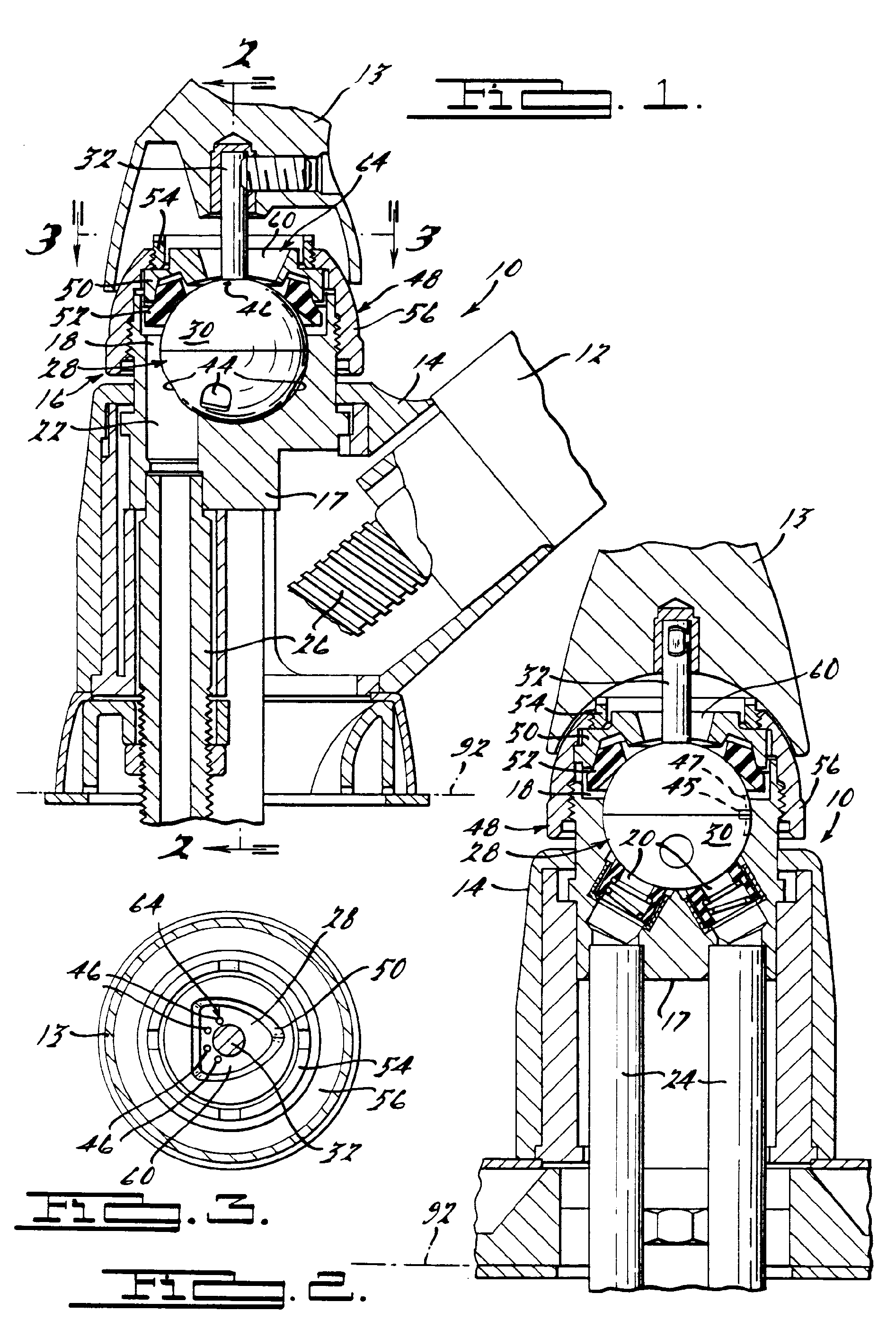
Figure 1 is a segmented side elevational view of a faucet with a faucet valve according
to the invention;
Figure 2 is a segmented view of the faucet valve taken at right angles from the view
shown in Figure 1;
Figure 3 is a cross-sectional view taken along the lines 3-3 in Figure 1.
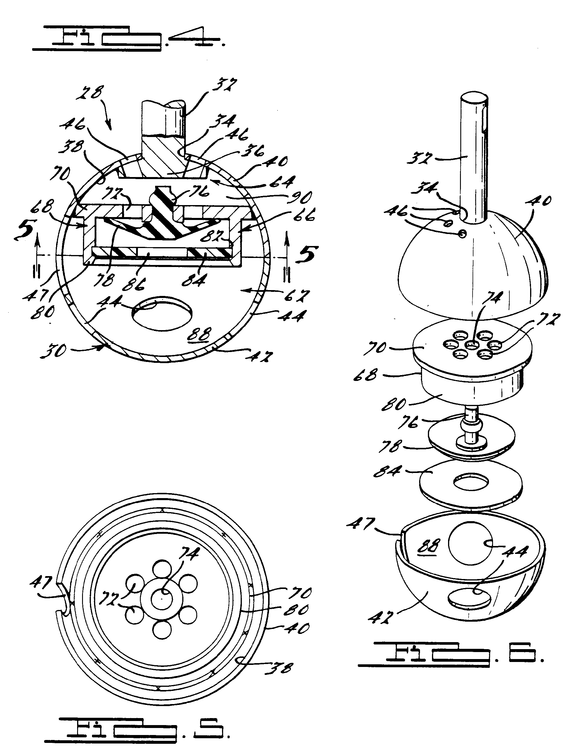
Figure 4 is an elevational cross-sectional view of the ball valve shown in Figure
1;
Figure 5 is a bottom partially assembled view of the ball valve, and
Figure 6 is an exploded perspective view of the ball valve.
DETAILED DESCRIPTION OF THE PREFERRED EMBODIMENT
[0012] Referring to Figures 1 and 2, a faucet or faucet valve 10 includes a faucet spout
12 and operable handle 13. The spout 12 is removably mounted to an escutcheon 14 which
is mounted about a lower housing section 17 of housing 16. The faucet valve housing
16 has a valve chamber 18 with two supply inlets 20 and a supply outlet 22. The supply
inlets are connected to supply pipes 24. The supply outlet 22 is connected to the
spout 12 through a flexible tube 26. Within the valve chamber 18 is mounted a ball
valve (ball valve element) 28.
[0013] As shown in more detail in Figures 4 and 6, the ball valve has a ball section 30
and a control stem 32. The ball section 30 comprises two halves 40 and 42 made from
stainless steel. Ball half 42 has a plurality of valve ports 44 therethrough. The
valve ports can be selectively aligned or misaligned with both supply inlets 20 and
in communication with supply outlet 22 to selectively close or open the supply inlets
to the supply outlet. When closed, the ball half 42 has its surface sealingly covering
supply inlets. Ball half 40 has the control stem 32 rigidly secured thereto. The control
stem 32 passes through an aperture 34 and has a larger base section 36 welded to the
interior wall 38 of the ball section 30. A plurality of vent apertures 46 pass through
ball half 40 and base 36 of stem 32.
[0014] As shown in Figures 1 and 2, the ball valve is fitted in chamber 18 of the housing
16. The ball valve is positioned correctly by a positioning post 45 extending from
section 17 and fitting in slot 47 in ball 30. A cap assembly 48 of the housing 16
includes an upper valve seat 50, a sealing ring 52, adjusting ring 54, and a screw
cover 56 which screws on the external portion of the lower section 17. The valve housing
16 is conventional in structure and is presently in production and found in the Delta
single handle kitchen faucet.
[0015] The cap assembly 48 forms an auxiliary opening 60 which receives control stem 32.
The vent apertures 46 as shown in Figure 3 are circumferentially spaced about the
control stem and are in communication with the auxiliary opening 60 and with the hollow
interior 62 of the ball section 30 to form an anti-siphon air passageway 64.
[0016] The vent apertures 46 are adjacent the control stem 32 such that the vent apertures
46 are always in communication with the auxiliary opening 60 independent of the operable
position of the control stem and to assure that the vent apertures 46 are in communication
with the auxiliary opening 60 particularly when the control valve is in the open position.
[0017] Referring to Figures 4, 5 and 6, a check valve 66 is mounted within the hollow interior
62 to allow air to pass from the auxiliary opening 60 through the passageway 64 into
the supply inlets 20 while preventing fluid from the supply inlets passing through
to the auxiliary opening 60. The check valve includes a cup-shaped member 68 that
has a disc section 70 sealingly welded at its periphery to the top half 40 of the
ball valve 28. The disc section has a plurality of apertures 72 and a central mounting
aperture 74. A central mounting aperture receives a stem 76 of flap valve 78. The
flap valve 78 covers the aperture 72 to allow the flow as above described. The cup-shaped
member 68 also has a cylindrical wall 80 surrounding the flap valve. The cylindrical
wall has an annular groove 82 which can receive the annular plastic snap ring 84.
The plastic snap ring has a central aperture 86. The snap ring 84 and cylindrical
wall 80 form a shield for the flap valve to reduce turbulence from disturbing the
flap valve 78 as fluid flows from the supply inlets 20 through the valve ports 44
and out through the supply outlet 22.
[0018] The ball valve 28 is assembled by having two halves 40 and 42 stamped. The control
stem 32 is then passed through aperture 30 for the top half and welded and has its
base section 36 welded in place. The vent apertures 46 are then drilled about the
control stem 32. Cup-shaped member 68 is then welded in place in the top half 40 as
shown in Figure 5. Flap valve 78 has a stem snap-fitted into the central mounting
aperture 74. The snap ring 84 is then snapped in place and the lower half 42 is then
welded to the top half in the appropriate position to form the complete ball valve
28. The ball valve is then mounted in the ball valve chamber in conventional fashion
with the cap assembly 48 screwed onto the lower housing section 58. Conventional one
way check valves, such as duck bill flap valves, are optionally placed in each supply
pipe 24 to reduce vacuum pull through the ball valve 28.
[0019] In operation, the ball valve 28 operates as a conventional ball valve by selectively
being operable via the valve handle 13. The valve ports 44 can be selectively positioned
to either cover or uncover both supply inlets to control volume and the mix from both
inlets passing through the lower half 88 of the hollow interior 62 and then out through
an additional valve port 44 and through the supply outlet 22.
[0020] If per chance there is a negative pressure in the supply inlets and the valve is
turned on, the negative pressure will open the flap valve 78 such that air can pass
through the passageway 64 formed by the auxiliary opening 60, the top half 90 of the
hollow interior 62 to the lower half 88 of the hollow interior 62, and through the
valve ports 44 to the supply inlets 20. Furthermore, if there is a slight vacuum pressure
still exerted on supply outlet 22, the height of the supply outlet 22 is significantly
higher than the flood plane indicated at 92 so that the risk of having any water being
siphoned back through the supply outlet is reduced significantly.
[0021] If the ball valve 28 needs replacing, it can be replaced in the conventional fashion
by merely removing handle 13 from the control stem 32 and unscrewing the cap assembly
48 after the water supply has been shut off. The ball valve 28 can then be removed
and replaced by a new ball valve 28 with the cap assembly 48 secured back onto the
lower housing section 58 and the handle 13 secured to the control stem 32.
[0022] In this fashion, a faucet spout that requires a vacuum breaker can incorporate the
vacuum breaker in the conventional housing with no changes in the escutcheon or increased
size of the valve housing 16. Furthermore, the position of the vacuum breaker is sufficiently
high to reduce the risk of back siphoning and is easily replaceable by merely replacing
the ball valve element 28. Furthermore, the vacuum breaker is sealed against leakage.
Furthermore, the vacuum breaker passageway is formed with no additional openings into
the valve housing because the opening that receives the control stem functions additionally
as part of the air passageway into the valve housing chamber.
1. Faucet valve (10) comprising a housing (16) having a valve chamber (18) and at
least one supply inlet (20) and a supply outlet (22), a rigid movable ball valve element
(28) within said valve chamber (18) operably movable to selectively cover and uncover
said at least one supply inlet (20) and closing and opening communication to said
supply outlet (22), characterized in that said housing (16) includes an auxiliary
opening (60) to said valve chamber (18) in communication with a passage (62) through
said ball valve element (28) forming an anti-siphon air passageway (64), said auxiliary
opening (60) being independent of said supply outlet (22), and in that it comprises
a one way check valve (66) mounted within said air passageway (64) to prevent fluid
from said at least one supply inlet (20) from exiting said auxiliary opening (60)
but allowing air to enter said air passageway (64) and bypassing said supply outlet
(22), said ball valve element (28) having valve port means (44) and at least one aperture
(46) forming said passage (62) and communicating with said opening (60), said disc
section (70) being attached to an interior wall of said ball valve element (28) with
said aperture (46) on one side and said valve port means (44) on another side of said
ball valve element (28) with respect to said disc section (70).
2. Faucet valve according to claim 1, characterized in that it comprises a seal (52)
operably mounted between said ball valve element (28) and said housing (16) to prevent
fluid from said valve chamber (18) from flowing between said ball valve element (28)
and housing (16) to said opening (60).
3. Faucet valve according to claim 1, characterized in that said check valve (66)
includes a disc section (70) having an outer periphery sealingly and rigidly attached
to an interior wall of said valve element (28).
4. Faucet valve according to claim 3, characterized in that said disc section (70)
has aperture means (72) formed therein, and in that it further comprises at least
one flap valve (78) mounted to normally cover said aperture means (72) and to prevent
hydraulic fluid from said inlet (20) from leaking therethrough and to said aperture
(46) in said ball valve element (28) and said opening (60) in said housing (16).
5. Faucet valve according to claim 4, characterized in that it further comprises at
least one shield defined by a cylindrical wall (80) extending downwardly from said
disc section (70), whereby to reduce exposure of said flap valve (78) from turbulence
of said fluid from said at least one supply inlet (20) flowing through said valve
port means (44) and to said supply outlet (22).
6. Faucet valve according to claim 5, characterized in that said shield further comprises
an annular disc (84) having at least one central aperture (86) formed therein and
being attached to the lower end of said cylindrical wall (80) below said flap valve
(78).
7. Faucet valve according to claim 1, 2, 3, 4 or 5, characterized in that said ball
valve element (28) comprises at least one control stem (32) having a base portion
(36) affixed to an interior wall (38) of the ball section (30) defined by the ball
valve element (28).
8. Faucet valve according to claims 1 or 4 and 7, characterized in that said at least
one aperture comprises a plurality of apertures (46) spaced circumferentially about
said control stem (32) and adjacent thereto, said apertures (46) extending through
said base portion (36) of said control stem (32) and through said ball section (30)
of said ball valve element (28).
9. Faucet valve according to one or more of the preceding claims wherein said at least
one supply inlet (20) comprises two supply inlets for hot and cold water respectively,
and preferably wherein said flap valve (78) is made of resilient elastomeric material.
10. A ball valve element (28) being used in a faucet valve (10) as defined in any
of the preceding claims, said ball valve element (28) comprising a ball section (30)
having valve ports (44) therethrough, and a control stem (32) extending from said
ball section (30), characterized in that said ball section (30) is hollow and has
at least one vent aperture (46) extending therethrough, a check valve (66) being mounted
within said ball section (30) and dividing the interior (62) into a first and second
portion (88, 90) with said valve ports (44) at said first portion (88) and said at
least one vent aperture (46) at said second portion (90), said check valve (66) being
operably constructed to allow flow only from said second (90) to said first (88) portion.
11. A ball valve according to claim 10, characterized in that it comprises a plurality
of vent apertures (46) circumferentially spaced about said control stem (32).
12. A ball valve according to claim 10 characterized in that said control stem (32)
has a base portion (36) affixed to the interior wall (38) of said ball section (30),
and in that said vent apertures (46) are circumferentially spaced about said stem
(32) adjacent to said base portion (36), said apertures (46) extending through said
base portion (36) and said ball section (30).
13. A ball valve according to claim 10, characterized in that said check valve (66)
includes a disc section (70) having an outer periphery sealingly and rigidly attached
to an interior wall (38) of said ball valve element with said apertures (46) on one
side and said valve ports (44) on another side of said ball valve element (28) with
respect to said disc section (70), said disc section (70) having an aperture means
(72) formed therethrough, said ball valve element (28) further comprising an elastomeric
resilient flap valve (78) mounted to normally cover said aperture means (72) through
said disc section (70), and a shield (68) mounted about said flap valve (78) to reduce
exposure of said flap valve (78) from any turbulence of said fluid flowing through
said first portion (88) of said ball interior.
14. A ball valve according to claim 13, characterized in that said shield (68) includes
a cylindrical wall (80) downwardly extending from said disc section (70) and surrounding
said flap valve (78), and a plastic ring (84) having a central aperture (86) fitted
at the lower end of said cylindrical wall (80) below said flap valve (78).
15. A ball valve according to claim 13, characterized in that said ball section (30)
includes a first stamped half (40) including said at least one vent aperture (46)
and said stem (32) secured thereto, said disc section (70) being welded to said first
half (40), a second stamped half (42) having said valve ports (44) and being welded
to said first half (40).
16. A ball valve according to claim 15, wherein said first and second halves (40,
42) are made from stainless steel.
1. Absperrventil (10) mit einem Gehäuse (16), das eine Ventilkammer (18) und wenigstens
eine Einlaßöffnung (20) und eine Auslaßöffnung (22) aufweist, mit einem starren, beweglichen
Ballventilelement (28) innerhalb der Ventilkammer (18), welche bedienbar beweglich
zum selektiven Bedecken und Nichtbedecken der wenigstens einen Einlaßöffnung (20)
und zum Schließen und Öffnen der Verbindung zu der Auslaßöffnung (22) ist, dadurch
gekennzeichnet, daß das Gehäuse (16) eine Zusatzöffnung (60) zu der Ventilkammer (18)
in Verbindung mit einem Durchlaß (62) durch das Ballventil (28) aufweist, die einen
Anti-Syphon-Luftdurchtrittsweg (64) bildet, wobei die Zusatzöffnung (60) unabhängig
von der Auslaßöffnung (22) ist, und daß es ein Einwegkontrollventil (66) aufweist,
das innerhalb des Luftdurchtrittsweges (64) angeordnet ist, um zu verhindern, daß
ein Fluid aus der wenigstens einen Einlaßöffnung (20) aus der Zusatzöffnung (60) austritt,
welches aber einen Lufteintritt durch den Luftdurchtrittsweg (64) und einen Bypass
der Auslaßöffnung (22) erlaubt, wobei das Ballventilelement (28) Durchgangsmittel
(44) und wenigstens eine Öffnung (46) aufweist, die den Durchlaß (62) bilden und mit
der Öffnung (60) in Verbindung stehen, wobei ein Scheibenbereich (70) an einer inneren
Wand des Ballventilelementes (28) mit der Öffnung (46) auf einer Seite und den Durchgangsmitteln
(44) auf einer anderen Seite des Ballventilelementes (28) in bezug auf den Scheibenbereich
(70) angebracht ist.
2. Absperrventil nach Anspruch 1, dadurch gekennzeichnet, daß es eine Dichtung (52)
aufweist, die bedienbar zwischen dem Ballventilelement (28) und dem Gehäuse (16) angeordnet
ist, um zu verhindern, daß ein Fluid aus der Ventilkammer (18) zwischen das Ballventil
(28) und das Gehäuse (16) zu der Öffnung (60) fließt.
3. Absperrventil. nach Anspruch 1, dadurch gekennzeichnet, daß das Kontrollventil
(66) einen Scheibenbereich (70) aufweist, welcher einen äußeren Umfang hat, der dicht
und fest an der inneren Wand des Ventilelementes (28) angebracht ist.
4. Absperrventil nach Anspruch 3, dadurch gekennzeichnet, daß der Scheibenbereich
(70) in diesem ausgebildete Öffnungsmittel (72) aufweist, und daß es außerdem wenigstens
ein Flügelventil (78) aufweist, das angeordnet ist, um normalerweise die Öffnungsmittel
(72) abzudecken und um zu verhindern, daß ein hydraulisches Fluid aus der Einlaßöffnung
(20) durch diese und die Öffnung (46) in dem Ballventilelement (28) und die Öffnung
(60) in dem Gehäuse (19) austritt.
5. Absperrventil nach Anspruch 4, dadurch gekennzeichnet, daß es außerdem wenigstens
einen durch eine zylindrische Wand (80) begrenzten Schild aufweist, der sich abwärts
von dem Scheibenbereich (70) erstreckt, um eine Beaufschlagung des Flügelventils (78)
mit der Turbulenz des Fluids aus der wenigstens einen Einlaßöffnung (20), das durch
die Ventilöffnungsmittel (44) und zu der Auslaßöffnung (22) fließt, zu verringern.
6. Absperrventil nach Anspruch 5, dadurch gekennzeichnet, daß der Schirm außerdem
eine ringförmige Scheibe (84) aufweist, die wenigstens eine darin ausgebildete zentrale
Öffnung (86) aufweist und am unteren Ende der zylindrischen Wand (80) unterhalb des
Flügelventils (78) angebracht ist.
7. Absperrventil nach Anspruch 1, 2, 3, 4 oder 5, dadurch gekennzeichnet, daß das
Ballventilelement (28) wenigstens einen Steuerkolben (32) mit einem Basisbereich (36)
aufweist, der an der durch das Ballventilelement (28) begrenzten inneren Wand (38)
des Ballbereiches (30) befestigt ist.
8. Absperrventil nach Anspruch 1 oder 4 und 7, dadurch gekennzeichnet, daß die wenigstens
eine Öffnung eine Mehrzahl von Öffnungen (46) aufweist, die umfänglich um den Steuerkolben
(32) und benachbart dazu angeordnet sind, wobei die Öffnungen (46) sich durch den
Basisbereich (36) des Steuerkolbens (32) und den Ballbereich (30) des Ballventilelementes
(28) erstrecken.
9. Absperrventil nach einem oder mehreren der vorangegangenen Ansprüche, dadurch gekennzeichnet,
daß die wenigstens eine Einlaßöffnung (20) zwei Einlässe für heißes bzw. kaltes Wasser
aufweist und daß vorzugsweise das Flügelventil (78) aus federndem elastomeren Material
besteht.
10. Ballventilelement (28) zur Verwendung in einem Absperrventil (10) nach einem der
vorangehenden Ansprüche, wobei das Ballventilelement (28) einen Ballbereich (30) mit
Ventilöffnungen (44) dadurch und einen sich von dem Ballbereich (30) erstreckenden
Steuerkolben (32) aufweist, dadurch gekennzeichnet, daß der Ballbereich (30) hohl
ist und wenigstens eine sich dadurch erstreckende Lüftungsöffnung (46) aufweist, wobei
ein Kontrollventil (66) innerhalb des Ballbereiches (30) angeordnet ist und das Innere
(62) in einen ersten und zweiten Bereich (88,90) mit den Ventilöffnungen (44) im ersten
Bereich (88) und der wenigstens einen Lüftungsöffnung (46) im zweiten Bereich (90)
teilt, wobei das Kontrollventil (66) bedienbar so ausgebildet ist, daß es einen Fluß
nur vom zweiten (90) zum ersten (88) Bereich erlaubt.
11. Ballventil nach Anspruch 10, dadurch gekennzeichnet, daß es eine Mehrzahl von
Lüftungsöffnungen (46) aufweist, die umfänglich um den Steuerkolben (32) angeordnet
sind.
12. Ballventil nach Anspruch 10, dadurch gekennzeichnet, daß der Steuerkolben (32)
einen Basisbereich (36) aufweist, der an der inneren Wand (38) des Ballbereiches (30)
befestigt ist, und daß die Lüftungsöffnungen (46) umfänglich um den Kolben (32) benachbart
zum Basisbereich (36) angeordnet sind, wobei die Öffnungen (46) sich durch den Basisbereich
(36) und den Ballbereich (30) erstrecken.
13. Ballventil nach Anspruch 10, dadurch gekennzeichnet, daß das Kontrollventil (66)
einen Scheibenbereich (70) aufweist, der einen dicht und fest an der inneren Wand
(38) des Ballventilelementes angebrachten Umfang mit den Öffnungen (46) auf einer
Seite und den Ventilöffnungen (44) auf der anderen Seite des Ballventilelementes (28)
in bezug auf den Scheibenbereich (70) aufweist, wobei der Scheibenbereich (70) durch
diesen hindurch ausgebildete Öffnungsmittel (72) aufweist, wobei das Ballventilelement
(28) außerdem ein elastomeres federndes Flügelventil (78), das zum normalerweisen
Abdecken der Öffnungsmittel (72) durch den Scheibenbereich (70) angeordnet ist, und
einen Schirm (68) aufweist, der um das Flügelventil (78) herum angeordnet ist, um
eine Beaufschlagung des Flügelventils (78) mit irgendeiner Turbulenz des durch den
ersten Bereich (88) des Ballinnenraums hindurchtretenden Fluids zu verringern.
14. Ballventil nach Anspruch 13, dadurch gekennzeichnet, daß der Schirm (68) eine
zylindrische Wand (80), die sich abwärts von dem Scheibenbereich (70) erstreckt und
das Flügelventil (78) umgibt, und einen Plastikring (84) mit einer zentralen Öffnung
(86) aufweist, der am unteren Ende der zylindrischen Wand (80) unterhalb des Flügelventils
(78) eingepaßt ist.
15. Ballventil nach Anspruch 13, dadurch gekennzeichnet, daß der Ballbereich (30)
eine erste gepreßte Hälfte (40), die die wenigstens eine Lüftungsöffnung (46) aufweist
und an der der kolben (32) gesichert ist, wobei der Scheibenbereich (70) an der ersten
Hälfte (40) angeschweißt ist, und eine zweite gepreßte Hälfte (42) aufweist, die die
Ventilöffnungen (44) aufweist und an der ersten Hälfte (40) angeschweißt ist.
16. Ballventil nach Anspruch 15, dadurch gekennzeichnet, daß die erste und zweite
Hälfte (40,42) aus nichtrostendem Stahl bestehen.
1. Robinet (10) comprenant un boîtier (16) ayant une chambre de vanne (18) et au moins
une entrée d'alimentation (20) et une sortie d'alimentation (22), un élément de vanne
à sphère rigide mobile (28) disposé dans ladite chambre de vanne (18) pouvant être
déplacé sélectivement pour couvrir et découvrir ladite au moins une entrée d'alimentation
(20) et couper et rétablir la communication vers ladite sortie d'alimentation (22),
caractérisé en ce que ledit boîtier (16) comprend un orifice auxiliaire (60) s'ouvrant
vers ladite chambre de vanne (18) et communiquant avec un passage (62) à travers ledit
élément de vanne à sphère (28) pour former un chemin d'air anti-siphon (64), ledit
orifice auxiliaire (60) étant indépendant de ladite sortie d'alimentation (22), et
en ce qu'il comprend une soupape d'arrêt unidirectionnelle (66) montée dans ledit
chemin d'air (64) pour empêcher du fluide provenant de ladite au moins une entrée
d'alimentation (20) de sortir dudit orifice auxiliaire (60) mais permettant à de l'air
d'entrer dans ledit chemin d'air (64) en court-circuitant ladite sortie d'alimentation
(22), ledit élément de vanne à sphère (28) comprenant des moyens d'accès de vanne
(44) et au moins une ouverture (46) formant ledit passage (62) et communiquant avec
ledit orifice (60), un disque (70) étant fixé à une paroi interne dudit élément de
vanne à sphère (28), ladite ouverture (46) étant d'un côté et lesdits moyens d'accès
de vanne (44) de l'autre côté dudit élément de vanne à sphère (28) par rapport au
disque (70).
2. Robinet selon la revendication 1, caractérisé en ce qu'il comprend un joint (52)
monté entre ledit élément de vanne à sphère (28) et ledit boîtier (16) pour empêcher
du fluide provenant de ladite chambre de vanne (18) de s'écouler entre ledit élément
de vanne à sphère (28) et le boîtier (16) vers ledit orifice (60).
3. Robinet selon la revendication 1, caractérisé en ce que ladite soupape d'arrêt
(66) comprend un disque (70) dont la périphérie est fixée de façon étanche et rigide
à une paroi interne dudit élément de vanne à sphère (28).
4. Robinet selon la revendication 3, caractérisé en ce que le disque (70) comprend
des moyens d'ouverture (72), et en ce que il comprend en outre une soupape à membrane
(78) montée pour normalement couvrir lesdits moyens d'ouverture (72) et pour empêcher
du fluide hydraulique de fuir à travers les moyens d'ouverture et vers ladite ouverture
(46) dans ledit élément de vanne à sphère (28) et vers ledit orifice (60) dans ledit
boîtier (16).
5. Robinet selon la revendication 4, caractérisé en ce qu'il comprend en outre au
moins un écran défini par une paroi cylindrique (80) s'étendant vers le bas dudit
disque (70), afin de réduire l'exposition de ladite soupape à membrane (78) à la turbulence
dudit fluide provenant de ladite au moins une entrée d'alimentation (20) s'écoulant
à travers lesdits moyens d'accès de vanne (44) et vers ladite sortie d'alimentation
(22).
6. Robinet selon la revendication 5, caractérisé en ce que ledit écran comprend en
outre un disque annulaire (84) ayant au moins une ouverture centrale (86) et étant
fixé à l'extrémité inférieure de ladite paroi cylindrique (80) sous ladite soupape
à membrane (78).
7. Robinet selon la revendication 1, 2, 3, 4 ou 5, caractérisé en ce que ledit élément
de vanne à sphère (28) comprend au moins une tige de commande (32) ayant une base
(36) solidaire d'une paroi intérieure (38) de la section de sphère (30) définie par
ledit élément de vanne à sphère (28).
8. Robinet selon les revendications 1 ou 4 et 7, caractérisé en ce que ladite au moins
une ouverture comprend une pluralité d'ouvertures (46) espacées circonférentiellement
autour de ladite tige de commande (32) et adjacentes à cette tige, lesdites ouvertures
(46) s'étendant à travers ladite base (36) de ladite tige de commande (32) et à travers
ladite section de sphère (30) dudit élément de vanne à sphère (28).
9. Robinet selon l'une ou plusieurs des revendications précédentes, dans lequel ladite
au moins une entrée d'alimentation (20) comprend deux entrées d'alimentation pour
de l'eau froide et chaude respectivement, et dans lequel, de préférence, ladite soupape
à membrane (78) est faite en matériau élastomère élastique.
10. Elément de vanne à sphère (28) utilisé dans un robinet (10) tel que défini dans
l'une quelconque des revendications précédentes, ledit élément de vanne à sphère (28)
comprenant une section de sphère (30) ayant des accès de vanne (44) la traversant,
et une tige de commande (32) s'étendant à partir de ladite section de sphère (30),
caractérisé en ce que la section de sphère (30) est creuse et comprend au moins une
ouverture de soupape (46), une soupape d'arrêt (66) étant montée à l'intérieur de
ladite section de sphère (30) et divisant l'intérieur (62) en une première et une
deuxième partie (88, 90), lesdits accès de vanne (44) étant dans la première partie
(88) et ladite au moins une ouverture de soupape (46) étant dans la deuxième partie
(90), ladite soupape d'arrêt (66) étant construite pour permettre seulement un écoulement
de ladite deuxième partie (90) vers ladite première partie (88).
11. Vanne à sphère selon la revendication 10, caractérisée en ce qu'elle comprend
une pluralité d'ouvertures de soupape (46) circonférentiellement espacées autour de
ladite tige de commande (32).
12. Vanne à sphère selon la revendication 10, caractérisée en ce que ladite tige de
commande (32) comprend une base (36) solidaire de la paroi intérieure (38) de ladite
section de sphère (30), et en ce que lesdites ouvertures de soupape (46) sont circonférentiellement
espacées autour de ladite tige (32) et adjacentes à ladite base (36), lesdites ouvertures
(46) s'étendant à travers ladite base (36) et ladite section de sphère (30).
13. Vanne à sphère selon la revendication 10, caractérisée en ce que ladite soupape
d'arrêt (66) comprend un disque (70) dont la périphérie est fixée de manière étanche
et rigide à une paroi intérieure (38) dudit élément de vanne à sphère, lesdites ouvertures
(46) étant d'un côté et lesdits accès de vanne (44) de l'autre côté dudit élément
de vanne à sphère (28) par rapport audit disque (70), ledit disque (70) comprenant
des moyens d'ouverture (72), ledit élément de vanne à sphère (28) comprenant en outre
une soupape à membrane élastomère élastique montée pour normalement couvrir lesdits
moyens d'ouverture (72) à travers ledit disque (70), et un écran (68) monté autour
de la soupape à membrane (78) pour réduire l'exposition de ladite soupape à membrane
(78) à toute turbulence dudit fluide s'écoulant à travers ladite première partie (88)
dudit intérieur de sphère.
14. Vanne à sphère selon la revendication 13, caractérisée en ce que ledit écran (68)
comprend une paroi cylindrique (80) s'étendant vers le bas à partir dudit disque (70)
et entourant ladite soupape à membrane (78), et un anneau plastique (84) ayant une
ouverture centrale (86) et ajusté à l'extrémité inférieure de ladite paroi cylindrique
(80) sous ladite soupape à membrane (78).
15. Vanne à sphère selon la revendication (13), caractérisée en ce que ladite section
de sphère (30) comprend une première moitié matricée (40) comprenant ladite au moins
une ouverture de soupape (46) et ladite tige (32) qui y est fixée, ledit disque (70)
étant soudé à ladite première moitié (40), une deuxième moitié matricée (42) comprenant
lesdits accès (44) et étant soudé à la première moitié (40).
16. Vanne à sphère selon la revendication (15), dans laquelle lesdites première et
deuxième moitiés (40, 42) sont en acier inoxydable.