| (19) |
 |
|
(11) |
EP 0 302 674 B1 |
| (12) |
EUROPEAN PATENT SPECIFICATION |
| (45) |
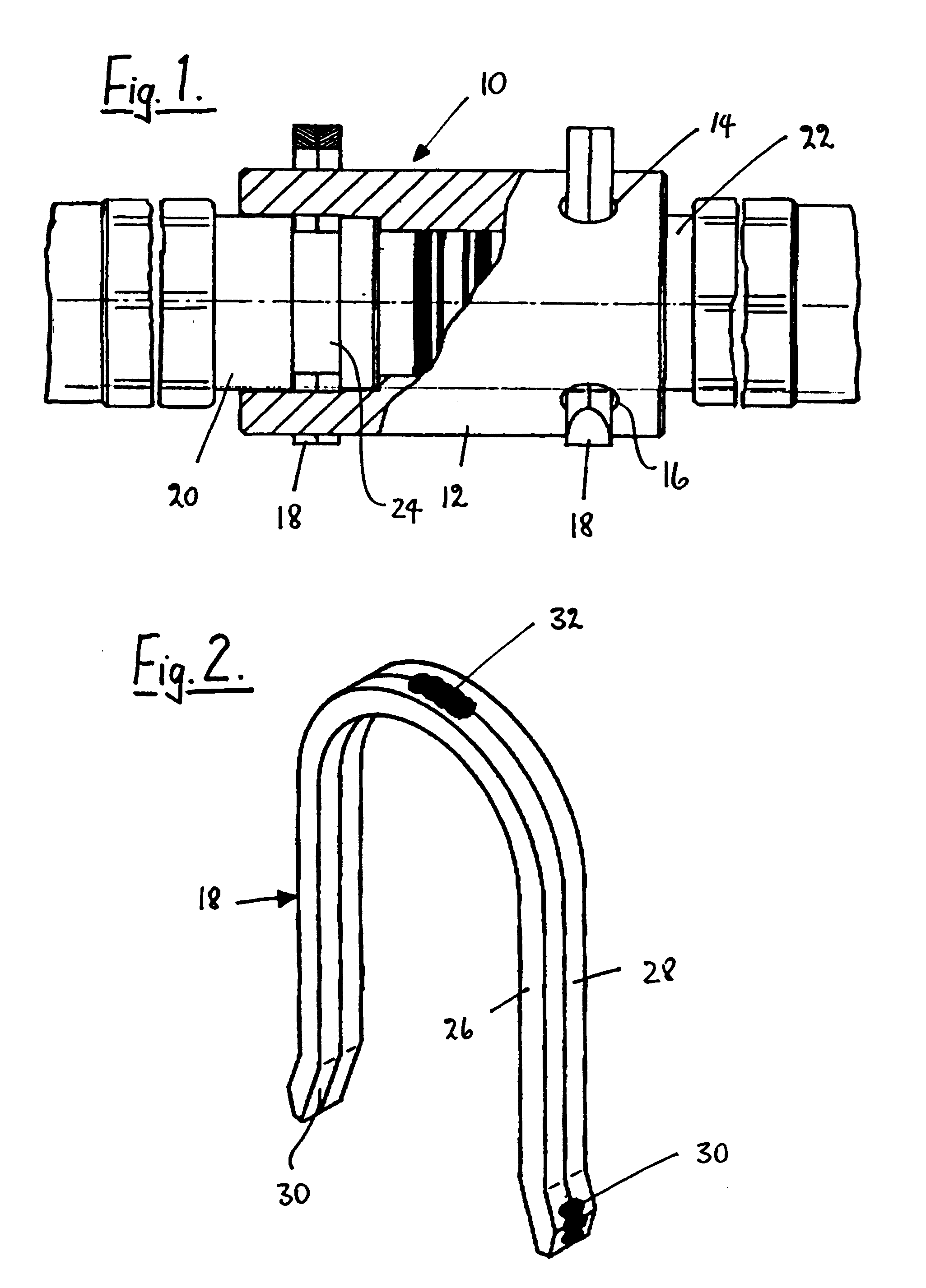
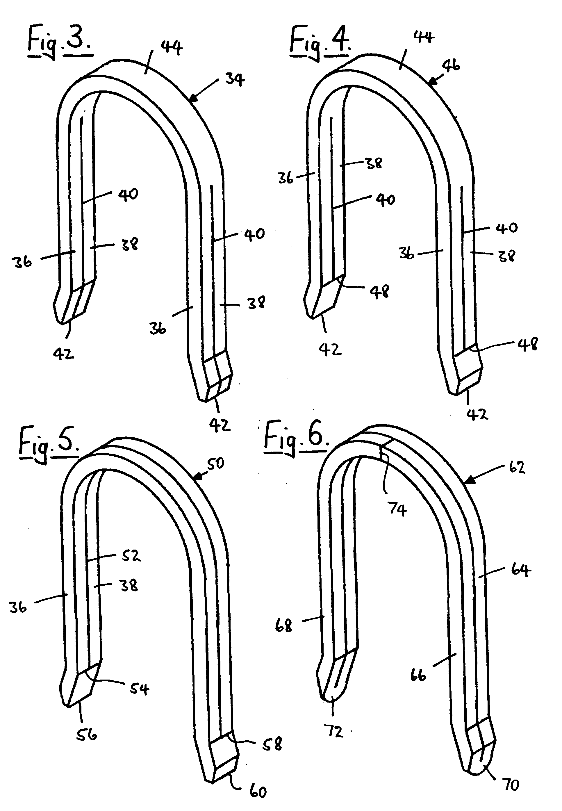
Mention of the grant of the patent: |
|
22.07.1992 Bulletin 1992/30 |
| (22) |
Date of filing: 29.07.1988 |
|
| (51) |
International Patent Classification (IPC)5: F16L 37/14 |
|
| (54) |
A laminated cotter pin or locking staple and couplings and connections incorporating
it
Geschichteter Splint oder Verriegelungsklammer und Kupplungen und Verbindungen damit
Goupille laminé ou agrafe de verrouillage laminé et raccords et connections avec celui-ci
|
| (84) |
Designated Contracting States: |
|
AT BE DE ES FR GB IT NL SE |
| (30) |
Priority: |
04.08.1987 GB 8718392
|
| (43) |
Date of publication of application: |
|
08.02.1989 Bulletin 1989/06 |
| (73) |
Proprietor: DAYCO EUROPE LIMITED |
|
Halesowen
West Midlands B62 8DR (GB) |
|
| (72) |
Inventors: |
|
- Hinksman, Patrick Bryan
Kinver
Near Stourbridge
West Midlands (GB)
- Long, Gary
Stourport-on-Severn
West Midlands (GB)
|
| (74) |
Representative: Heath, Derek James et al |
|
BROMHEAD & CO.
19 Buckingham Street
London WC2N 6EF
London WC2N 6EF (GB) |
| (56) |
References cited: :
DE-U- 7 241 954
GB-A- 941 545
|
FR-A- 1 398 823
US-A- 3 929 357
|
|
| |
|
|
|
|
| |
|
| Note: Within nine months from the publication of the mention of the grant of the European
patent, any person may give notice to the European Patent Office of opposition to
the European patent
granted. Notice of opposition shall be filed in a written reasoned statement. It shall
not be deemed to
have been filed until the opposition fee has been paid. (Art. 99(1) European Patent
Convention).
|
[0001] This invention relates to a generally U-shaped laminated cotter pin or locking staple,
especially for use in detachable hose couplings or pipe or tube connections.
[0002] British Patent No. 941,545 describes hose or pipe connections and couplings wherein
a U-shaped cotter pin is used to hold two parts of the connection or coupling together
in a detachable manner. Such an arrangement has the advantage that unsatisfactory
connecting means such as screw joints or bayonet joints wherein a turning or twisting
motion is required are completely avoided. This is of particular advantage in mines
and other underground workings where hose or pipe connections or couplings are frequently
located in inaccessible and inconvenient places.
[0003] The present invention is concerned with an improvement in the U-shaped cotter pin
described in that prior Patent, and arises out of an emerging market demand for cotter
pins or locking staples which can accept the high levels of dynamic loading which
are experienced in modern hydraulic installations such as those used in mines.
[0004] With this consideration in mind, the present invention is directed to a generally
U-shaped laminated cotter pin or locking staple as set forth in claim 1. The invention
also extends to couplings and connections incorporating such a staple.
[0005] It is surprising from an engineering point of view that a laminated cotter pin or
locking staple of this construction can accept higher levels of dynamic loading than
a solid cotter pin or staple of the construction shown in GB-A-941,545 even if the
width of the prior staple is increased so as to be, say, twice that of the cotter
pin illustrated in that Patent. It is however a fact that the laminated cotter pin
or locking staple with which the present invention is concerned gives substantially
better results than a solid cotter pin or locking staple of increased width.
[0006] Admittedly, FR-A-1 398 823 describes a generally U-shaped locking staple comprising
joined-together plies. Here, however, the opposing surfaces of the plies lie at right-angles
to the outer side surfaces of the locking staple, and its cross-section is non-uniform.
[0007] The leaves or plies of the cotter pin or staple can be joined together - for example
by welding - at or near their free ends and/or at the curved intermediate portion
of the cotter pin or staple. However, as will be explained below, other ways of joining
the leaves or plies together are possible. The benefit of joining the leaves or plies
together is that the cotter pin or staple will then be inserted into a hose or pipe
connection or coupling as a unit. Thus, if the leaves or plies were not to be joined
in this way, it would then make it possible for a mining technician to insert only
one ply or leaf into a connection or coupling which could be hazardous under normal
operating conditions. Alternatively, he might insert a nail or other unsatisfactory
packing element to take the place of a second leaf or ply.
[0008] Some examples of laminated cotter pins or locking staples in accordance with the
invention are illustrated in the accompanying drawings, in which -
Figure 1 is a part-sectional side view through a hose or pipe connection or coupling
having detachable parts which are locked together by two U-shaped laminated cotter
pins or locking staples in accordance with the invention:
Figure 2 is an enlarged perspective view of either one of the two cotter pins or locking
staples shown in Figure 1: and
Figures 3 - 6 are perspective views similar to Figure 2 of four further forms of cotter
pin or locking staple in accordance with the invention.
[0009] Figure 1 shows a hose or pipe connection or coupling 10 for use, for example, in
mining installations to convey hydraulic fluid under pressure to and from mining equipment.
It includes a sleeve 12 having two pairs of circular openings 14 and 16 on either
side of a vertical plane passing through the longitudinal axis of the sleeve which
receive respective U-shaped cotter pins or locking staples 18 which lock the sleeve
on to respective coupling members 20 and 22. For this purpose, the two coupling members
20 and 22 are each provided with an annular groove 24 which tangentially receives
portions of the legs of the respective staples 18. Locking of the two coupling members
20 and 22 on to the sleeve 18 is therefore effected by inserting the staples into
the respective holes 14 and 16 and by withdrawing the staples from those holes when
it is desired to detach the parts of the coupling from each other.
[0010] Because of the high levels of dynamic loading which are experienced in modern hydraulic
installations, each staple 18 is of uniform cross-section substantially throughout
its length and is made of laminated form as shown in Figure 2 so as to comprise two
joined-together leaves or plies 26 and 28. These two plies are of exactly the same
shape as each other and they are welded together at their free ends 30 and at their
curved intermediae portions 32. This means that their opposing surfaces, whilst being
in close contact with each other, are joined at only three spaced-apart points, the
opposing surfaces being substantially parallel to the outer side surfaces of the staple
18. Surprising as it may seem, such a construction gives better results from the point
of view of resistance to dynamic loading than a single solid staple having the same
width as that shown in Figure 2.
[0011] Although Figures 2 to 6 each show a staple made from square-sectioned plies substantially
any cross-sectional shape for each ply is possible, for example round section or hexagonal
section. Furthermore, one of the plies of one staple may have a different cross section
from the other ply of that same staple.
[0012] Figures 3 to 6 show alternative forms of staple which achieve the same results as
that shown in Figure 2. Thus, Figure 3 shows a staple 34 having two plies 36 and 38
formed by cutting slits 40 in the two legs of the staple from their extreme ends 42.
In this case, therefore, the two plies 36 and 38 are joined together over the solid
curved central section 44 of the staple.
[0013] Figure 4 illustrates a similar form of staple 46 to that shown in Figure 3 except
that the slits 40 start from a point 48 displaced upwardly by a small distance from
the extreme ends 42 of the staple. In other words, the two plies 36 and 38 in this
construction are joined together both at the central portion 44 of the staple and
at their end portions.
[0014] The staple 50 shown in Figure 5 has the plies 36 and 38 separated by a single slit
52 which extends without interruption from a point 54 near the extreme end 56 of one
leg right round to a corresponding point 58 displaced from the extreme end 60 of the
other leg. This means that the staple 50 has its plies joined together at the end
portions only.
[0015] Figure 6 shows a staple 62 made of a single length of metal which is first bent into
a U-shape so as to form one ply 64, after which the portions 66 and 68 are bent round
at 70 and 72 respectively so as to form a second ply having a welded-together butt
joint 74 where the two bent-round portions 66 and 68 meet one another. The two plies
of the staple 62 are therefore joined together at the portions 70 and 72.
[0016] Although the various staples shown in the drawings are all provided with just two
plies, it is to be understood that staples in accordance with the invention can have
three or more plies where this is desired.
[0017] Staples in accordance with the invention will normally be made of high-quality steel
to enable them to withstand the dynamic loading to which they are subjected during
normal use of hose or pipe connections or couplings with which they are used. Where
it is desirable to prevent rusting or corrosion of the staples, they could of course
be made of a non-corroding metal or alloy such as stainless steel or bronze.
1. A generally U-shaped cotter pin or locking staple (18), especially for holding together,
in a detachable manner, two parts (12, 20; 12,22) of a hose coupling, pipe connection
or tube connection (10), wherein at least a portion of each leg of the cotter pin
or locking staple (18) comprises two or more joined-together leaves or plies (26,
28), characterised in that the pin or staple (18) is of uniform cross-section substantially throughout
its length and that the opposing surfaces of the plies (26, 28) lie substantially
parallel to the outer transverse surfaces of the pin or staple (18).
2. A cotter pin or locking staple according to claim 1, characterised in that the leaves or plies (26, 28) are joined together, for example by welding,
at or near their free ends (30) and/or at the curved intermediate portion (32) of
the cotter pin or staple (18).
3. A cotter pin or locking staple according to claim 1 or claim 2, characterised in that the leaves or plies (26, 28) are of exactly the same shape as each other.
4. A cotter pin or locking staple according to any one of claims 1-3, characterised in that the leaves or plies (26, 28) are of square-section, round section or hexagonal
section.
5. A cotter pin or locking staple according to any one of claims 1-3, characterised in that the leaves or plies (26, 28) are of different cross-section from each other.
6. A cotter pin or locking staple according to claim 1, characterised in that the leaves or plies (36, 38) are formed by slits (40) in the two legs of
the pin or staple (34), which slits stop short of the curved central section (44)
of the pin or staple.
7. A cotter pin or locking staple according to claim 1, characterised in that the leaves
or plies (36, 38) are formed by slits (40) which start from points (48) displaced
from the extreme ends (42) of the pin or staple (46) and which stop short of the central
portion (44) of the pin or staple.
8. A cotter pin or locking staple according to claim 1, characterised in that the leaves or plies (36, 38) are formed by a single slit (52) which extends
without interruption from a point (54) near the extreme end (56) of one leg right
round to a corresponding point (58) displaced from the extreme end (60) of the other
leg so that the pin or staple (50) has its leaves or plies joined together at the
end portions only.
9. A cotter pin or locking staple according to claim 1 characterised in that it is made from a single length of metal which has been first bent into a
U-shape so as to form one leaf or ply (64) and which has then had its end portions
(66, 68) bent round so as to form a second leaf or ply having a welded-together butt
joint (74) where the two bent-round portions (66, 68) meet one another.
10. A hose coupling, pipe connection or tube connection (10) comprising two tubular parts
(12, 20; 12, 22) which are detachably held together by a U-shaped cotter pin or locking
staple (18), wherein the U-shaped cotter pin or locking staple (18) is in accordance
with any one of claims 1-9 and one part (12) of the coupling has a pair of openings
(14; 16) serving to receive the respective legs of the cotter pin or locking staple
(18) while the other part (20; 22) of the coupling is provided with an annular groove
(24) which tangentially receives portions of the legs of the cotter pin or locking
staple (18), the size of the openings (14; 16) and the size of the groove (24) being
matched to the dimensions of the cotter pin or locking staple (18).
11. A hose coupling, pipe connection or tube connection according to claim 10, characterised by a sleeve (12) having two pairs of openings (14; 16) located on either side of
a vertical plane passing through the longitudinal axis of the sleeve, which openings
(14; 16) receive the legs of respective ones of the U-shaped cotter pins or locking
staples (18) which lock the sleeve on to respective coupling members (20, 22), and
that the two coupling members (20, 22) are each provided with an annular groove (24)
which tangentially receives portions of the legs of the respective staples (18).
1. Clavette ou agrafe de blocage en forme générale de U (18), spécialement destinée à
maintenir ensemble, de manière amovible, deux éléments (12, 20 ; 12, 22) d'un raccord
de flexibles, d'une connexion de tuyaux ou d'une connexion de tubes (10), dans laquelle
au moins une partie de chaque branche de la clavette ou de l'agrafe de blocage (18)
comprend deux ou plusieurs feuilles ou plis assemblés (26, 28), caractérisée en ce que la clavette ou l'agrafe (18) est de section transversale uniforme sensiblement
sur toute sa longueur, et en ce que les surfaces opposées des plis (26, 28) sont sensiblement
parallèles aux surfaces transversales extérieures de la clavette ou de l'agrafe (18).
2. Clavette ou agrafe de blocage conforme à la revendication 1, caractérisée en ce que les feuilles ou les plis (26, 28) sont assemblés, par exemple par soudage,
à ou près de leurs extrémités libres (30) et/ou au niveau de la partie intermédiaire
courbe (32) de la clavette ou de l'agrafe (18).
3. Clavette ou agrafe de blocage conforme à la revendication 1 ou à la revendication
2, caractérisée en ce que les feuilles ou les plis (26, 28) sont exactement de même forme.
4. Clavette ou agrafe de blocage conforme à l'une quelconque des revendications 1 à 3,
caractérisée en ce que les feuilles ou les plis (26, 28) sont de section carrée, de section ronde
ou de section hexagonale.
5. Clavette ou agrafe de blocage conforme à l'une quelconque des revendications 1 à 3,
caractérisée en ce que les feuilles ou les plis (26, 28) sont de section transversale différente
l'un de l'autre.
6. Clavette ou agrafe de blocage conforme à la revendication 1, caractérisée en ce que les feuilles ou les plis (36, 38) sont formées par des fentes (40) pratiquées
dans les deux branches de la clavette ou de l'agrafe (34), lesdites fentes s'arrêtant
peu avant la section centrale courbe (44) de la clavette ou de l'agrafe.
7. Clavette ou agrafe de blocage conforme à la revendication 1, caractérisée en ce que les feuilles ou les plis (36, 38) sont formés par des fentes (40) qui Partent
de points (48) déplacés par rapport aux extrémités (42) de la clavette ou de l'agrafe
(46) et qui s'arrêtent peu avant la partie centrale (44) de la clavette ou de l'agrafe.
8. Clavette ou agrafe de blocage conforme à la revendication 1, caractérisée en ce que las feuilles ou las plis (36, 38) sont formés par une seule fente (52)
qui s'étend sans interruption depuis un point (54), proche de l'extrémité (56) de
l'une des branches, tout autour jusqu'à un point correspondant (58) déplacé par rapport
à l'extrémité (60) de l'autre branche, de sorte que les feuilles ou les plis de la
clavette ou de l'agrafe (50) ne sont assemblés qu'au niveau des parties extrêmes.
9. Clavette ou agrafe de blocage conforme à la revendication 1, caractérisée en ce qu'elle est réalisée à partir d'une seule longueur de métal qui a d'abord été
pliée en forme de U de façon à former une seule feuille ou un seul pli (64) et dont
les parties extrêmes (66, 68) ont ensuite été repliées de façon à former une seconde
feuille ou un second pli possédant un joint soudé bout à bout (74) où les deux parties
repliées (66, 68) ce rejoignent.
10. Raccord de flexibles, connexion de tuyaux ou connexion de tubes (10), comprenant deux
éléments tubulaires (12, 20 ; 12, 22) qui sont maintenus ensemble de manière amovible
par une clavette ou une agrafe de blocage en forme de U (18), dans lequel la clavette
ou l'agrafe de blocage (18) est conforme à l'une quelconque des revendications 1 à
9 et l'un des éléments (12) du raccord comporte une paire d'ouvertures (14 ; 16) servant
à recevoir les branches respectives de la clavette ou de l'agrafe de blocage (18)
tandis que l'autre élément (20 ; 22) du raccord est muni d'une rainure annulaire (24)
qui reçoit tangentiellement des parties des branches de la clavette ou de l'agrafe
de blocage (18), la taille des ouvertures (14 ; 16) et la taille de la rainure (24)
étant adaptées aux dimensions de la clavette ou de l'agrafe de blocage (18).
11. Raccord de flexibles, connexion de tuyaux ou connexion de tubes conforme à la revendication
10, caractérisé par un manchon (12) possédant deux paires d'ouvertures (14 ; 16) situées de chaque
côté d'un plan vertical passant par l'axe longitudinal du manchon, lesdites ouvertures
(14 ; 16) recevant les branches de clavettes ou d'agrafes de blocage en forme de U
respectives (18) qui verrouillent le manchon sur des éléments de raccord respectifs
(20, 22), et en ce que les deux éléments de raccord (20, 22) sont munis chacun d'une
rainure annulaire (24) qui reçoit tangentiellement des parties des branches des agrafes
respectives (18).
1. Im wesentlichen U-förmige(r) Splint oder Blockierklammer insbesondere zum lösbaren
Zusammenhalten zweier Teile (12,20;12,22) einer Schlauchkupplung oder Rohrverbindung
(10), wobei wenigstens ein Teil jedes Armes des Splints oder der Klammer (18) zwei
oder mehr miteinander verbundene Blätter oder Lagen (26,28) aufweist, dadurch gekennzeichnet, daß der Splint oder die Klammer (18) von gleichbleibendem Querschnitt im wesentlichen
über die gesamte Länge ist und daß die einander gegenüberliegenden Flächen der Lagen
(26,28) im wesentlichen parallel zu den äußeren Queroberflächen des Splints oder der
Klammer (18) sind.
2. Splint oder Blockierklammer nach Anspruch 1, dadurch gekennzeichnet, daß die Blätter oder Lagen (26,28) z.B. durch Schweißen an ihren freien Enden (30)
oder in der Nähe derselben und/oder im gebogenen Zwischenbereich (32) des Splints
oder der Klammer (18) miteinander verbunden sind.
3. Splint oder Blockierklammer nach Anspruch 1, dadurch gekennzeichnet, daß die Blätter oder Lagen (26,28) untereinander von exakt gleicher Form sind.
4. Splint oder Blockierklammer nach einem der Ansprüche 1 bis 3, dadurch gekennzeichnet, daß die Blätter oder Lagen (26,28) von rechteckigem, rundem oder sechseckigem Querschnitt
sind.
5. Splint oder Blockierklammer nach einem der Ansprüche 1 bis 3, dadurch gekennzeichnet, daß die Blätter oder Lagen (26,28) untereinander von verschiedenem Querschnitt sind.
6. Splint oder Blockierklammer nach Anspruch 1, dadurch gekennzeichnet, daß die Blätter oder Lagen (36,38) durch Schlitze (40) in den beiden Armen des Splints
oder der Klammer (34) gebildet werden, wobei die Schlitze kurz vor dem gebogenen Mittelteil
(44) des Splints oder der Klammer enden.
7. Splint oder Blockierklammer nach Anspruch 1, dadurch gekennzeichnet, daß die Blätter oder Lagen (36,38) durch Schlitze (40) gebildet werden, die an Punkten
(48) anfangen, die Abstände von den äußeren Enden (42) des Splints oder der Klammer
(46) haben und die kurz vor dem mittleren Teil (44) des Splints oder der Klammer enden.
8. Splint oder Blockierklammer nach Anspruch 1, dadurch gekennzeichnet, daß die Blätter oder Lagen (36,38) durch einen einzigen Schlitz (52) gebildet werden,
der sich ohne Unterbrechung von einem Punkt (54) nahe dem äußeren Ende (56) des einen
Armes bis zu einem entsprechenden Punkt (58) im Abstand von dem äußeren Ende (60)
des anderen Armes erstreckt, so daß bei dem Splint oder der Klammer (50) die Blätter
oder Lagen nur an den Enden miteinander verbunden sind.
9. Splint oder Blockierklammer nach Anspruch 1, dadurch gekennzeichnet, daß diese(r) aus einem einzigen Metallstreifen besteht, der zunächst in eine U-förmige
Gestalt gebogen worden ist, um auf diese Weise ein Blatt oder eine Lage (64) zu formen,
wobei dann die Endbereiche (66,68) umgebogen worden sind, um auf diese Weise ein zweites
Blatt oder eine zweite Lage zu bilden, derart, daß dann eine Schweißverbindung (74)
dort geschaffen wird, wo die beiden Umbiegungen (66,68) sich treffen.
10. Schlauchkupplung oder Rohrverbindung (10), bestehend aus zwei rohrförmigen Teilen
(12,20;12,22), die lösbar durch einen U-förmigen Splint oder eine Blockierklammer
(18) zusammengehalten werden, wobei der U-förmige Splint oder die Blockierklammer
durch einen der Ansprüche 1 bis 9 gekennzeichnet ist und ein Teil (12) der Kupplung
zwei Öffnungen (14;16) aufweist, die die Arme des Splints oder der Blockierklammer
(18) aufnimmt, während der andere Teil (20;22) der Kupplung mit einer ringförmigen
Nut (24) versehen ist, die tangential Teile der Arme des Splints oder der Blockierklammer
(18) aufnimmt, und die Größe der Öffnungen (14;16) und die Größe der Nut (24) den
Dimensionen des Splints oder der Blockierklammer (18) angepaßt sind.
11. Schlauchkupplung oder Rohrverbindung nach Anspruch 10, gekennzeichnet durch eine Hülse (12) mit zwei Öffnungen (14;16) auf jeder Seite einer vertikalen
Ebene, die durch die Längsachse der Hülse verläuft, wobei diese Öffnungen (14;16)
die Arme jeweils eines der U-förmigen Splinte oder Blockierklammern (18) aufnehmen,
wodurch die Hülse an entsprechenden Kupplungselementen (20,22) blockiert wird, die
jeweils mit einer ringförmigen Nut (24) versehen sind, die tangential Teile der Arme
der Klammern (18) aufnimmt.