| (19) |
 |
|
(11) |
EP 0 307 746 B1 |
| (12) |
EUROPEAN PATENT SPECIFICATION |
| (45) |
Mention of the grant of the patent: |
|
14.07.1993 Bulletin 1993/28 |
| (22) |
Date of filing: 05.09.1988 |
|
| (51) |
International Patent Classification (IPC)5: A43B 5/04 |
|
| (54) |
Ski boot with improved wearability
Besser tragbare Schischuh
Chaussure de ski à portabilité améliorée
|
| (84) |
Designated Contracting States: |
|
AT CH DE FR IT LI |
| (30) |
Priority: |
17.09.1987 IT 8258787
16.10.1987 IT 8259587
|
| (43) |
Date of publication of application: |
|
22.03.1989 Bulletin 1989/12 |
| (73) |
Proprietor: NORDICA S.p.A. |
|
31040 Trevignano (Treviso) (IT) |
|
| (72) |
Inventors: |
|
- Baggio, Giorgio
I-35018 San Martino di Lupari
Padova (IT)
- Gonella, Mario
I-31015 Conegliano
Treviso (IT)
- Sartor, Mariano
I-31044 Montebelluna
Treviso (IT)
|
| (74) |
Representative: Modiano, Guido, Dr.-Ing. et al |
|
Modiano & Associati S.r.l.
Via Meravigli, 16
20123 Milano
20123 Milano (IT) |
| (56) |
References cited: :
EP-A- 0 113 908
FR-A- 2 127 470
|
EP-A- 0 232 218
|
|
| |
|
|
|
|
| |
|
| Note: Within nine months from the publication of the mention of the grant of the European
patent, any person may give notice to the European Patent Office of opposition to
the European patent
granted. Notice of opposition shall be filed in a written reasoned statement. It shall
not be deemed to
have been filed until the opposition fee has been paid. (Art. 99(1) European Patent
Convention).
|
[0001] The present invention relates to a ski boot with improved wearability.
[0002] Numerous devices are currently known which, applied to ski boots, allow the securing
of the quarters and/or of the foot using traction elements such as cables.
[0003] Mention is made, by way of example, of the system disclosed in the French patent
application publication No. 2345097, wherein the rear quarter is connected by means
of a band or a cable to a foot instep presser.
[0004] Mention is furthermore made of the published German patent application No. 2317408,
which discloses a complicated system for connecting the rear quarter and the foot
presser by means of a cable guided by pulleys.
[0005] Regarding the securing of the quarters, the problem of having to recover a substantial
portion of the cable in order to allow the successive stroke for the complete opening
of the rear quarter is particularly felt.
[0006] In known devices the takeup is usually performed manually by the skier by acting
on knobs which actuate winders or by means of automatic takeup devices.
[0007] In the first case, besides a long time required to complete the winding operation,
disadvantages due to scarce practicality in operation are also observed.
[0008] In the second case these known devices are rather complicated and bulky, their cost
being high.
[0009] This bulk furthermore spoils the aesthetical line of the boot and increases its weight,
these being all negative factors for the skier.
[0010] Ski boots are furthermore known having inside flap which can be rigidly associated
with the shell or with an inner shoe arrangeable internally to said boot.
[0011] A disadvantage observed in these known types of boot resides in the fact that, with
the quarters open, the flap may arrange itself inclined with respect to the axis perpendicular
to the resting plane of the boot, with its free end orientated so as to partially
occlude the opening for the insertion of the foot in the shell.
[0012] This arrangement therefore does not allow the easy insertion of the foot and can
force the skier to intervene manually to move the flap backwards.
[0013] As a partial solution to this disadvantage it is necessary to provide a rear quarter
which has a wider opening stroke to allow a better insertion of the foot and an easier
intervention on the flap.
[0014] The disadvantage which consequently arises resides in that it is necessary to use
quarter closure devices adapted to takeup a considerable amount of cable, forcing
the skier to a prolonged adjustment operation, the devices being bulky and unaesthetical.
[0015] Furthermore, during the closure of the quarters there occurs a sliding between the
outer surface of the flap and the inner surface of the rear quarter: the friction
between them can complicate the closure of the quarters on the part of the skier,
as he may have to exert a greater effort for their mutual approach.
[0016] EP-A-0 232 218 shows a rear-entry ski boot having a pair of rods which are connected
to the ski boot rear quarter and which are mutually pivoted to one another at a pivot
point. A first cable is connected at one end thereof to the pivot point of the pair
of rod, is slidably guided at pins attached to the rear quarter, and then is connected
at its other end to a tensioning lever which is pivoted also to the rear quarter.
An instep foot presser is also provided and a second cable is connected thereto at
one end thereof, while the other end of the second cable is rigidly connected to a
middle portion of the first cable. In this ski boot, the pair of rods is provided
at the exterior of the rear quarter and they thereby constitute a considerably bulky
arrangement thereat particularly when the ski boot is open.
[0017] The aim of the present invention is to eliminate the disadvantages described above
in known types by providing a system for securing the quarters and/or the foot in
a ski boot having a reduced bulk which allows to maintain the aesthetical lines of
the boot as neat as possible.
[0018] Within the scope of this aim, an object of the invention is to provide a boot having
an inner flap wherein the insertion of the foot is always easy, maintaining a limited
opening stroke of the quarters.
[0019] Another important object is to provide a boot wherein the presence of the rear flap
does not constitute a hindrance in closing the quarters.
[0020] Still another object is to provide a boot which associates with the preceding characteristics
that of optimally securing the heel of the skier's foot in its interior.
[0021] Not least object is to provide a boot which associates with the preceding characteristic
that of allowing an easy release of the heel upon the opening of the quarters.
[0022] Another important object is to provide a boot which is extremely simple from a manufacturing
point of view.
[0023] Yet another object is to provide a boot which has considerable simplicity in use
combined with high reliability.
[0024] Not least object is to provide a boot which associates with the preceding characteristics
that of having at the same time modest costs.
[0025] The intended aim and objects are achieved by a ski boot as defined in the appended
claims.
[0026] Further characteristics and advantages of the invention will become apparent from
the detailed description of a particular embodiment, illustrated only by way of non-limitative
example in the accompanying drawings, wherein:
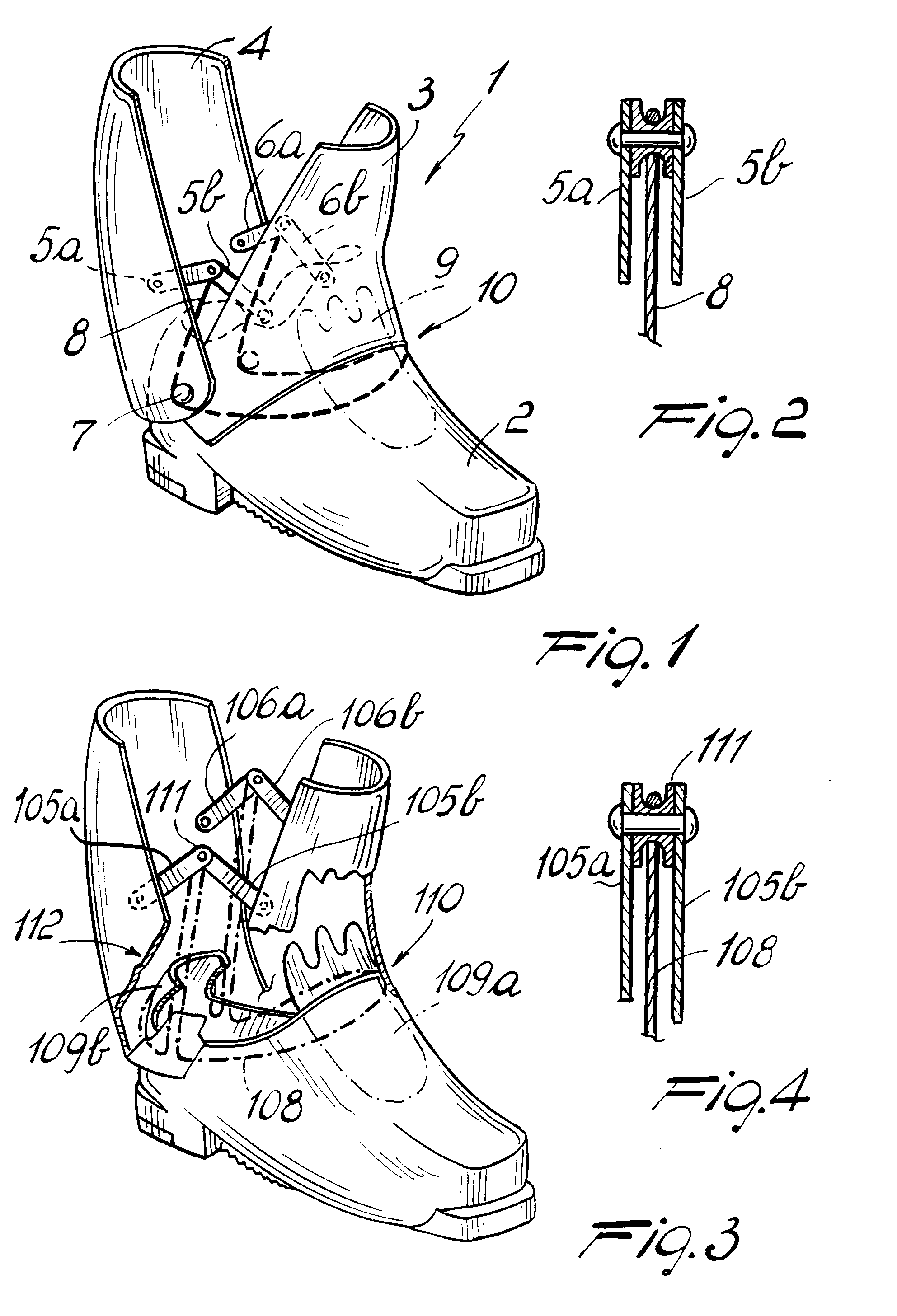
figure 1 is a partially sectioned perspective view of a boot according to the invention;
figure 2 is a cross section view taken at the articulation between two rod-like elements
of the boot of figure 1;
figure 3 is a view, similar to figure 1, of a boot according to another aspect of
the invention;
figure 4 is a view, similar to figure 2, related to the boot illustrated in figure
3;
figure 5 is a schematic perspective view of the interaction between the traction element
and the pairs of rod-like elements, related to the boot of figure 3;
figure 6 is a lateral elevation view of a boot according to a third aspect of the
invention;
figure 7 is a perspective view of a boot according to a fourth aspect.
[0027] With reference to figures 1 and 2, a ski boot, generally indicated by the reference
numeral 1, comprises a front quarter 3 and a rear quarter 4 associated to a shell
2.
[0028] The rear quarter 4 is pivoted to the shell 2 and is articulated to the front quarter
3 by means of two pairs of rods, indicated by the reference numerals 5a, 5b and 6a,
6b.
[0029] The rods 5a, 5b and 6a, 6b are articulated to one another in pairs at one end, and
are articulated at the other end respectively to the rear quarter 4 and to the front
quarter 3 above their pivoting stud 7.
[0030] Said rods are articulated at the related inner surfaces of said front quarter and
rear quarter or at the outer surface of the shell.
[0031] At the point of articulation between each of said two pairs or rods there is associated
therewith the end of a traction element constituted by a cable 8 guided to affect
a presser 9 arranged at the region 10 of the skier's foot instep.
[0032] The presser can be alternatively constituted by a flap associated with the shell
or with the inner shoe at the heel region, the cable acting in said region.
[0033] The operation of the device is as follows: as the rear quarter 4 approaches the front
quarter 3, correspondingly the articulation points of the rods 5a and 6a approach
the articulation points of the rods 5b and 6b.
[0034] This produces a lifting of the points of articulation between the pairs of rods 5a,
5b and 6a, 6b which stretches the cable 8, and said cable in turn secures the region
10 of the foot instep by exerting a pressure on the presser 9; the action can be alternatively
exerted on the heel.
[0035] Figure 3 illustrates a boot 101 wherein at the points of articulation between each
of the pairs of rods 105a, 105b and 106a, 106b there is rotatably interposed a pulley
111 at which the cable 108 is guided and is thus free to slide.
[0036] Said cable is thus guided to affect a presser 109a arranged at the foot instep region
110 and a presser 109b arranged at the foot heel region 112.
[0037] The simultaneous securing of the two regions 110 and 112 is thus achieved without
forcing the skier to actuate means for taking up the cable.
[0038] Figure 6 illustrates a further embodiment of the boot according to the invention,
wherein a single cable 208 is again used and affects both pulleys 211 interposed between
the mutually articulated ends of the two pairs of rods.
[0039] Only the rods 205a and 205b have been indicated for the sake of simplicity.
[0040] Said cable is rigidly associated at its ends internally to the rear quarter 204;
it subsequently affects a first guiding element 213 provided internally to the rear
quarter proximate to the stud 207, then the pulley 211, then a second guiding element
214 provided internally to the front quarter 203 and arranged facing the first guiding
element 213, then a third guiding element 215 again arranged internally to the front
quarter 203 proximate to its upper end 216.
[0041] The cable 208 finally affects a tensioning element such as a lever 217.
[0042] During the mutual approaching of the quarters there is an automatic takeup of a certain
portion of the cable 208 which in any case allows the securing of the quarters.
[0043] The fine adjustment and the subsequent tensioning can be performed by using the lever
217 or similar closure devices.
[0044] Naturally the cable can also be not rigidly associated with the rear quarter but
instead it can affect the region 212 of the heel and/or 210 of the instep of the foot.
[0045] Figure 7 illustrates another embodiment wherein four pairs of rods, indicated by
the reference numerals 305a, 305b, 305c, 305d and 306a, 306b, 306c, 306d, are articulated
to the front quarter 303 and to the rear quarter 304 and are mutually articulated
to form two diamonds, one for each side of the boot.
[0046] Each of the diamonds has two opposite vertices, one articulated to the front quarter
303 and the other to the rear quarter 304.
[0047] Pulleys 311a, 311b, 311c and 311d, are associated with the other two vertices.
[0048] The boot comprises a first cable 308a which is guided at the pulleys 311a and 311b
and at adapted guiding elements to affect the regions 310 and 312 respectively of
the instep and of the heel of the foot.
[0049] A second cable 308b interacts with an element for its tensioning such as a level
317 external to the boot, then it affects a first and a second guiding element, indicated
by the reference numerals 313 and 314, internal to the rear quarter 304, and finally
the pulleys 311c and 311d to be then rigidly associated internally to the front quarter
303.
[0050] The mutual approach of the quarters thus allows to simultaneously achieve their closure
and the optimum securing of the foot inside the boot.
[0051] Naturally the adjustment of the degree of opening and/or closure of the flap can
be obtained either by varying the length of at least one rod or by using a variable-length
rod or by varying the position of at least one articulation point.
[0052] It has thus been observed that the invention achieves the intended aim and objects,
a boot having been provided with a quarter opening system which is extremely functional
and compact and allows an easy introduction of the foot in particular because the
flap does not obstruct the opening. The movement which can be imparted to the flap,
during the quarter closure step, furthermore allows to achieve the optimum and rapid
securing of the heel.
1. Ski boot comprising a shell (2), a rear quarter (4;304), and a front quarter (3;303),
at least said rear quarter being pivoted to said shell, said ski boot further comprising
at least a pair of rod-like elements (5a,5b,6a,6b;105a,105b,106a,106b;305a-d,306a-d)
mutually pivoted at a pivot point (111;311a-d) and a traction element (8;108;308a,b)
interconnected between said pivot point and at least one foot presser (9;109a,109b;310,312)
of said boot, characterized in that the free ends of each of said pair of rod-like
elements are pivoted respectively: at the inner lateral surface of said rear quarter;
and at the inner lateral surface of said front quarter or at the outer lateral surface
of said shell, so that in the closed position of the rear quarter and the front quarter,
the rod-like elements are located internally of the ski boot.
2. Ski boot according to claim 1, characterized in that it comprises two pairs of said
rod-like elements (5a,5b and 6a,6b) each having one rod (5a,6a) pivoted to said rear
quarter (4) and another rod (5b,6b) pivoted to said shell (2), said traction element
(8) having its ends connected to the respective said pivot points of said two pair
of rod-like elements, said traction element extending from both sides of said pivot
points downwardly therefrom to engage a pair of opposite studs (7) which pivot said
rear quarter to said shell, said traction element extending forwardly from said studs
and engaging a foot instep presser (9).
3. Ski boot according to claim 1, characterized in that it comprises two pairs of said
rod-like elements (105a,105b and 106a,106b) each having one rod (105a,106a) pivoted
to said rear quarter and another rod (105b,106b) pivoted to said front quarter, a
pulley (111) being provided at each respective said pivot point of said two pairs
of rod-like elements, said traction element (108) extending in a loop and engaging
said pulleys and a foot instep presser (109a) and a heel presser (109b).
4. Ski boot according to claim 1, characterized in that to said front quarter (303) and
rear quarter (304) there are articulated four pairs of rods (305), mutually articulated
in pairs, to define a diamond-shaped configuration.
5. Ski boot according to claim 4, characterized in that said four pairs of rods (305)
have two mutually opposite vertices articulated to said inner lateral surfaces of
said front quarter (303) and rear quarter (304), pulleys (311) being associated at
the other two vertices.
6. Ski boot according to claim 4, characterized in that said four pairs of rods (305)
have two mutually opposite vertices articulated to said inner lateral surfaces of
said front quarter (303) and said rear quarter (304), pulleys (311) being associated
at the other two vertices, and furthermore comprising a first cable (308a), having
a loop-like configuration, which is guided at said pulleys, arranged at the vertex
of the diamond directed towards the upper end of said front quarter and said rear
quarter, and then at adapted guiding elements to affect the foot instep (310) and
heel (312) regions.
7. Ski boot according to claim 4, characterized in that said four pair of rods (305)
have two mutually opposite vertices articulated to said inner lateral surfaces of
said front quarter and said rear quarter, pulleys (311) being associated at the other
two vertices, and furthermore comprising a second cable (308b) which interacts with
an element for its tensioning, such as a lever (317) external to the boot, subsequently
affecting a first (313) and a second (314) guiding element internal to said rear quarter
(304), and finally affecting said pulleys (311c, 311d) arranged at the vertex of the
diamond oriented towards said pivoting stud to be then rigidly coupled internally
to said front quarter.
8. Ski boot comprising a shell (2), a rear quarter (204), and a front quarter (203),
at least said rear quarter being pivoted to said shell, said ski boot further comprising
at least a pair of rod-like elements (205a,205b) mutually pivoted at a pivot point
(211) and a traction element (208) interconnected between said pivot point and means
(217) for tensioning said traction element, characterized in that the free ends of
each of said pair of rod-like elements are pivoted respectively: at the inner lateral
surface of said rear quarter; and at the inner lateral surface of said front quarter
or at the outer lateral surface of said shell, so that in the closed position of the
rear quarter and the front quarter, the rod-like elements are located internally of
the ski boot, said means for tensioning being provided on one of said quarters and
said traction element extending therefrom and being slidable connected at a point
on the other of said quarters, thereby an actuation of said means for tensioning provides
a closing of said rear quarter to said front quarter.
9. Ski boot according to claim 8, characterized in that it comprises two pairs of said
rod-like elements (205a,205b) each having a pulley (211) interposed between the mutually
articulated ends thereof, said traction element having both of its ends connected
internally to said rear quarter (204), said traction element having a loop-like path
which is specular with respect to the middle plane longitudinal to said front quarter
(203) and rear quarter and which affects a first guiding element (213) arranged internally
to said rear quarter proximate to the stud (207) for pivoting to said front quarter,
then said pulley (211), subsequently a second guiding element (214) which is arranged
internally to said front quarter proximate to said pivoting stud, then a third guiding
element (215) arranged internally to said front quarter proximate to its upper end,
and finally which is connected to said means for tensioning said traction element
which comprises a tensioning lever (217) articulated to said rear quarter, wherein
the actuation of said tensioning lever provides a closing of said rear quarter to
said front quarter.
1. Skischuh, enthaltend eine Schale (2), einen hinteren Schaftteil (4; 304) und einen
vorderen Schaftteil (3; 303), wobei wenigstens der hintere Schaftteil schwenkbeweglich
an der Schale angeordnet ist, ferner enthält dieser Skischuh wenigstens ein Paar stangenartiger
Elemente (5a, 5b, 6a, 6b; 105a, 105b, 106a, 106b; 305a-d; 306a-d), die an einer Anlenkstelle
(111; 311a-d) gegenseitig schwenkbeweglich sind, und ein Zugelement (8; 108; 308a,
b), das zur Verbindung zwischen der genannten Anlenkstelle und wenigstens einem Fuß-Druckstück
(9; 109a, 109b; 310, 312) des Schuhes vorgesehen ist, dadurch gekennzeichnet, daß
die freien Enden jedes der genannten Paare von stangenartigen Elementen in entsprechender
Weise angelenkt sind: an der inneren Seitenflache des hinteren Schaftteiles sowie
an der inneren Seitenfläche des vorderen Schaftteiles oder an der äußeren Seitenfläche
der Schale, so daß in der geschlossenen Stellung des hinteren Schaftteiles und des
vorderen Schaftteiles die stangenartigen Elemente innerhalb des Skischuhes angeordnet
sind.
2. Skischuh nach Anspruch 1, dadurch gekennzeichnet, daß er zwei Paare von stangenartigen
Elementen (5a, 5b und 6a, 6b) enthält, von denen jedes eine Stange (5a, 6a), die am
hinteren Schaftteil (4) angelenkt ist, und eine weitere Stange (5b, 6b) aufweist,
die an der genannten Schale (2) angelenkt ist, wobei das Zugelement (8) an seinen
beiden Enden mit den entsprechenden Anlenkstellen der beiden Paare stangenartiger
Elemente verbunden ist, wobei dieses Zugelement sich von beiden Seiten dieser Anlenkstellen
aus nach unten erstreckt, um mit einem Paar gegenüberliegender Bolzen (7) in Eingriff
zu kommen, die den hinteren Schaftteil an der Schale anlenken, und wobei dieses Zugelement
sich von diesen Bolzen nach vorn erstreckt und mit einem Fußrist-Druckstück (9) in
Eingriff steht.
3. Skischuh nach Anspruch 1, dadurch gekennzeichnet, daß er zwei Paare von stangenartigen
Elementen (105a, 105b und 106a, 106b) enthält, von denen jedes eine Stange (105a,
106a), die am hinteren Schaftteil angelenkt ist, sowie eine weitere Stange (105b,
106b) enthält, die am vorderen Schaftteil angelenkt ist, wobei eine Seilscheibe (111)
an jeder entsprechenden Anlenkstelle der genannten Paare stangenartiger Elemente vorgesehen
ist, und wobei sich das genannte Zugelement (108) in einer Schlaufe erstreckt und
mit den genannten Seilscheiben und einem Fußrist-Druckstück (109a) und einem Fersendruckstück
(109b) in Eingriff steht.
4. Skischuh nach Anspruch 1, dadurch gekennzeichnet, daß an den vorderen Schaftteil (303)
und den hinteren Schaftteil (304) vier Paare von Stangen (305) angelenkt sind, die
gegenseitig in Paaren angelenkt sind, um eine rautenförmige Formgebung zu bilden.
5. Skischuh nach Anspruch 4, dadurch gekennzeichnet, daß die genannten vier Paare von
Stangen (305) zwei sich einander gegenüberliegende Scheitelpunkte aufweisen, die an
den inneren Seitenflächen des vorderen Schaftteiles (303) und hinteren Schaftteiles
(304) angelenkt sind, wobei Seilscheiben (311) mit den beiden anderen Scheitelpunkten
verbunden sind.
6. Skischuh nach Anspruch 4, dadurch gekennzeichnet, daß die genannten vier Paare von
Stangen (305) zwei sich wechselseitig gegenüberliegende Scheitelpunkte aufweisen,
die an den inneren Seitenflächen des vorderen Schaftteiles (303) und hinteren Schaftteiles
(304) angelenkt sind, wobei Seilscheiben (311) mit den beiden anderen Scheitelpunkten
verbunden sind, und daß er ferner ein erstes Kabel (308a) enthält, das eine schlaufenförmige
Formgebung aufweist und das an den genannten Seilscheiben, die am Scheitelpunkt der
Raute angeordnet sind, der auf das obere Ende des vorderen Schaftteiles und des hinteren
Schaftteiles gerichtet ist, und dann an angepaßten Führungselementen geführt ist,
um auf die Fußrist- und Fersenbereiche (310 bzw. 312) einzuwirken.
7. Skischuh nach Anspruch 4, dadurch gekennzeichnet, daß die vier Paare von Stangen (305)
zwei wechselseitig gegenüberliegende Scheitelpunkte aufweisen, die an den inneren
Seitenflächen des vorderen Schaftteiles und des hinteren Schaftteiles angelenkt sind,
wobei Seilscheiben (311) mit den beiden anderen Scheitelpunkten verbunden sind, und
daß er ferner ein zweites Kabel (308b) enthält, das mit einem Element für sein Anspannen,
z.B. einem Hebel (317), auf der Außenseite des Schuhes zusammenwirkt, danach auf ein
erstes (313) und ein zweites (314) Führungselement auf der Innenseite des hinteren
Schaftteiles (304) und schließlich auf die genannten Seilscheiben (311c, 311d) einwirkt,
die am Scheitelpunkt der Raute angeordnet sind, der in Richtung auf den Schwenkbolzen
orientiert ist, um dann im Innern mit dem vorderen Schaftteil starr verbunden zu werden.
8. Skischuh, enthaltend eine Schale (2), einen hinteren Schaftteil (204) und einen vorderen
Schaftteil (203), wobei wenigstens der hintere Schaftteil schwenkbeweglich an der
Schale angeordnet ist, ferner enthält dieser Skischuh wenigstens ein Paar stangenartiger
Elemente (205a, 205b), die wechselseitig an einer Anlenkstelle schwenkbeweglich sind,
und ein Zugelement (208), das zur Verbindung zwischen dieser Anlenkstelle und einer
Vorrichtung (217) zum Spannen dieses Zugelements vorgesehen ist, dadurch gekennzeichnet,
daß die freien Enden von jedem Paar der stangenförmigen Elemente in entsprechender
Weise angelenkt sind: an der inneren Seitenfläche des hinteren Schaftteiles und an
der inneren Seitenfläche des vorderen Schaftteiles oder an der äußeren Seitenfläche
der Schale, so daß in der geschlossenen Stellung des hinteren Schaftteiles und des
vorderen Schaftteiles die stangenartigen Elemente innerhalb des Skischuhes angeordnet
sind, wobei die genannte Vorrichtung zum Spannen an einem der genannten Schaftteile
vorgesehen ist und das Zugelement sich davon erstreckt und gleitbeweglich mit einer
Stelle am anderen Schaftteil verbunden ist, wodurch eine Betätigung der genannten
Spannvorrichtung ein Schließen des hinteren Schaftteiles gegenüber dem vorderen Schaftteil
schafft.
9. Skischuh nach Anspruch 8, dadurch gekennzeichnet, daß er zwei Paare von stangenartigen
Elementen (205a, 205b) enthält, von denen jedes eine Seilscheibe (211) aufweist, die
zwischen deren wechselseitig angelenkten Enden angeordnet sind, wobei das Zugelement
mit seinen beiden Enden innen mit dem hinteren Schaftteil (204) verbunden ist, wobei
dieses Zugelement einen schlaufenförmigen Weg aufweist, der in bezug auf die Mittelebene
in Längsrichtung zum vorderen Schaftteil (203) und hinteren Schaftteil spiegelbildlich
verläuft, und das auf ein erstes Führungselement (213), das innerhalb des hinteren
Schaftteiles in der Nähe des Bolzens (207) zum Schwenken des vorderen Schaftteiles
angeordnet ist, dann auf die Seilscheibe (211), danach auf ein zweites Führungselement
(214), das innerhalb des vorderen Schaftteiles in der Nähe des Schwenkbolzen angeordnet
ist, dann auf ein drittes Führungselement (215), das innerhalb des vorderen Schaftteiles
in der Nähe seines oberen Endes angeordnet ist, einwirkt und das schließlich mit der
genannten Vorrichtung zum Spannen dieses Zugelements verbunden ist, die einen Spannhebel
(217) enthält, der am hinteren Schaftteil angelenkt ist, wobei die Betätigung dieses
Spannhebels ein Schließen dieses hinteren Schaftteiles gegenüber dem vorderen Schaftteil
herbeiführt.
1. Chaussure de ski comprenant une coque (2), un quartier arrière (4; 304) et un quartier
avant (3; 303), ledit quartier arrière au moins étant monté de façon pivotante sur
ladite coque, ladite chaussure de ski comprenant en outre au moins une paire d'éléments
en forme de tige (5a, 5b, 6a, 6b; 105a, 105b, 106a, 106b; 305a-d, 306a-d) montés mutuellement
de façon pivotante en un point de pivotement (111; 311a-d) et un élément de traction
(8; 108; 308a-b) interconnecté entre ledit point de pivotement et au moins un élément
presseur de pied (9; 109a, 109b; 310, 312) de ladite chaussure, caractérisée en ce
que les extrémités libres de chacune desdites paires d'éléments en forme de tiges
sont montées respectivement de façon pivotante: sur la surface latérale interne dudit
quartier arrière; et sur la surface latérale interne dudit quartier avant ou sur la
surface latérale externe de ladite coque, de manière que dans la position fermée du
quartier arrière et du quartier avant, les éléments en forme de tiges soient situés
à l'intérieur de la chaussure de ski.
2. Chaussure de ski selon la revendication 1, caractérisée en ce qu'elle comprend deux
paires desdits éléments en forme de tiges (5a, 5b et 6a, 6b) comprenant chacune une
tige (5a, 6a) montée de façon pivotante sur ledit quartier arrière (4) et une autre
tige (5b, 6b) montée de façon pivotante sur ladite coque (2), ledit élément de traction
(8) ayant ses extrémités reliées auxdits points de pivotement respectifs desdites
deux paires d'éléments en forme de tiges, ledit élément de traction s'étendant à partir
des deux côtés desdits points de pivotement vers le bas de ceux-ci pour venir en engagement
avec une paire de tenons opposés (7) qui permettent le pivotement dudit quartier arrière
par rapport à ladite coque, ledit élément de traction s'étendant vers l'avant à partir
desdits tenons et venant en engagement avec un élément presseur de cou-de-pied (9).
3. Chaussure de ski selon la revendication 1, caractérisée en ce qu'elle comprend deux
paires desdits éléments en forme de tiges (105a, 105b et 106a, 106b) comprenant chacun
une tige (105a, 106a) montée de façon pivotante sur ledit quartier arrière et une
autre tige (105b, 106b) montée de façon pivotante sur ledit quartier avant, une poulie
(111) étant prévue en chacun desdits points de pivotement respectifs desdites deux
paires d'éléments en forme de tiges, lesdits éléments de traction (108) s'étendant
sous forme d'une boucle et venant en engagement avec lesdites poulies et un élément
presseur de cou-de-pied (109a) et un élément presseur de talon (109b).
4. Chaussure de ski selon la revendication 1, caractérisée en ce que quatre paires de
tiges (305) mutuellement articulées par paires pour définir une configuration en forme
de losange sont articulées sur ledit quartier avant (303) et ledit quartier arrière
(304).
5. Chaussure de ski selon la revendication 4, caractérisée en ce que lesdites quatre
paires de tiges (305) comprennent deux sommets mutuellement opposés et articulés auxdites
surfaces latérales internes dudit quartier avant (303) et dudit quartier arrière (304),
des poulies (311) étant associées aux deux autres sommets.
6. Chaussure de ski selon la revendication 4, caractérisée en ce que lesdites quatre
paires de tiges (305) comprennent deux sommets mutuellement opposés articulés auxdites
surfaces latérales internes dudit quartier avant (303) et dudit quartier arrière (304),
des poulies (311) étant associées aux deux autres sommets, et comprenant en outre
un premier câble (308a), à configuration en forme de boucle, qui est guidé sur lesdites
poulies disposées au sommet du losange qui est tourné vers l'extrémité supérieure
dudit quartier avant et dudit quartier arrière, et ensuite sur des éléments de guidage
adaptés pour affecter les régions du cou-de-pied (310) et du talon (312).
7. Chaussure de ski selon la revendication 4, caractérisée en ce que lesdites quatre
paires de tiges (305) comprennent des sommets mutuellement opposés articulés auxdites
surfaces latérales internes dudit quartier avant et dudit quartier arrière, des poulies
(311) étant associées aux deux autres sommets, et comprenant en outre un second câble
(308b) qui coopère avec un élément pour sa mise en tension, tel qu'un levier (317)
qui est extérieur à la chaussure, et passant ensuite sur un premier (313) et un second
(314) éléments de guidage internes audit quartier arrière (304) et finalement sur
lesdites poulies (331c, 311d) disposées au sommet du losange orienté en direction
dudit tenon de pivotement pour être ensuite accouplé rigidement à l'intérieur dudit
quartier avant.
8. Chaussure de ski comprenant une coque (2), un quartier arrière (204) et un quartier
avant (203), ledit quartier arrière au moins étant monté de façon pivotante sur ladite
coque, ladite chaussure de ski comprenant en outre au moins une paire d'éléments en
forme de tiges (205a, 205b) montées de façon mutuellement pivotante en un point de
pivotement (211) et un élément de traction (208) interconnecté entre lesdits points
de pivotement et des moyens (217) pour mettre en tension ledit élément de traction,
caractérisée en ce que les extrémités libres de chacun de ladite paire d'éléments
en forme de tiges sont respectivement montées de façon pivotante: sur la surface latérale
interne dudit quartier arrière; et sur la surface latérale interne dudit quartier
avant ou sur la surface latérale externe de ladite coque, de manière que dans la position
fermée du quartier arrière et du quartier avant, les éléments en forme de tiges soient
situés à l'intérieur de la chaussure de ski, lesdits moyens de mise en tension étant
prévus sur l'un desdits quartiers arrière et ledit élément de traction s'étendant
à partir de celui-ci et étant relié de façon coulissante en un point sur l'autre desdits
quartiers, un actionnement desdits moyens de mise en tension déterminant la fermeture
dudit quartier arrière par rapport audit quartier avant.
9. Chaussure de ski selon la revendication 8, caractérisée en ce qu'elle comprend deux
paires desdits éléments en forme de tiges (205a, 205b) comprenant chacune une poulie
(211) interposée entre leurs extrémités mutuellement articulées, ledit élément de
traction ayant ses deux extrémités reliées à l'intérieur dudit quartier arrière (204),
ledit élément de traction suivant un parcours en forme de boucle qui est symétrique
par rapport au plan longitudinal central dudit quartier avant (203) et dudit quartier
arrière et qui passe sur un premier élément de guidage (213) disposé à l'intérieur
dudit quartier arrière à proximité du tenon (207) lui permettant de pivoter par rapport
audit quartier avant, puis sur ladite poulie (211), et ensuite sur un second élément
de guidage (214) qui est disposé à l'intérieur dudit quartier avant à proximité dudit
tenon de pivotement, puis sur un troisième élément de guidage (215) disposé à l'intérieur
dudit quartier avant à proximité de son extrémité supérieure, et est finalement relié
auxdits moyens de mise en tension dudit élément de traction qui comprennent un levier
tendeur (217) articulé sur ledit quartier arrière, l'actionnement dudit levier tendeur
déterminant la fermeture dudit quartier arrière par rapport audit quartier avant.