| (19) |
 |
|
(11) |
EP 0 310 569 B1 |
| (12) |
EUROPEAN PATENT SPECIFICATION |
| (45) |
Mention of the grant of the patent: |
|
22.04.1992 Bulletin 1992/17 |
| (22) |
Date of filing: 19.07.1988 |
|
| (51) |
International Patent Classification (IPC)5: B05B 11/04 |
|
| (54) |
Metering device to be applied on flexible wall bottles and the like and adapted to
nebulize the metered liquid
Für das Sprühen passend gemachte Dosiervorrichtung für Quetschflaschen
Dispositif de dosage pour bouteilles à parois flexibles adapté à la nébulisation d'un
liquide dosé
|
| (84) |
Designated Contracting States: |
|
AT BE CH DE ES FR GB GR LI LU NL SE |
| (30) |
Priority: |
24.09.1987 IT 2241787 U
|
| (43) |
Date of publication of application: |
|
05.04.1989 Bulletin 1989/14 |
| (73) |
Proprietor: PLASTIAPE S.p.A. |
|
22058 Osnago (Como) (IT) |
|
| (72) |
Inventor: |
|
- Citterio, Gian Franco
Plastiape S.p.A.
I-22058 Osnago (IT)
|
| (74) |
Representative: Cicogna, Franco |
|
Ufficio Internazionale Brevetti
Dott.Prof. Franco Cicogna
Via Visconti di Modrone, 14/A
20122 Milano
20122 Milano (IT) |
| (56) |
References cited: :
US-A- 2 573 731
US-A- 3 519 208
|
US-A- 3 014 666
US-A- 4 530 466
|
|
| |
|
|
|
|
| |
|
| Note: Within nine months from the publication of the mention of the grant of the European
patent, any person may give notice to the European Patent Office of opposition to
the European patent
granted. Notice of opposition shall be filed in a written reasoned statement. It shall
not be deemed to
have been filed until the opposition fee has been paid. (Art. 99(1) European Patent
Convention).
|
BACKGROUND OF THE INVENTION
[0001] The present invention relates to a metering device to be applied to bottles and the
like, having flexible walls and being adapted to nebulize the supplied liquid. Such
devices are described in US-A- 2 573 731 and US-A- 4 530 466.
[0002] As is known,liquid must be sometimes supplied in nebulized form, that is as very
small droplets dispersed within a gaseous phase.
[0003] Also known is the fact that nebulizing devices are presently available which,however,have
a rather complex structure which negatively affects the cost of the nebulizing device
and requires frequent maintenance and replacement operations.
SUMMARY OF THE INVENTION
[0004] Accordingly, the task of the present invention is to overcome the above mentioned
drawbacks by providing such a nebulizing device, to be applied to flexible bottles
and the like,which is very simple construction-wise and has a very reduced cost.
[0005] Within the scope of the above mentioned task, a main object of the present invention
is to provide such a neublizing device which comprises a very reduced number of component
parts and which is very reliable in operation.
[0006] Another object of the present invention is to provide such a nebulizing device which
is devoid of any wearable movable parts.
[0007] According to one aspect of the present invention the above mentioned task and objects,as
well as yet other objects,which will become more apparent hereinafter,are achieved
by a nebulizing device, to be applied to flexible wall bottles and the like, characterized
in that said nebulizing device comprises a plug member,adapted to operate as a reducing
member and provided,at its axis, with a tubular member ending with a top nozzle and
provided, on the inner surface of its wall,with longitudinal ridges formed at symmetric
positions,within said tubular member there being arranged an elongate structure fitted
at the end of a small tube immersed in the vessel of the liquid to be nebulized, the
structure having longitudinal slots and being provided with a shaped head adapted
to operate as a vortex generating member to intimately mix said liquid and the air
sucked therewith.
[0008] The dependent claims comprise further embodiments of the nebulizing device.
BRIEF DESCRIPTION OF THE DRAWINGS
[0009] Further characteristics and advantages of the neublizing device according to the
present invention will become more apparent hereinafter from the following detailed
description of a preferred embodiment thereof which is illustrated,by way of an indicative
but not limitative example,in the figures of the accompanying drawings,where:
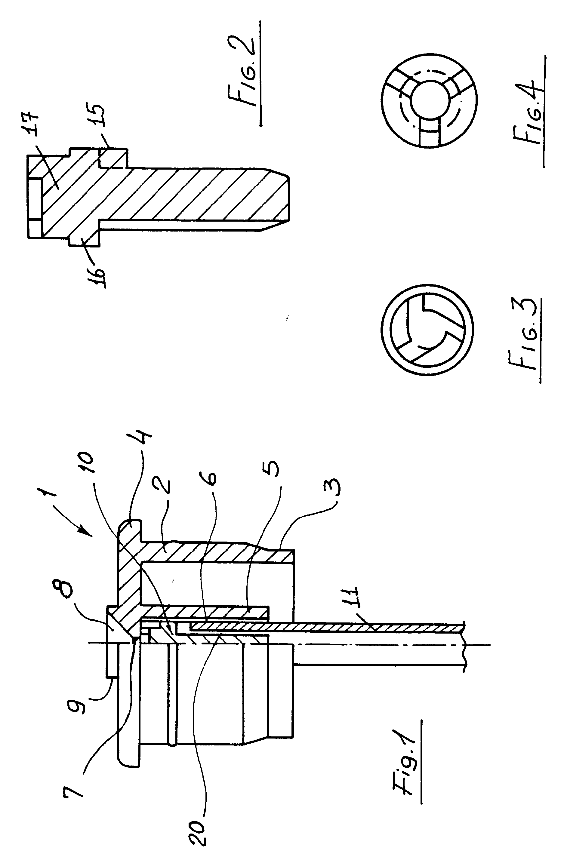
figure 1 is a partial cross-sectional view illustrating the nebulizing device according
to the present invention; and
figures 2,3 and 4 are respectively a side view and two cross-sectional top views illustrating
the vortex generating member included in the nebulizing device according to the present
invention.
DESCRIPTION OF THE PREFERRED EMBODIMENT
[0010] With reference to the figures of the accompanying drawings,the nebulizing device,
to be applied to flexible bottle and the like according to the present invention,comprises
a plug member, indicated at the reference number 1,and adapted to operate as a reducing
member.
[0011] This plug member,in particular,consists of a box-like body (2) having a shape and
size which depend on those of the mouth of the vessel thereon said plug member must
be applied,and being provided with a tapering bottom portion 3 and a top projecting
edge 4.
[0012] The plug member is coaxially provided with a tubular member 5 which is provided,at
the inner face of its wall,with longitudinal ridges which are formed at preferably
symmetric positions and are adapted to define corresponding slotted longitudinal portions
6.
[0013] The tubular member ends with a top nozzle 7 opening on a frustum of cone shaped cavity
8 which is formed on a projecting round portion 9 provided at the center of the mentioned
box-like body,at said tubular member.
[0014] Inside the tubular member there is provided an elongate structure,indicated overally
at the reference number 10,which is in turn fitted at the top of a small tube 11 immersed
in the vessel of the liquid to be nebulized.
[0015] The mentioned elongate structure essentially consists of a stem 12 ending,at the
bottom thereof, with a preferably ogival portion 13, and being provided with longitudinal
ridges 14 having a top abutment 15 adapted to engage on the edge of the mentioned
small tube.
[0016] At its top portion the stem bears a cylindrical portion 16 thereabove a disk member
17 is arranged said disk member being provided with discontinuous perimetrical ridges
18 defining corresponding slots 19 which are arranged on the extensions of the longitudinal
ridges 14.
[0017] The mentioned cylindrical portion,in particular, has a cross-section which depends
on that of the tubular member 5 so as it is engaged by friction in said tubular member.
[0018] Owing to the mentioned constructional features, as the flexible walls of the vessel
or bottle containing the liquid to be nebulized are pressed, the liquid will flow
along the stem 12, through the gaps 20 defined by the ridges 14.
[0019] Contemporaneously,air will flow upwardly along the gaps 6 and will be mixed with
the liquid so as to arrive at the bottom of the mentioned disc like member 17.
[0020] Then the liquid-air mixture will enter,through the slots 19,the chamber defined by
the ridges 18, thereby the inlet flows will impact to break the liquid to be nebulizing
into a lot of very small droplets which will be ejected through the mentioned nozzle
7.
[0021] From the above disclosure it should be apparent that the invention fully achieves
the intended task and objects.
1. A nebulizing device, to be applied to flexible wall bottles and the like, characterized
in that said nebulizing device comprises a plug member (1), adapted to operate as
a reducing member and provided, at its axis, with a tubular member (5) ending with
a top nozzle (7) and being provided,on the inner surface of its wall, with longitudinal
ridges formed at symmetric positions, within said tubular member there being arranged
an elongate structure (10) fitted at the end of a small tube (11) immersed in the
bottle or vessel of the liquid to be nebulized, the structure having longitudinal
slots and being provided with a shaped head adapted to operate as a vortex generating
member to intimately mix said liquid and the air sucked therewith.
2. A nebulizing device according to the preceding claim, characterized in that said
plug member consists of a box-like body (2) having a shape and size depending on those
of the mouth of said vessel or bottle thereon said nebulizing device must be applied
and being provided with a bottom tapering portion (3) and a top projecting edge (4)
said longitudinal ridges formed on the inner face of said tubular member defining
slotted portions (6).
3. A nebulizing device according to the preceding claims,characterized in that said
tubular member (5) ends with the top nozzle (7) opening on a frustum of cone shaped
cavity (8), provided in a projecting round portion (9) arranged at the center of said
box-like body,at said tubular member (5), the elongate structure (10) being moreover
provided fitted inside said tubular member.
4. A nebulizing device according to one or more of the preceding claims,characterized
in that said elongate structure (10) essentially consists of a stem ending,at the
bottom thereof,with an ogival portion and being provided with longitudinal ridges
having a top abutment (15) adapted to be engaged on the edge of said small tube,said
stem supporting,on the top thereof, a cylindrical portion (16) thereabove a disc like
member (17) is arranged,said disc like member being provided with discontinuous perimetrical
ridges defining corresponding slots arranged on the extensions of said longitudinal
ridges.
5. A nebulizing device according to one or more of the preceding claims,characterized
in that said cylindrical portion (16) has a cross section which depends on the cross
section of said tubular member (5) coaxial with said box-like structure so as to be
engaged by friction with said tubular member.
1. Sprühvorrichtung für Quetschflaschen und dergleichen, dadurch gekennzeichnet, daß
diese Sprühvorrichtung mit einem als Reduzierelement wirkenden Stopfen (1) vorgesehen
ist, der an seiner Achse, mit einem mit einer Oberdüse (7) endenden röhrenförmigen
Element (5) und an der inneren Fläche seiner Seite mit symmetrisch angeordneten Längsrippen
vorgesehen ist, wobei innerhalb dem obengenannten röhrenförmigen Element eine verlängerte
Struktur (10) angeordnet ist, die am Ende des obengenannten Röhrchens angepasst wird,
das in der Flasche oder dem Behälter des zusprühenden Flussiges eingetaucht ist, wobei
diese Struktur mit Längsschlitzen vorgesehen ist und einen geforte Kopf, der zum Betreiben
als wirbelerzeugenden Element um den obengenannte Flüssig und den mit demselben gesaugten
Luft zu mischen geeignet ist, weist auf.
2. Sprühvorrichtung nach vorhergehendem Anspruch, dadurch gekennzeichnet, daß dies
Stopfenelement aus einem Kastenkörper (2) besteht, dessen Gestalt und Maß dem Gestalt
und Maß der Flasche oder des Behälters auf den die obengenannte Sprühvorrichtung angebracht
werden muß, abhängt, und wobei dieser Körper eine am. Ende sich verjüngende Portion
(3) und eine vorspringende Kante (4) weist auf, wobei diese auf die innere Seite des
obengenannten röhrenförmigen Elementes gebildeten Längskanten, geschlitzteten Portionen
(6) bestimmen.
3. Sprühvorrichtung nach vorhergehenden Ansprüchen, dadurch gekennzeichnet, daß dies
röhrenförmigen Element (5) mit der auf eine kegelstumpfförmige Aushöhlung (8) sich
öffenden Oberdüse (7) endet, wo diese Aushöhlung, in einer vorspringenden rundförmigen
Portion (9), die inmitten des obengenannten Kastenkörper angeordnet ist, auf den obengenannte
Röhrenförmige Element (5) vorgesehen ist, wobei die verlängerte Struktur (10), außerdem,
innerhalb dem obengenannten röhrenförmigen Element eingefügt ist.
4. Sprühvorrichtung nach einem oder mehreren der vorhergehenden Ansprüchen, dadurch
gekennzeichnet, daß die obengenannte verlängerte Struktur (10) wesentlich aus einer
Spindel besteht, die am Boden derselben Struktur mit einem ogivalen Teil endet und
mit Längsrillen vorgesehen ist, die einen obere Berührungspunkt (15) zur Anpassung
auf die Kante des obengenannten Röhrchens weist auf, wobei diese Spindel auf seinen
obere Teil eine zylindrische Portion (16) stützt, auf die ein scheibenförmiges Element
(17) angeordnet ist, wobei dies Scheibenelement mit unterbrochenen Umlaufsrillen vorgesehen
ist, die die auf den Erstreckungen der obengenannten Längsrillen entsprechend angeordneten
Schlitze bestimmen.
5. Sprühvorrichtung nach einem oder mehreren der vorhergehenden Ansprüchen, dadurch
gekennzeichnet, daß die obengenannte zylindrische Portion (16) einen Querschnitt weist
auf, der aus dem Querschnitt des obengenannten röhrenförmigen Elementes (5) abhängt,
das coaxial mit der obengenannten kastenförmigen Struktur ist, um so durch Reibung
mit dem obengenannten röhrenförmigen Element engagiert wird.
1. Dispositif nébulisateur à être appliqué sur bouteilles à parois flexibles et similaires,
caractérisé en ce que ledit dispositif nébulisateur comprend un élément bouchon (1)
apte à faire fonction d'élément réducteur et muni, sur son axe, d'un élément tubulaire
(5) se terminant par une buse supérieure (7), et étant pourvu, sur la surface intérieure
de sa paroi, de nervures longitudinales formées dans positions symétriques, à l'intérieur
dudit élément tubulaire il y étant prévu une structure allongée (10) arrangée à l'extrémité
d'un petit tube (11) plongé dans la bouteille ou le vaisseau du liquide à être nébulisé,
ladite structure présentant des fentes longitudinales et étant munie d'une tête façonnée
apte à faire fonction d'élément générateur de tourbillon pour mélanger intimement
ledit liquide et l'air aspiré par cela.
2. Dispositif nébulisateur selon la revendication précédente, caractérisé en ce que
ledit élément-bouchon se forme d'un corps (2) en forme de boîte présentant une forme
et une mesure dépendant de celles de la bouche dudit vaisseau ou de la bouteille sur
laquelle ledit dispositif nébulisateur doit être appliqué, et étant muni d'une portion
s'éffilant au fond (3) et d'un bord supérieur (4) saillant, lesdites nervures longitudinales
formées sur la face intérieure dudit élément tubulaire définant des portions fendillées.(6).
3. Dispositif nébulisateur selon les revendications précédentes, caractérisé en ce
que ledit élément tubulaire (5) se termine par une buse supérieure (7) s'ouvrant sur
une cavité en forme de tronc de cône (8) prévue dans une portion (9) arrondie saillante,
arrangée au milieu dudit corps en forme de boîte, sur ledit élément tubulaire (5),
ladite structure allongée (10) étant prévue en outre arrangée à l'intérieur dudit
élément tubulaire.
4. Dispositif nébulisateur selon l'une ou plusieurs des revendications précédentes,
caractérisé en ce que ladite structure allongée (10) se forme essentiellement d'un
fuseau se terminant, sur son fond, par une portion ogivale et étant munie de nervures
longitudinales présentant un about (15) apte à être engagé sur le bord dudit petit
tube, ledit fuseau supportant, en haut, une portion cylindrique (16) sur laquelle
il y a arrangé un élément en forme de disque (17), ledit élément en forme de disque
étant muni de nervures périmétrales discontinues définant des fentes correspondantes
arrangées sur l'extension desdites nervures longitudinales.
5. Dispositif nébulisateur selon l'une ou plusieurs des revendications précédentes,
caractérisé en ce que ladite portion cylindrique (16) présente une section transversale
dépendant de la section transversale dudit élément tubulaire (5), coaxial avec ladite
structure en forme de boîte, de façon d'être engagée par friction avec ledit élément
tubulaire.