| (19) |
 |
|
(11) |
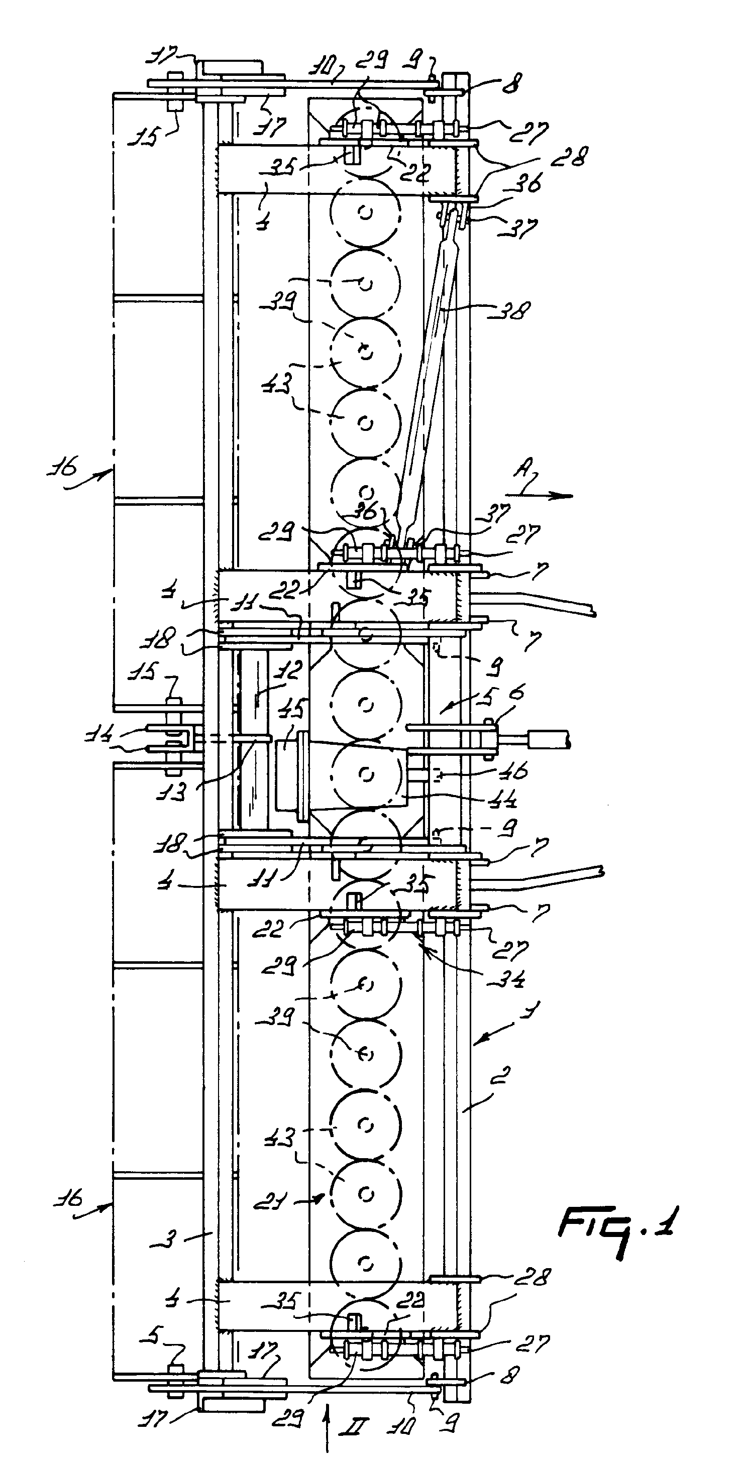
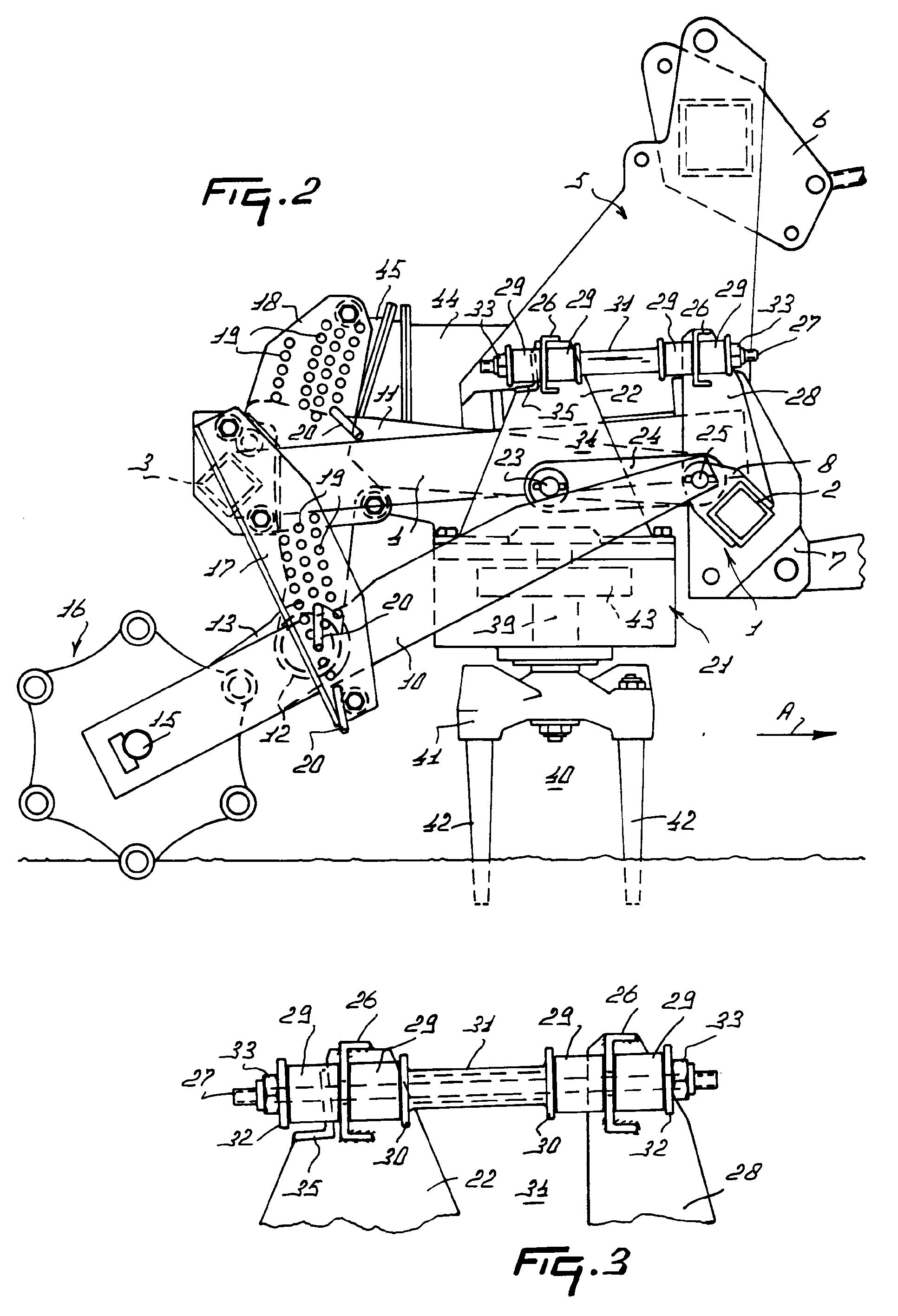
EP 0 321 031 B1 |
| (12) |
EUROPEAN PATENT SPECIFICATION |
| (45) |
Mention of the grant of the patent: |
|
04.03.1992 Bulletin 1992/10 |
| (22) |
Date of filing: 09.12.1988 |
|
|
| (54) |
A soil cultivating machine
Bodenbearbeitungsmaschine
Machine pour travailler le sol
|
| (84) |
Designated Contracting States: |
|
DE FR GB NL |
| (30) |
Priority: |
14.12.1987 NL 8703013
|
| (43) |
Date of publication of application: |
|
21.06.1989 Bulletin 1989/25 |
| (73) |
Proprietor: C. van der Lely N.V. |
|
NL-3155 PD Maasland (NL) |
|
| (72) |
Inventors: |
|
- Bom, Cornelis Johannes Gerardus
Rozenburg (NL)
- Kuipers, Arie
Harlingen (NL)
|
| (74) |
Representative: Mulder, Herman et al |
|
Octrooibureau Van der Lely N.V.
Weverskade 10
3155 PD Maasland
3155 PD Maasland (NL) |
| (56) |
References cited: :
DD-A- 100 131
DE-A- 2 755 001
DE-A- 3 504 654
DE-C- 420 963
DE-U- 1 985 782
FR-A- 1 114 553
FR-A- 2 330 296
US-A- 3 559 744
|
DD-A- 203 807
DE-A- 2 841 468
DE-B- 2 552 810
DE-C- 443 219
DE-U- 1 989 609
FR-A- 1 122 656
FR-A- 2 404 381
US-A- 4 142 587
|
|
| |
|
|
- Dubbels Taschenbuch für den Maschinenbau, Springer-Verlag 1953, Erster Band, pages
238,239
|
|
| |
|
| Note: Within nine months from the publication of the mention of the grant of the European
patent, any person may give notice to the European Patent Office of opposition to
the European patent
granted. Notice of opposition shall be filed in a written reasoned statement. It shall
not be deemed to
have been filed until the opposition fee has been paid. (Art. 99(1) European Patent
Convention).
|
[0001] The invention relates to a soil cultivating machine comprising a carrier frame which
can be coupled to a tractor and to which by means of pivotal connections there is
attached a frame portion that is movable in height and carries a plurality of drivable
soil working members arranged in side-by-side relationship in a row transversely to
the direction of operative travel, the said pivotal connections including a pivotal
polygon.
[0002] In soil cultivating machines of the above-defined type, which are known e.g. from
DE-OS 35 04 654, the frame portion can deflect upwardly by means of the pivotal connections
when the soil working members hit obstacles in the soil. However, with this construction
it may happen that, due to its pivotal support, the frame portion is not always adequately
stable during operation, thereby disadvantageously influencing the action of the soil
working members.
[0003] Using the construction according to the invention, this disadvantage can be eliminated
by designing at least one side of the pivotal polygon elastically deformably. Using
this construction, it is possible to obtain a compact pivotal connection which, during
operation, significantly increases the stability of the frame portion and nevertheless,
if so required, allows of a quick movement thereof.
[0004] For a better understanding of the invention and to show how the same may be carried
into effect, reference will now be made, by way of example, to an embodiment shown
in the accompanying drawings, wherein:
Figure 1 is a plan view of a soil cultivating machine comprising a construction according
to the invention;
Figure 2 is, to an enlarged scale, a view taken in the direction of the arrow II in
Figure 1, and
Figure 3 shows, to an enlarged scale, part of a pivotal polygon including the construction
in accordance with the invention.
[0005] The implement shown in the drawings concerns a soil cultivating machine, in particular
one for the preparation of a seedbed, which machine comprises a carrier frame 1 extending
transversely to the direction of operative travel A. The carrier frame 1 is assembled
from two frame beams 2 and 3, which beams are arranged at some interspace behind each
other and extend at least substantially horizontally and transversely to the direction
of operative travel A. Near their ends and on both sides of the mid-way point at equal
distance therefrom, the frame beams 2 and 3 are interconnected by means of supports
4 which extend in the direction of operative travel A. At the facing sides of the
centre supports 4 there are connected the upwardly extending legs of a trestle 5,
which legs are also mounted on the front frame beam 2. At its upper side, the trestle
5 is provided with a coupling point 6 for the upper arm of the three-point lifting
hitch of a tractor, while on both sides of the supports 4 the front frame beam 2 is
provided with pairs of plates, each of which constitutes a coupling point 7 for the
lower arms of the three-point lifting hitch of a tractor. At the ends and near the
facing sides of the centre supports 4, the frame beam 2 is provided at its rear side
with lugs 8 to which is connected a pin 9 that extends transversely to the direction
of operative travel A, the arrangement being such that the respective pins 9 are in
alignment (Figure 1). Around the outer pins 9 there are arranged freely pivotably
arms 10 which extend rearwardly. Around the pins 9 located near the centre supports
4 there are pivotal arms 11, which arms constitute part of a carrier frame which furthermore
includes a cross-beam 12, the said cross-beam being arranged between downwardly directed
portions of the arms 11. Near its mid-way point, the cross-beam 12 is provided with
an obliquely rearwardly and downwardly extending support 13 which terminates in a
fork 14. The legs of the fork 14 are fitted with pins 15 which extend transversely
to the direction of operative travel A and at least substantially horizontally, with
the aid of which pins an end of two aligned rollers 16 is supported freely rotatably.
At their other ends, the rollers 16 are also supported freely rotatably by a pin 15
fitted to an arm 10 and located in alignment with said former pins 15.
[0006] Each of the outer arms 10 for the rollers 16 is arranged capably of movement in height
between two plates 17 which extend obliquely downwardly and forwardly from one end
of the frame beam 3, while each of the arms 11 is movable between two interspaced
plates 18 connected to the forwardly directed side of the frame beam 3. Each of the
respective plates 17 and 18 is provided with three rows of apertures 19, which rows
are arranged behind each other, extend upwardly and are located on the arc of a circle
having its centre point on the longitudinal centre line of the respective pivot pins
9 for the arms 10 and 11; the configuration of the apertures in the respective rows
is shown in Figure 2. By means of pins 20 bearing on the upper side of the respective
arms 10 and 11, the position of the rollers 16 can be adjusted relative to the carrier
frame 1. With the aid of a pin 20 to be arranged at the bottom sides of the outer
arms 10, the position of the outer arms is then fixed. During operation, this provides
a certain degree of flexibility for the rollers at their facing sides, which at a
working width of 4.5 m, i.e. the working width of the machine in accordance with the
embodiment, may be desirable. At the rear sides of the arms 11 there is a stop which,
during transport, prevents excessive downward movement by contacting the upper side
of the frame beam 3. As is apparent from Figure 1, between the frame beams 2 and 3
of the carrier frame 1 there is arranged a box-like frame portion 21 of rectangular
cross-section (Figure 2). At its upper side, the frame portion 21 is provided with
upwardly directed supporting plates 22 which are arranged such that they contact the
outer sides of the supports 4 (Figure 1). As is apparent from Figure 2, the supporting
plates 22 are triangular in shape, their bases being fitted to the upper side of the
frame portion 21. Near its mid-way point at some distance above the frame portion
21, each supporting plate 22 is provided with an at least substantially horizontal
pin 23 which extends transversely to the direction of operative travel A and is surrounded
by a forwardly extending arm 24. The leading end of the arm 24 is arranged freely
pivotably on the frame beam 2 by means of a pin 25 extending parallel to the pin 23.
The upper side of each supporting plate 22 is fitted with an U-shaped support 26 having
forwardly extending legs. Through that portion of the U-shaped portion 26 that is
located between the legs there is passed with some clearance an arm 27 in the form
of a rod, which arm is also passed with some clearance through the portion between
the legs of an identically arranged support 26 on an upwardly extending plate 28 mounted
on the upper side of the frame beam 2 (Figure 3).
[0007] On both sides of the U-shaped supports 26, the rod 27 is enveloped by a cylindrical
buffer 29 made of a flexible material, preferably rubber. The buffers 29 located at
the inner sides of the U-shaped supports 26 are enclosed between the U-shaped supports
and stops 30 arranged at the ends of a bushing 31, which bushing is slidable over
the rod (Figure 3). The outermost buffers 29 are arranged between the U-shaped supports
26 and stops 32 on the rod 27, which stops 32 are movable by means of nuts 33 adapted
to co-operate with thread on the ends of the rod. By means of the adjustable stops
32, the reaction force counteracting a pivotal movement can be increased ordec- reased.
The arm 24 and the rod 27 constitute a pivotal polygon 34 in the shape of a parallelogram.
By means of the flexible buffers 29 and the clearance in the passage for the rod 27
there are created imaginary pivot points, the said buffers counteracting a pivotal
movement of the polygon. At their rear sides, each supporting plate 22 is provided
in the region of the upper arm 27 of the polygon 34, formed by the rod, with a stop
35 which extends transversely and is adapted to co-operate with the upper side of
a support 4, the arrangement being such that, during transport, the frame portion
21 cannot move too far downwards. Between the outermost supporting plate 22 on the
frame portion 21 that, taken in the direction of operative travel A of the machine,
is the left-hand one and a supporting plate 22 arranged near the mid-way point on
the frame portion 1 there is fitted a stabilizer rod 38 by means of lugs 36 and pins
37. Inside the frame portion 21 there are supported at equal interspaces of preferably
25 cms the upwardly directed, preferably vertical, shafts 39 of soil working members
40. Each of the soil working members 40 includes a carrier 41 which is provided on
the end of a shaft 39 projecting from the bottom side of the frame portion 21 and
near its ends is provided with downwardly extending soil working elements 42 constituted
by tines. Inside the box-like frame portion 21, each shaft 39 is provided with a pinion
43, the arrangement being such that the pinions on the shafts of adjacent soil working
members 40 are in driving connection with each other. Near the centre of the frame
portion 21, the shaft 39 of a soil working member 40 is extended upwardly and reaches
by means of this extension to into a gear box 44, inside which this shaft is in driving
connection via a bevel gear transmission with a shaft extending in the direction of
operative travel A. Via a speed variator 45 located at the rear side of the gear box,
the relevant shaft is in driving connection with a shaft 46 which extends in the direction
of operative travel A and projects from the gear box at the front side.
[0008] The machines as described in the foregoing operates as follows:
During operation, the machine is connected by means of the coupling points 6 and 7
to the upper and lower arms, respectively, of the lifting hitch of a tractor and the
soil working members 40 can be driven such from the power take-off shaft of the tractor
via an intermediate shaft and the above-described transmission that two adjacent soil
working members rotate in opposite directions (Figure 1), whereby by means of their
soil working elements 42 they cultivate at least contiguous strips of soil. The working
depth of the soil working members 40 can be set by means of the aligned rollers 16
with the aid of the pins 20 and the apertures 19 arranged in the respective pairs
of plates 17 and 18. During operation, the frame portion 21 carrying the soil working
members 40 is maintained in a position as shown in Figure 2 by means of the pivotal
polygons 34 in the form of parallelograms, and, as has been described in the foregoing,
the rollers determine the working depth. Using the polygons 34 in accordance with
the invention, at least one side of the pivotal polygon is elastically deformable
owing to the fact that the upper imaginary pivot points formed by the respective feed-through
points of the rod 27 through the supports 26 are elastically movable. This provides
an adequate stability of the frame portion 21 carrying the soil working members 40.
When one or more soil working members 40 hits/hit hard objects, e.g. stones, a quick
upward deflection of the frame portion 21 carrying the soil working members is nevertheless
possible, the assembly being rapidly returned to its initial position after deflection.
[0009] As has already been described in the foregoing, the flexibility of the buffers 29
can be increased or decreased with the aid of the nuts 33 and, hence, the elastic
deformability of the parallelogram 34.
1. A soil cultivating machine comprising a carrier frame (1) which can be coupled
to a tractor and to which by means of pivotal connections there is attached a frame
portion (21) that is movable in height and carries a plurality of drivable soil working
members (40) arranged in side-by-side relationship in a row transversely to the direction
of operative travel, the said pivotal connections including a pivotal polygon (34),
characterized in that at least one side of the pivotal polygon (34) is designed elastically
deformable.
2. A soil cultivating machine as claimed in claim 1, characterized in that at least
one pivot point of the pivotal polygon (34) is elastically movable.
3. A soil cultivating machine as claimed in claim 1 or 2, characterized in that two
pivot points of the pivotal polygon ( 34 ) are elastically movable.
4. A soil cultivating machine as claimed in claim 3, characterized in that the relevant
pivot points are located near the upper side of the pivotal polygon (34).
5. A soil cultivating machine as claimed in claim 3 or 4, characterized in that the
relevant pivot points are located near the ends of an arm (27) constituting part of
the pivotal polygon (34).
6. A soil cultivating machine as claimed in any one of claims 2 to 5, characterized
in that a pivot point comprises flexible material.
7. A soil cultivating machine as claimed in claim 6 and claim 5, characterized in
that the arm (27) is constituted by a rod which is passed with some clearance through
a support (26) provided on the carrier frame (1) and on the frame portion (21), respectively,
and on both sides of a support (26) the rod is enveloped by flexible material (29).
8. A soil cultivating machine as claimed in claim 7, characterized in that the flexible
material (29) is enclosed between a support (26) and a stop (30) provided on the rod.
9. A soil cultivating machine as claimed in claim 8, characterized in that a stop
(30) is present near each end of a bushing (31) arranged between the supports (26)
around the rod.
10. A soil cultivating machine as claimed in claim 8 or 9, characterized in that at
the outer sides of the supports (26) the flexible material (29) is enclosed between
a support (26) and an adjustable stop (32) on the rod.
11. A soil cultivating machine as claimed in any one of the preceding claims, characterized
in that a pivotal polygon (34) is in the form of a parallelogram.
12. A soil cultivating machine as claimed in claim 11 and in any one of the preceding
claims 7 to 10, characterized in that the rod constitutes the upper arm (27) of the
polygon (34).
13. A soil cultivating machine as claimed in claim 12, characterized in that in the
region of the upper arm (27) of the polygon (34) there is provided a stop (35) which
is adapted to co-operate with a support (4) on the carrier frame (1) to be coupled
to a tractor.
14. A soil cultivating machine as claimed in any one of the preceding claims, characterized
in that between the frame portion (21) and the carrier frame (1) there is arranged
a stabilizer rod (38) which has one end attached pivotably to the carrier frame (1)
and its other end attached pivotably to a support on the frame portion (21).
15. A soil cultivating machine as claimed in any one of the preceding claims, characterized
in that behind the soil working members (40) there are provided two rollers (16) which
are in alignment and are attached pivotably near the mid-way point to the carrier
frame (1) by means of two spaced-apart arms (11
16. A soil cultivating machine as claimed in any one of the preceding claims, characterized
in that the soil working members (40) are rotatable about upwardly directed shafts
(39) and are motor-driven during operation, and that the carrier frame (1) can be
coupled to a three-point lifting hitch of a tractor by means of a three-point connection
(5, 6, 7).
1. Bodenbearbeitungsmaschine mit einem Tragrahmen (1), der an einen Schlepper anzuschließen
und an dem mittels schwenkbarer Verbindungen ein Rahmenteil (21) angebracht ist, das
höhenbeweglich ist und eine Vielzahl von antreibbaren Bodenbearbeitungsgliedern (40)
trägt, die nebeneinander in einer Reihe quer zur Arbeitsrichtung angeordnet sind,
wobei die schwenkbaren Verbindungen ein schwenkbares Polygon (34) aufweisen, dadurch
gekennzeichnet, daß mindestens eine Seite des schwenkbaren Polygons (34) elastisch
verformbar ausgebildet ist.
2. Bodenbearbeitungsmaschine nach Anspruch 1, dadurch gekennzeichnet, daß mindestens
ein Schwenkpunkt des schwenkbaren Polygons (34) elastisch beweglich ist.
3. Bodenbearbeitungsmaschine nach Anspruch 1 oder 2, dadurch gekennzeichnet, daß zwei
Schwenkpunkte des schwenkbaren Polygons (34) elastisch beweglich sind.
4. Bodenbearbeitungsmaschine nach Anspruch 3, dadurch gekennzeichnet, daß die betreffenden
Schwenkpunkte nahe der oberen Seite des schwenkbaren Polygons (34) angeordnet sind.
5. Bodenbearbeitungsmaschine nach Anspruch 3 oder 4, dadurch gekennzeichnet, daß die
betreffenden Schwenkpunkte nahe den Enden eines Armes (27) angeordnet sind, der Bestandteil
des schwenkbaren Polygons (34) ist.
6. Bodenbearbeitungsmaschine nach einem der Ansprüche 2 bis 5, dadurch gekennzeichnet,
daß ein Schwenkpunkt flexibles Material enthält.
7. Bodenbearbeitungsmaschine nach den Ansprüchen 6 und 5, dadurch gekennzeichnet,
daß der Arm (27) eine Stange ist, die mit Spiel durch je einen Träger (26) hindurchgeführt
ist, der an dem Tragrahmen (1) bzw. an dem Rahmenteil (21) vorgesehen ist, und daß
die Stange an beiden Seiten des Trägers (26) mit flexiblem Material (29) umgeben ist.
8. Bodenbearbeitungsmaschine nach Anspruch 7, dadurch gekennzeichnet, daß das flexible
Material (29) zwischen einem Träger (26) und einem an der Stange vorgesehenen Anschlag
(30) eingeschlossen ist.
9. Bodenbearbeitungsmaschine nach Anspruch 8, dadurch gekennzeichnet, daß sich ein
Anschlag (30) nahe jedem Ende einer Hülse (31) befindet, welche die Stange zwischen
den Trägern (26) umgibt.
10. Bodenbearbeitungsmaschine nach Anspruch 8 oder 9, dadurch gekennzeichnet, daß
das an den äußeren Enden der Träger (26) befindliche flexible Material (29) zwischen
dem Träger (26) und einem auf der Stange angeordneten einstellbaren Anschlag (32)
eingeschlossen ist.
11. Bodenbearbeitungsmaschine nach einem der vorhergehenden Ansprüche, dadurch gekennzeichnet,
daß ein schwenkbares Polygon (34) ein Parallelogramm ist.
12. Bodenbearbeitungsmaschine nach Anspruch 11 und einem der vorhergehenden Ansprüche
7 bis 10, dadurch gekennzeichnet, daß die Stange den oberen Arm (27) des Polygons
(34) bildet.
13. Bodenbearbeitungsmaschine nach Anspruch 12, dadurch gekennzeichnet, daß im Bereich
des oberen Armes (27) des Polygons (34) ein Anschlag (35) vorgesehen ist, der zum
Zusammenwirken mit einem Träger (4) ausgebildet ist, der an dem mit dem Schlepper
zu verbindenden Tragrahmen (1) angebracht ist.
14. Bodenbearbeitungsmaschine nach einem der vorhergehenden Ansprüche, dadurch gekennzeichnet,
daß zwischen dem Rahmenteil (21) und dem Tragrahmen (1) eine Stabilisierstange (38)
angeordnet ist, deren eines Ende schwenkbar mit dem Tragrahmen (1) und deren anderes
Ende schwenkbar mit einem an dem Rahmenteil (21) befindlichen Träger verbunden ist.
15. Bodenbearbeitungsmaschine nach einem der vorhergehenden Ansprüche, dadurch gekennzeichnet,
daß hinter den Bodenbearbeitungsgliedern (40) zwei Walzen (16) vorhanden sind, die
miteinander fluchten und mittels zweier mit Abstand voneinander angeordneter Arme
(11) schwenkbar an dem Tragrahmen (1) nahe dessen Mitte angebracht sind.
16. Bodenbearbeitungsmaschine nach einem der vorhergehenden Ansprüche, dadurch gekennzeichnet,
daß die Bodenbearbeitungsglieder (40) um die Achsen aufwärts gerichteter Wellen (39)
drehbar und im Betrieb motorisch angetrieben sind, und daß der Tragrahmen (1) mittels
eines Dreipunkt-Anschlusses (5, 6, 7) an die Dreipunkt-Hebevorrichtung eines Schleppers
anzuschließen ist.
1. Machine pour cultiver le sol comprenant un châssis porteur (1) qui peut être couplé
à un tracteur et auquel est attaché, au moyen de liaisons articulées, une partie de
châssis (21) qui est mobile en hauteur et qui porte une pluralité d'organes de travail
du sol (40) pouvant être entraînés, disposés côte à côte en une rangée, transversalement
au sens de marche du travail, lesdites liaisons articulées comprenant un polygone
articulé (34), caractérisée en ce qu'au moins un côté du polygone articulé (34) est
prévu déformable élastiquement.
2. Machine pour cultiver le sol selon la revendication 1, caractérisée en ce qu'au
moins un point à pivot du polygone articulé (34) est mobile élastiquement.
3. Machine pour cultiver le sol selon la revendication 1 ou 2, caractérisée en ce
que deux points à pivot du polygone articulé (34) sont mobiles élastiquement.
4. Machine pour cultiver le sol selon la revendication 3, caractérisée en ce que les
points à pivot appropriés sont situés près du côté supérieur du polygone articulé
(34).
5. Machine pour cultiver le sol selon la revendication 3 ou 4, caractérisée en ce
que les points à pivot appropriés sont situés près des extrémités d'un bras (27) constituant
partie du polygone articulé (34).
6. Machine pour cultiver le sol selon l'une quelconque des revendications 2 à 5, caractérisée
en ce qu'un point à pivot comprend un matériau flexible.
7. Machine pour cultiver le sol selon la revendication 6 et la revendication 5, caractérisée
en ce que le bras (27) est constitué par une tige qui traverse, avec un certain jeu,
un support (26) prévu sur le châssis porteur (1) et sur la partie de châssis (21),
respectivement, et en ce que, sur les deux côtés d'un support (26), la tige est enveloppée
par un matériau flexible (29).
8. Machine pour cultiver le sol selon la revendication 7, caractérisée en ce que le
matériau flexible (29) est enfermé entre un support (26) et une butée (30) prévue
sur la tige.
9. Machine pour cultiver le sol selon la revendication 8, caractérisée en ce qu'une
butée (30) est présente près de chaque extrémité d'une douille (31) disposée entre
les supports (26) autour de la tige.
10. Machine pour cultiver le sol selon la revendication 8 ou 9, caractérisée en ce
que, sur les côtés extérieurs des supports (26), le matériau flexible (29) est enfermé
entre un support (26) et une butée réglable (32) sur la tige.
11. Machine pour cultiver le sol selon l'une quelconque des revendications précédentes,
caractérisée en ce qu'un polygone articulé (34) est sous la forme d'un parallèlogramme.
12. Machine pour cultiver le sol selon la revendication 11 et selon l'une quelconque
des revendications précédentes 7 à 10, caractérisée en ce que la tige constitue le
bras supérieur (27) du polygone (34).
13. Machine pour cultiver le sol selon la revendication 12, caractérisée en ce que,
dans la région du bras supérieur (27) du polygone (34), il est prévu une butée (35)
qui est adaptée pour coopérer avec un support (4) sur le châssis porteur (1) destiné
à être couplé à un tracteur.
14. Machine pour cultiver le sol selon l'une quelconque des revendications précédentes,
caractérisée en ce que, entre la partie de châssis (21) et le châssis porteur (1)
est disposée une tige stabilisatrice (38) qui a une extrémité articulée sur le châssis
porteur (1) et son autre extrémité articulée sur un support sur la partie de châssis
(21).
15. Machine pour cultiver le sol selon l'une quelconque des revendications précédentes,
caractérisée en ce que derrière les organes de travail du sol (40), sont prévus deux
rouleaux (16) qui sont en alignement et sont attachés de manière pivotante, près du
point milieu, au châssis porteur (1) au moyen de deux bras (11) espacés entre eux.
16. Machine pour cultiver le sol selon l'une quelconque des revendications précédentes,
caractérisée en ce que les organes de travail du sol (40) sont rotatifs autour d'arbres
(39) dirigés vers le haut et sont entraînés par un moteur pendant le travail, et en
ce que le châssis porteur (1) peut être couplé à un dispositif d'attelage-levage d'un
tracteurau moyen d'une liaison à trois points (5, 6, 7).