| (19) |
 |
|
(11) |
EP 0 387 218 B1 |
| (12) |
EUROPEAN PATENT SPECIFICATION |
| (45) |
Mention of the grant of the patent: |
|
20.04.1994 Bulletin 1994/16 |
| (22) |
Date of filing: 01.02.1990 |
|
|
| (54) |
Device in impact machines
Einrichtung in Schlagmaschinen
Dispositif dans des machines à percussion
|
| (84) |
Designated Contracting States: |
|
AT CH DE ES FR GB IT LI |
| (30) |
Priority: |
07.03.1989 SE 8900782
|
| (43) |
Date of publication of application: |
|
12.09.1990 Bulletin 1990/37 |
| (73) |
Proprietor: Atlas Copco Construction and Mining Technique AB |
|
S-105 23 Stockholm (SE) |
|
| (72) |
Inventor: |
|
- Andersson, Kurt Holger
S-135 54 Tyresö (SE)
|
| (74) |
Representative: Grundfelt, Erik Gunnar |
|
Atlas Copco Tunnelling & Mining AB
Patents & Trademarks
105 23 Stockholm
105 23 Stockholm (SE) |
| (56) |
References cited: :
EP-A- 0 197 019
US-A- 3 401 758
|
WO-A-84/04562
US-A- 3 566 964
|
|
| |
|
|
|
|
| |
|
| Note: Within nine months from the publication of the mention of the grant of the European
patent, any person may give notice to the European Patent Office of opposition to
the European patent
granted. Notice of opposition shall be filed in a written reasoned statement. It shall
not be deemed to
have been filed until the opposition fee has been paid. (Art. 99(1) European Patent
Convention).
|
[0001] The present invention relates to a device, in impact machines for drilling, preferably
in rock, by means of a drill string comprising a set of tubes and a set of rods arranged
in the set of tubes.
[0002] Such a device is known from EP-A-197 019.
[0003] When drilling with tools of the above mentioned kind in upwardly directed long-hole
drilling with liquid flushing the problem arises that the large amount of flushing
flushing liquid which is present between the set of rods and the set of tubes flows
out when lengthening the drill tool.
[0004] The present invention, which is defined in the subsequent claims, aims at achieving
a device which prevents the liquid amount from flowing out at the lengthening of the
rod.
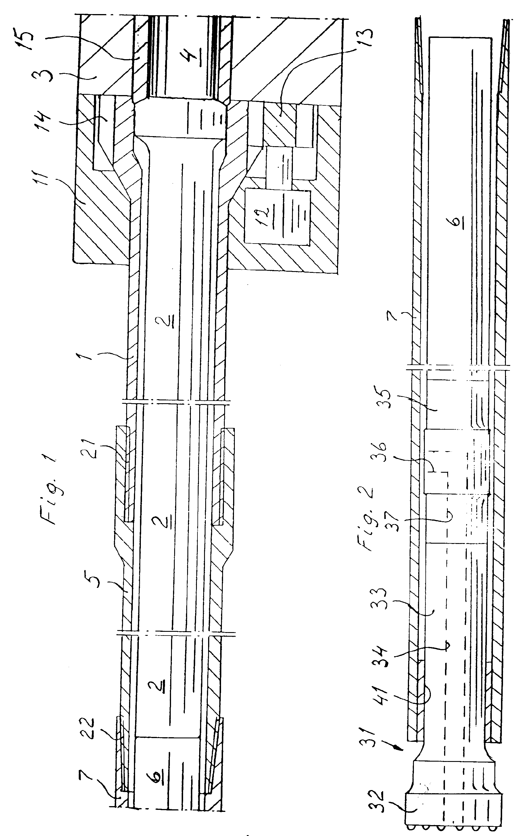
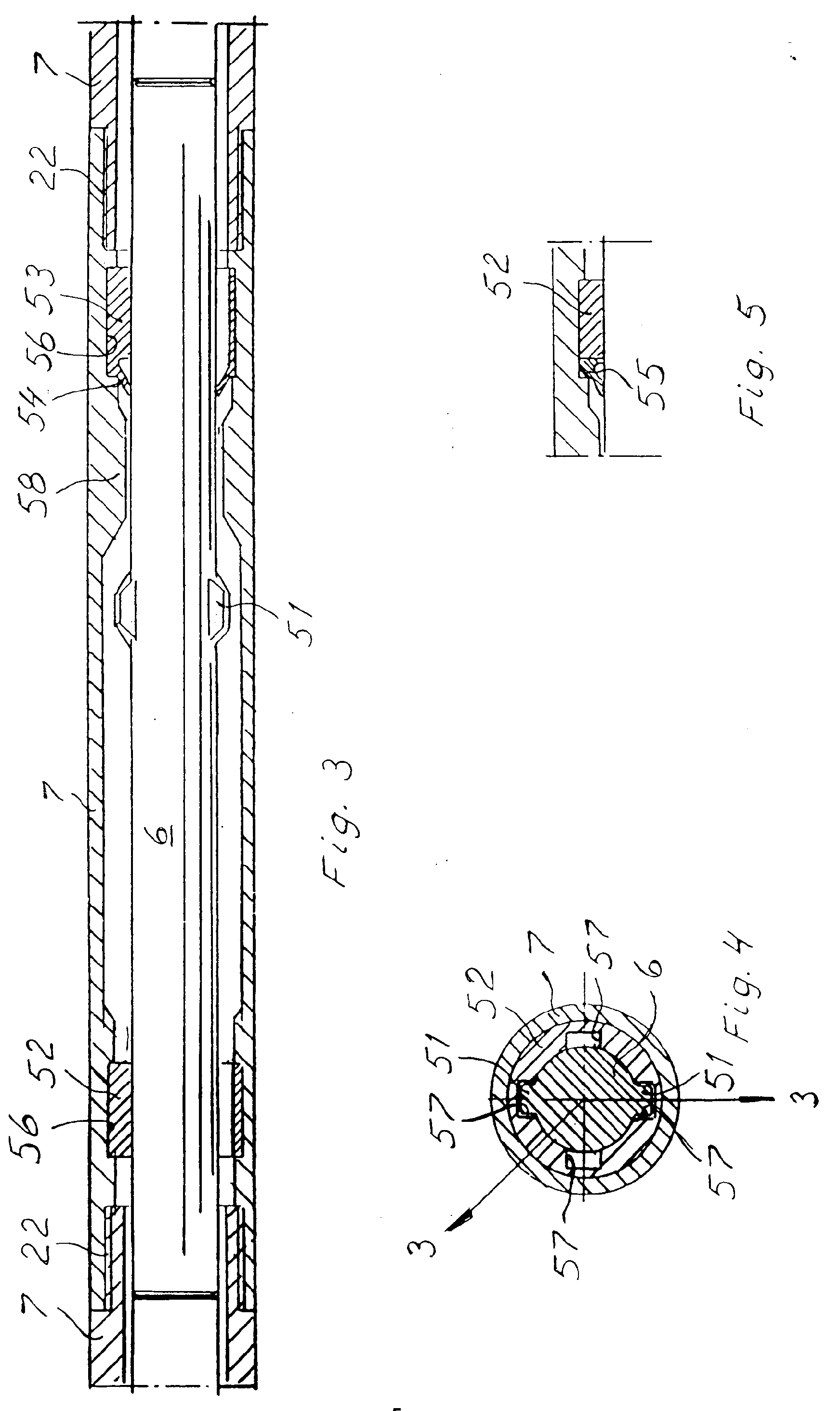
[0005] An embodiment of the invention is described below with reference to the accompanying
drawings where fig 1 schematically shows a section through the rear part of a device
according to the invention. Fig 2 shows a section through the front part of the device
according to fig 1. Fig 3 shows a part of the device more in detail. Fig 4 shows a
section through the device according to fig 3 in a specific phase of the mounting
of a central rod. Fig 5 shows an alternative embodiment of one of the guides.
[0006] The device shown in the drawings comprises a machine housing 3 in which a hammer
piston 4 is movable to-and-fro to impact a drill tool. The hammer piston is guided
in a sleeve 15. The machine housing comprises a front part 11 in which a drill sleeve
1 is rotatably arranged. The drill sleeve is rotated by a rotary device comprising
a rotation motor 12 with a gear 13 which gears with teeth 14 on the drill sleeve.
The drill sleeve 1, which extends out of the machine housing, is at its front end
provided with a thread 21 by means of which the drill sleeve is connectable with a
tube 5 which forms an extension of drill sleeve 1. Tube 5 is by means of a threaded
connection 22 connected with a set of tubes 7. The set of tubes comprises a number
of tubes which are connected with each other by means of threaded connections 22.
A drill bit 31 is by means of a splined coupling 41 connected to the front end of
the set of tubes. A rod 2 is glidably arranged in drill sleeve 1 to transfer the impact
energy of hammer piston 4 to a set of rods 6 which is axially movable in the set of
tubes 7. The set of rods comprises a number of drill rods which rest loosely against
each other. The set of rods transfers the energy of the hammer piston, via a rod 35
arranged adjacent to the drill bit, to the drill bit. Drill bit 31 comprises a work
part 32 and a shaft 33. Drill bit 31 is provided with a flushing channel 34 which
in shaft 33 has axial extension only. Rod 35 arranged adjacent to the drill bit comprises
an axial flow channel 37 connecting to flushing channel 34 in drill bit 31. A channel
36 connects the envelope surface of the rod with flow channel 37. During drilling
flushing medium is supplied in a not shown way to the space between the set of rods
6 and the set of tubes 7. The flushing medium is from there conducted through channel
36, flow channel 37 and flushing channel 34 to the drill area for flushing away drill
cuttings. The rods in the set of rods are provided with projections 51 to prevent
the rods from falling out from the set of tubes. The length of drill bit 31 should
be relatively short in order to be inexpensive to manufacture. Since it should be
well guided by the set of tubes 7 it should not be too short. It has turned out that
the length of the drill bit should be less than 80%, preferably less than 70%, of
the length of the hammer piston. The sum of the length of drill bit 31 and the adjacent
rod 35 should be substantially equal to the length of hammer piston 4. The rods between
rod 35 and hammer piston 4 can be of arbitrary length without prejudice to the transfer
of impact energy from the hammer piston to the drill bit.
[0007] In figs 3 and 4 it is shown how rods 6 are stored in tubes 7. Projections 51 work
together with part 58 on the tubes as axial stop for the rods 6. In practical work
one normally has two tubes with rods in as tool unit. The tubes are then mirror-inverted
relative to each other so that parts 58 are situated at the ends being most distant
from each other. Tubes 7 are provided with grooves 56 in which elastic bushings 52,53
are axially fixed. As is shown in fig 4 the bushings are provided with a number of
grooves 57 through which the projections 51 can be moved. Fig 4 shows a rod and a
bushing when the projections are moved through. Grooves 57 also serve as flushing
medium channels. In the shown example bushing 53 is provided with a lip 54 the purpose
of which is to prevent flushing liquid from passing towards the right in the figure
in connection with the adding of rods at upwards drilling. At upwards drilling of
long holes large amounts of flushing liquid can be present between the set of rods
and the set of tubes.
[0008] Lip 54 is in practice provided with a number of longitudinal cuts so that the lip
easily opens when flushing liquid is pumped forward and easily closes when the flushing
liquid pressure is released. When the drill tool is mounted bushings 52,53 are first
put in place. This is done by squeezing the bushings, which are made of a plastic
material, e.g. polyurethane, and inserting them in tube 7. Then the bushings are allowed
to expand in groove 56. Rod 6 is entered from the left in the figure, whereby the
projections are moved through grooves 57 in bushing 52. Then the rod is entered through
bushing 53. The such mounted tool part is then screwed together with another equally
mounted but mirror-inverted tool part, after which the two rods are axially blocked
in the two tubes screwed together. This unit can now be transported at the work place
without risk that the rods fall out.
[0009] In the alternative embodiment according to fig 5 the lip seal 55 is made as a separate
unit resting against bushing 52.
1. Device in impact machines comprising a machine housing (3,11), a hammer piston (4)
movable to-and-fro in the machine housing and arranged for delivering impacts against
a tool and a rotary devices (12,13) for rotation of the tool, whereby the tool comprises
a central set of rods comprising a number of rods (6), a set of tubes comprising a
number of interconnected tubes (7) surrounding the set of rods and means for supplying
flushing medium under pressure to the space between said set of rods and said set
of tubes, characterized in that said rods (6) are guided by elastic bushings (52,53) arranged in said tubes
(7) and that one (53) of said elastic bushings comprises a lip (54) which is arranged
to sealingly rest against the rod (6) when flushing medium is not supplied and allow
passage of flushing medium when flushing medium is supplied.
2. Device according to claim 1, characterized in that said lip (54) is provided with a number of longitudinal cuts, whereby the
lip easily can be readjusted from resting against the rod (6) to allowing passage
of flushing medium or vice versa.
1. Einrichtung in Schlagmaschinen mit einem Maschinengehäuse (3,11), einem in dem Maschinengehäuse
hin- und herbewegbaren Hammerkolben (4), der dazu eingerichtet ist, Schläge gegen
ein Werkzeug abzugeben, und einer Drehantriebseinrichtung (12,13) zum Drehen des Werkzeugs,
wobei das Werkzeug einen zentralen Satz von Stangen mit einer Anzahl von Stangen (6),
einen Satz von Rohren mit einer Anzahl von untereinander verbundenen Rohren (7) die
den Satz von Stangen umgehen, und Mittel zum Zuführen von Spülmedium unter Druck zu
dem Raum zwischen diesem Satz Stangen und diesem Satz Rohren umfaßt, dadurch gekennzeichnet,
daß die Stangen (6) von in den Rohren (7) angeordneten elastischen Büchsen (52,53)
geführt sind, und daß eine der elastischen Büchsen (53) eine Lippe (54) umfaßt, die
dazu eingerichtet ist, dicht gegen die Stange (6) anzuliegen, wenn kein Spülmedium
zugeführt wird, und den Durchgang von Spülmedium zuzulassen, wenn Spülmedium zugeführt
wird.
2. Vorrichtung nach Anspruch 1, dadurch gekennzeichnet, daß die Lippe (54) mit einer
Anzahl von Längseinschnitten versehen ist, wodurch die Lippe von der Anlage an der
Stange (6) zum Durchlassen von Spülmedium leicht zurückgestellt werden kann oder vice
versa.
1. Dispositif dans des machines à percussion comprenant un carter de machine (3, 11),
un piston de marteau (4) pouvant se déplacer dans un mouvement de va-et-vient à l'intérieur
du carter de machine et destiné à fournir des percussions contre un outil, et un dispositif
rotatif (12, 13) destiné à faire tourner l'outil, de façon que l'outil comprenne un
jeu central de tiges comprenant un certain nombre de tiges (6), un jeu de tubes comprenant
un certain nombre de tubes interconnectés (7) entourant le jeu de tiges, et des moyens
pour fournir un fluide de jaillissement sous pression à l'espace compris entre le
jeu de tiges et le jeu de tubes, caractérisé en ce que les tiges (6) sont guidées
par des coussinets élastiques (52, 53) disposés dans les tubes (7), et en ce que l'un
(53) de ces coussinets élastiques comprend une lèvre (54) disposée pour s'appuyer
de manière étanche contre la tige (6) lorsque le fluide de jaillissement n'est pas
fourni, et pour permettre le passage du fluide de jaillissement lorsque ce fluide
de jaillissement est fourni.
2. Dispositif selon la revendication 1, caractérisé en ce que la lèvre (54) est munie
d'un certain nombre de découpes longitudinales de façon qu'on puisse rerégler facilement
cette lèvre à partir de sa position d'appui contre la tige (6) pour permettre le passage
du fluide de jaillissement, ou vice-versa.